FULL ENJOY 🔝 8264348440 🔝 Call Girls in Diplomatic Enclave | Delhi
Inertia dynamics sfc1000f_specsheet
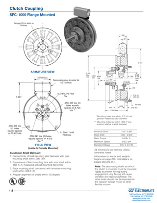
1. Clutch Coupling
SFC-1000 Flange Mounted
Removable plug in ends for
Customer Shall Maintain:
1. Concentricity of field mounting pilot diameter with rotor
mounting shaft within .006 T.I.R.
2. Squareness of field mounting face with rotor shaft within
.006 T.I.R. measured at field mounting bolt circle.
3. Rotor mounting shaft concentric with armature mounting
shaft within .006 T.I.R.
4. Angular alignment of shafts wtihin 1/2 degree.
118
1.546
2.687
* Mounting holes are within .010 of true
position relative to pilot diameter.
** Mounting holes are within .008 of true
position relative to pilot diameter.
Armature Shaft .750 – 2.687
Rotor Shaft .500 – 2.000
Static Torque 240 lb. ft.
Maximum Speed 3,600 rpm
Standard Voltage D.C. 6, 24, 90
See page 252 for details on
Bushings.
ARMATURE VIEW
FIELD VIEW
(Inside & Outside Mounted)
1/2" conduit.
5.378/5.376 Pilot
Dia.
3.750 Max.
7.687
.358/.338 dia. (6)
holes equally
spaced on 6.125
dia. *
.358/.338 dia.
(8) holes
equally spaced
on 10.625 dia.
*
11.500/11.498
.350/.341 dia. (6) holes Pilot Dia.
equally spaced on 4.875
dia. **
.093
2.500
.562 Max.
.570/.554
6.531
.250
.234
.062
.500
1.375
.921
5/16-18
UNC-3A
10.328
Max.
Dia. 6.000
Dia.
4.093
Dia. 1.250
4.128
4.126
Pilot
Dia.
5.359 Max.
® U
L
All dimensions are nominal unless
otherwise noted.
Information on inertia and weights
begins on page 239. Coil data is on
pages 250 and 251.
Note: The two mating shafts on which
the clutch is mounted must be mounted
rigidly to prevent flexing during
engagement. Any flexing will cause
vibration and rapid clutchwear. The
drive motor should not be mounted on
the reducer "scoop" mount or other
flexible mounts.
Sold & Serviced By:
ELECTROMATE
Toll Free Phone (877) SERVO98
Toll Free Fax (877) SERV099
www.electromate.com
sales@electromate.com
2. 1
2
3
4-1
4-2
4-3
4
(Shipped Assembled)
4-4
4-6
4-5
9A
10A
Clutch Coupling
SFC-1000 Flange Mounted
11
9B
8
6 7
5
11
10B
119
Drawing I-25584
Item Description Part Number Qty.
1 Bushing* 1
3/4" to 2-11/16" Bore 180-0026 to 180-0057
2 Retainer Ring 748-0007 1
3 Splined Hub 540-0062 1
4 Armature & Splined Adapter 5202-111-001 1
4-1 Capscrew 797-0341 3
4-2 Splined Adapter 104-0009 1
4-3 Autogap Accessory 5322-101-004 1
4-4 Spacer 748-0333 3
4-5 Armature 5322-111-036 1
4-6 Locknut 661-0004 3
5 Mounting Accessory 5201-101-007 1
6 Rotor 1
Standard Friction Material 5202-751-003
†Optional LK Facing 5202-751-007
7 Bushing* 1
1/2" to 2" Bore 180-0155 to 180-0179
8 Rotor Hub 540-0315 1
9A Field - Inside Mounted 1
6 Volt 5202-451-004
24 Volt 5202-451-006
90 Volt 5202-451-007
Item Description Part Number Qty.
9B Field - Outside Mounted 1
6 Volt 5202-451-011
24 Volt 5202-451-013
90 Volt 5202-451-014
10A Mounting Accessory - I.M. 5321-101-001 1
10B Mounting Accessory - O.M. 5321-101-002 2
11 Conduit Box 5200-101-012 1
How to Order:
1. Specify Bore Size for Item 1.
2. Specify Bore Size for Item 7.
3. Specify Voltage for Item 9A or 9B.
4. Specify Inside Mounted for Items 9A and 10A
or Outside Mounted for Items 9B and 10B.
5. See Controls Section.
Example:
SFC-1000 Clutch Coupling per I-25584 - 90 Volt, Inside
Mounted, 1-1/4" Bore (Item 1), 1-1/2" Bore (Item 7)
These units, when used in conjunction with the correct
Warner Electric conduit box, meet standards of UL508
and are listed under guide card #NMTR, file #59164.
These units are CSA certified under file #LR11543.
*See page 252 for specific part numbers.
Refer to Service Manual P-207.
†Optional LK facing available. For more information, see
page 232.
Sold & Serviced By:
ELECTROMATE
Toll Free Phone (877) SERVO98
Toll Free Fax (877) SERV099
www.electromate.com
sales@electromate.com