2. CCoonnttrroolllleerr
Controller 524
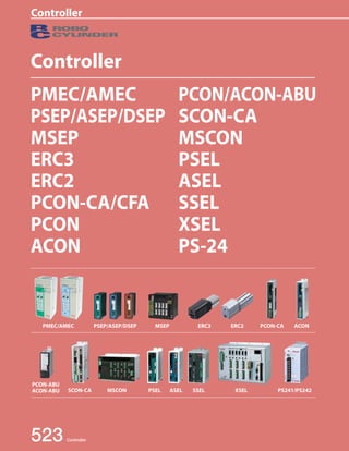
Controller
PMEC
AMEC
PSEP
ASEP
DSEP
MSEP
ERC3
ERC2
PCON
-CA
PCON
ACON
SCON
-CA
MSCON
PSEL
ASEL
SSEL
XSEL
PS-24
Pulse
Motor
Servo
Motor
(24V)
Servo
Motor
(200V)
Linear
Servo
Motor
PMEC 3 Position Controller for RCP3/RCP2 PMEC-C
537 AMEC 3 Position Controller for RCA2/RCA/RCL AMEC-C
PSEP 3 Position Controller for RCP3/RCP2 PSEP-C / CW
ASEP 3 Position Controller for RCA2/RCA/RCL ASEP-C / CW 547
DSEP 3 Position Controller for RCD DSEP-C / CW
Position Controller for RCP4/RCP3/RCP2/RCA2/
RCA/RCL, 8-axis type MSEP-C 563
MSEP
ERC3 ERC3 Controller ERC3 577
ERC2 ERC2 Controller ERC2 597
PCON-CA/CFA Position Controller for RCP4 (with high output
driver) /RCP3/RCP2 PCON-CA / CFA 607
PCON Position Controller for RCP3/RCP2 PCON-CY / PL / PO / SE 623
ACON Position Controller for RCA2/RCA/RCL ACON-C / CG / CY / PL / PO / SE 631
PCON-ABU Simple Absolute Unit for PCON/ACON Controller PCON / ACON-ABU 641 ACON-ABU
SCON-CA Position Controller for RCS3/RCS2 SCON-CA 643
MSCON Position Controller for RCS3/RCS2, 6-axis type MSCON-C 655
PSEL Program Controller for RCP3/RCP2 PSEL-CS 665
ASEL Program Controller for RCA2/RCA/RCL ASEL-CS 675
SSEL Program Controller for RCS3/RCS2 SSEL-CS 685
XSEL Multi-axis Program Controller for RCS3/RCS2 X-SEL-J / K / P / Q / R / S 695
PS-24 24-VDC Power Supply for ROBO Cylinder PS-241 / 242 717
3. Controller
Controller/Actuator Correspondence Table
Classification Positioner Type Controller model PMEC-C AMEC-C PSEP-C
RCP4 ● ●
RCP2/RCP3 ● ● ● ● ● RCP2-HS8 ●
RCA/RCA2 ● ● ● RCA2-SA2A ● ● ●
RCS2/RCS3 Rod type
— — — — — (*5) ● ● — Regenerative resistor unit — — — — — — — — — Supported actuators Data
Varies
( depending on the controller type) Expansion I/Os (PIOs) (Not expandable) DeviceNet 525 Controller
Controller
PMEC
AMEC
PSEP
ASEP
DSEP
MSEP
ERC3
ERC2
PCON
-CA
PCON
ACON
SCON
-CA
MSCON
PSEL
ASEL
SSEL
XSEL
PS-24
Pulse
Motor
Servo
Motor
(24V)
Servo
Motor
(200V)
Linear
Servo
Motor
/W
ASEP-C
/W
DSEP-C
/W MSEP-C PCON-CA PCON-CFA PCON-CY/
PL/PO/SE
Simple Absolute Incremental Incremental
(*1) The “Motor type” field indicates the motor size for a pulse motor (P) and motor wattage for a servo motor.
(*2) RCS2-RA7/SRA7/5N actuators cannot be connected to XSEL-P/Q controllers of 5/6-axis type, XSEL-R/S controllers or MSCON controllers.
Appearance
Input voltage AC100V
AC200V AC100V DC24V Number of controllable axes 1 axis only 1 to 8 axes 1 axis only Motor type (*1)
20P, 20SP,
28P, 28SP,
35P, 42P, 56P
2, 5, 5S,
10, 20,
20S, 30
20P, 20SP,
28P, 28SP,
35P, 42P, 56P
2, 5, 5S,
10, 20,
20S, 30
2.5
20P, 20SP,
28P, 28SP,
35P, 42P, 56P
60P,
86P
20P, 20SP,
28P, 28SP,
35P, 42P, 56P
Slider type
RCP4 ● ●
RCP3 ● ● ● ● ● RCP4-RA8/RA10 ●
RCP2 ● ● ● ● ●
RCA/RCA2 ● ● ● RCA2-RA2A ● ● ●
RCS2 RCS2-5N RCS2-RA13R RCS2-RA13R with Load cell RCD ●
Table type
RCP3 ● ● ● ● ● RCA/RCA2 ● ● ● RCA2-3NA/4NA ● ● ● RCS2 RCS2-5N Gripper type RCP2 ● ● ● ● ● RCS2 Rotary type RCP2 ● (*3) ● (*3) ● ● ● RCS2 Linear Servo type RCL ● ● ● Cleanroom
type
RCP4CR ● ●
RCP2CR ● ● ● ● ● RCP2CR-HS8 ●
RCACR ● ● ● RCS2CR/RCS3CR RCP4W ●
Dustproof/
splash-proof
RCP2W ● ● ● ● ● type
RCAW ● ● ● RCS2W Position detection method Incremental Incremental
Simple Absolute Incremental
Incremental
(Simple absolute unit
can be connected)
Supported absolute batteries — SEP-ABUM
SEP-ABUM-W — MSEP-ABB
AB-7
SEP-ABU
SEP-ABUS
— PCON-ABU Number of programs
No program is required. Number of program steps Number of multi-tasking programs Number of positions Max. 3 points Max. 3 points Max. 512 points Teaching pendant SEP-PT/CON-PTA-C/
CON-PDA-C/CON-PGAS-C-S
CON-PTA-C
CON-PDA-C
CON-PGA-C-S
CON-PTA-C CON-T/TGS
CON-PDA-C
CON-PGAS-C-S
CON-PTA-C
CON-T/TGS
CON-PDA-C
CON-PGA-C-S
PC software MEC PC software
(Free)
RCM-101-MW
RCM-101-USB
Standard I/Os (PIOs) 4 input points/4 output points 4 input points
4 output points
16 input points
16 output points
— — — — — ● ● ● — CC-Link — — — — — ● ● ● — PROFIBUS-DP — — — — — ● ● ● — MECHATROLINK-I/II — — — — — — ● ● — CompoNet — — — — — ● ● ● — Ethernet — — — — — — — — — EtherNet/IP — — — — — ● ● ● — EtherCAT input tool
Supported field net-works
5. Controller PMEC
AMEC
527 Controller
Controller
PSEP
ASEP
DSEP
MSEP
ERC3
ERC2
PCON
-CA
PCON
ACON
SCON
-CA
MSCON
PSEL
ASEL
SSEL
XSEL
PS-24
Pulse
Motor
Servo
Motor
(24V)
Servo
Motor
(200V)
Linear
Servo
Motor
Controller Overview
The ROBO Cylinder model can be selected from an ultra-simple type, which is operable with the
same controls as a solenoid valve, to a high functionality type compatible with networks;
A variety of models are available according to the customer's usage.
Controller types can be categorized according to the 3 groups below based on their operations.
● Operable simply with an ON/OFF signal; easy-to-
operate type.
● Operable with the same signal as a solenoid
valve.
● Pulse train input type is available as well which
is operable freely based on the customer's
control.
● Standalone operation available without
master devices such as a PLC.
● Interpolated motion for 2-6 axes is possible;
available for application and transferring
movements.
● Connection to a main field network such as
DeviceNet, CC-link, or EtherNet/IP is available;
applicable for large scale equipment.
● Position can be specified directly using a numeric
value; there will be no limit of positioning points.
● Only one dedicated cable is needed; The number
of operational steps will be significantly reduced.
ROBO Cylinder
Controllers
Positioner
Type
Program
Type
Network
Type
6. Controller
Controller 528
Controller
PMEC
AMEC
PSEP
ASEP
DSEP
MSEP
ERC3
ERC2
PCON
-CA
PCON
ACON
SCON
-CA
MSCON
PSEL
ASEL
SSEL
XSEL
PS-24
Pulse
Motor
Servo
Motor
(24V)
Servo
Motor
(200V)
Linear
Servo
Motor
See
page 529.
See
page 531.
See
page 533.
3-Position Controller
AC100V/AC200V Type
PMEC/AMEC
3-Position Controller
DC24V Type
PSEP/ASEP/DSEP
Program Controller
DC24V Type
PSEL/ASEL
Network
Controller
DC24V Type
MSEP
Network Compatible Controller
DC24V/AC100V/AC200V Type
PCON/ACON/SCON/PSEL/ASEL/SSEL/XSEL
Network
Dedicated
Controller
DC24V Type
MSCON
Program Controller
AC100V/AC200V Type
SSEL/XSEL
Position Controller
DC24V/AC100V/AC200V Type
PCON/ACON/SCON
7. Controller PMEC
AMEC
Positioner Type
The positioner type controller stores positions to which the actuator is moved by specifying a
target position number.
If you are considering motorizing your air-cylinder system, the positioner type is an ideal
choice because this controller can directly use the signals you have been using to operate
your air cylinder. This means that you can motorize your system with minimum changes to
significantly improve the productivity of your system.
1 No programming needed
The positioner type controller operates by selecting the target position
number externally using I/O after teaching the position data.
Therefore, no operation programming is needed, allowing for immediate
operation directly after mounting to the equipment.
2 Operation using the same signal as solenoid valve possible (PMEC/AMEC, PSEP/ASEP/DSEP controllers)
4 Wide Variations and Functions
529 Controller
Controller
PSEP
ASEP
DSEP
MSEP
ERC3
ERC2
PCON
-CA
PCON
ACON
SCON
-CA
MSCON
PSEL
ASEL
SSEL
XSEL
PS-24
Pulse
Motor
Servo
Motor
(24V)
Servo
Motor
(200V)
Linear
Servo
Motor
Positioner controllers are available in many different types, from the 3-point positioning type
that accepts the same operation signals used for air cylinders, to the enhanced positioning type
accommodating up to 512 points and the space-saving type that can connect up to 8 axes per
controller. Choose the type that best meets your specific application.
Each controller also comes with various functions including smart tuning and maintenance, all
designed to fully demonstrate the performance of your actuator.
Output signals
such as position
complete and
alarm signal
Position number
(select 512 points)
start signal
Position data
PLC
I/O
Same as single solenoid-type valve, traveling between front/back ends is
possible only by the single ON/OFF.
Furthermore, if the double solenoid-type valve signal (two signals) are used,
positioning at 3 points including an intermediate position is possible.
Signal ON
Signal OFF
Move to front end
Move to back end
3 Reasonable price
A reasonable price range is offered for the pulse motor type controllers which
maintain the effective functionality of a servo motor.
The PMEC controller, including the power supply, PC software and communication
cable, is sold as a set at a reasonable price.
8. Controller
Controller 530
Controller
PMEC
AMEC
PSEP
ASEP
DSEP
MSEP
ERC3
ERC2
PCON
-CA
PCON
ACON
SCON
-CA
MSCON
PSEL
ASEL
SSEL
XSEL
PS-24
Pulse
Motor
Servo
Motor
(24V)
Servo
Motor
(200V)
Linear
Servo
Motor
Every element needed for operation such as the controller,
power supply, PC software and communication cable, etc. are
supplied in the set so that direct operation right after the
purchase is possible.
Intuitive operation is possible without the need for instruction.
Acceleration/deceleration and speed can be programmed from
the front panel of the controller.
Operable with the same signals as a solenoid valve.
Power supply of the controller is single-phase AC100V/AC200V
(Only AC100V for AMEC)
Operable with the same signals as a
solenoid valve.
Splash-proof type having good
resistance to water splashes.
Simple absolute type setting which
eliminates the need for home return
upon power-on.
Controller power supply: DC24V
PSEP
Positioning is possible for up to 512 points.
Compatible for pulse train input control. (MSEP is excluded)
When combined with the RCP4, the PCON-CA achieves significantly
higher performance of up to 1.5 times the maximum speed and twice the
payload of an existing model of comparable size.
With the offboard tuning function you can increase the maximum
acceleration/deceleration of the SCON-CA to 2G.
Despite its compact body, the MSEP is able to connect and operate up to
8 actuator axes.
You can choose the absolute specification(*) that makes home return no
longer necessary, for all controllers in the PCON, ACON, SCON and MSEP
series.
(*) PCON, ACON and MSEP series are simple absolute specifications.
PMEC
ASEP DSEP
PCON
ACON
MSEP SCON
AMEC
PMEC/AMEC Controller
PSEP/ASEP Controller
PCON/ACON/SCON/MSEP Controller
See
page 537.
See
page 547.
See
page 607.
See
page 631.
See
page 643.
See
page 563.
9. Controller PMEC
AMEC
Program Type
The program type controller executes programs that are input to it.
Programs input to the controller are used to perform various tasks such as operating the
actuator and communicating with external equipment. Ideal for small systems where a PLC is
not required which leads to cost savings.
1 High-level control available using simple language.
2 Interpolation possible up to 2/8 axes
3 Controlling external equipment is possible
4 No home return needed for absolute type and simple absolute type
531 Controller
Controller
PSEP
ASEP
DSEP
MSEP
ERC3
ERC2
PCON
-CA
PCON
ACON
SCON
-CA
MSCON
PSEL
ASEL
SSEL
XSEL
PS-24
Pulse
Motor
Servo
Motor
(24V)
Servo
Motor
(200V)
Linear
Servo
Motor
A program is generated for the program type controller using the simple
and easy Super SEL Language to execute operation of the actuator and
communication between peripheral equipment.
Expert knowledge is not needed to use the Super SEL Language, so it's
easy to create programs even for beginners.
Simultaneous movement of the actuators is possible up to 2 axes for PSEL/
ASEL/SSEL controllers and 8 axes for the XSEL controller.
Depending on the program, interpolation is available to easily perform arc or
path movements needed for dispensing jobs.
Output
conveyor
stop signal
Input
sensor signal
Multi-purpose I/O signals are available for the controller which makes
communication with peripheral equipment possible.
Therefore, receiving signals from sensors and such through the controller
or outputting signals from the controller to lamps or moving equipment,
etc. to operate them is possible.
A direct operation without home return is possible upon power-on if an absolute type
actuator and controller are applied for ASEL/SSEL/XSEL Controllers.
The PSEL controller is also operable without home return just like an absolute type
actuator by installing the simple absolute unit between the actuator and the controller.
10. Controller
See
page 685.
Controller 532
Controller
PMEC
AMEC
PSEP
ASEP
DSEP
MSEP
ERC3
ERC2
PCON
-CA
PCON
ACON
SCON
-CA
MSCON
PSEL
ASEL
SSEL
XSEL
PS-24
Pulse
Motor
Servo
Motor
(24V)
Servo
Motor
(200V)
Linear
Servo
Motor
Program controller with reasonable price and compact body.
Interpolation of up to 2 axes is possible which is applicable for
dispensing jobs.
By selecting the positioner mode, can be used in the same manner as
the position controller.
Communication via PC USB port and direct USB cable is possible with
integrated USB port.
Can store up to 1500 points for PSEL/ASEL and 20,000 points for SSEL.
Absolute type available for ASEL/SSEL controllers. PSEL controller is
available for the same operation if a simple absolute unit is connected.
Controller power supply is DC24V for PSEL/ASEL and single-phase
AC100V/200V for SSEL.
High-function controller with up to 8 axes that can be
simultaneously controlled.
Precise dispensing jobs are possible through high velocity
uniformity and tracking accuracy.
Absolute type available for selection.
A maximum of 53,332 points can be stored for positioning.
Expansion I/O is available up to a maximum of 576 points.
Up to 16 PCON/ACON/SCON/MSEP controller axes can be
connected via serial communication or field network to operate
ROBO Cylinders using programs stored in the XSEL controller.
PSEL
ASEL
SSEL
XSEL
PSEL/ASEL/SSEL Controller
XSEL Controller
See
page 665.
See
page 675.
See
page 695.
11. Controller PMEC
AMEC
Network Type
The network type controller is available for field networks or serial communication.
Compatible with the majority of main field networks widely used over the world.
There is a large variety available for use with various kinds of FA equipment such as a PLC or
touch panel, etc.
1 Compatible with main field networks
Direct connection is possible with main field networks such as
DeviceNet or CC-Link, etc.
A position controller is available for an operation defined by
movement specified with position number and direct coordinate
value using the network. (When defining coordinate values
directly, there is no restriction for the number of positioning
points.)
533 Controller
Controller
PSEP
ASEP
DSEP
MSEP
ERC3
ERC2
PCON
-CA
PCON
ACON
SCON
-CA
MSCON
PSEL
ASEL
SSEL
XSEL
PS-24
Pulse
Motor
Servo
Motor
(24V)
Servo
Motor
(200V)
Linear
Servo
Motor
Compatible Networks and Functions
Controller series
Positioner Type Program Type
PCON-CA ACON SCON-CA MSEP MSCON PSEL ASEL SSEL XSEL
Appearance
Field
network
types
DeviceNet ● ● ● ● ● ● ● ● ●
CC-Link ● ● ● ● ● ● ● ● ●
PROFIBUS-DP ● ● ● ● ● ● ● ● ●
MECHATROLINK
-I/II ● ● ● — — — — — —
CompoNet ● ● ● ● ● — — — —
Ethernet — — — — — — — — ●
EtherNet/IP ● ● ● ● ● — — — ●
EtherCAT ● ● ● (*2) (*2) — — — ●
Applicable
ROBO Cylinder
RCP4
RCP3
RCP2
RCA2
RCA
RCL
RCS3
RCS2
RCP4
RCP3
RCP2
RCA2
RCA
RCL
RCS3
RCS2
RCP3
RCP2
RCA2
RCA
RCL
RCS3
RCS2
RCS3
RCS2
Maximum number of
positioning points (*1) 768 points 256 points 1,500 points 20,000 points 53,332 points
Operating
method
Movement by
specifying positions
Movement by
specifying direct values X X X X
(*1) When it is operated by movement by specifying direct values, the number of positioning points is unlimited. (*2) To be released soon.
12. Controller
2 Operating Up to 16 ROBO Cylinder Axes from One XSEL Controller
The RC gateway function of the XSEL controller lets you connect multiple ROBO Cylinder controllers via serial
communication or DeviceNet communication to operate up to 16 axes using programs stored in the XSEL controller.
Combined with up to 8 axes that can be operated directly by the XSEL controller, you can effortlessly operate a
maximum of 24 axes from one controller.
Another advantage is that wiring is much easier compared to when ROBO Cylinder controllers are PIO-controlled.
Up to 16 axes can be operated.
Controller 534
Controller
PMEC
AMEC
PSEP
ASEP
DSEP
MSEP
ERC3
ERC2
PCON
-CA
PCON
ACON
SCON
-CA
MSCON
PSEL
ASEL
SSEL
XSEL
PS-24
Pulse
Motor
Servo
Motor
(24V)
Servo
Motor
(200V)
Linear
Servo
Motor
XSEL
P/Q/R/S
PCON
ACON
SCON-CA
MSCON MSEP ERC2
Directly operated by the XSEL controller
Up to 8 axes can be operated.
Specification
(Note) DeviceNet connection only supports IAI controllers.
Serial (RS485) communication or DeviceNet communication
Single-axis/Cartesian robots
Serial Communication Type DeviceNet Communication Type
Supported controllers XSEL-P/Q/R/S type XSEL-P/Q/R/S type (*1)
Connectable controllers
ERC2-SE
PCON-SE/ACON-SE
SCON-CA
ROBONET
PCON-DV/ACON-DV
SCON-DV/MSEP-DV
MSCON-DV
* All controllers must be of the DeviceNet
specification.
Maximum number of connectable
ROBO Cylinder axes 16 16
Baud rate 230.4kbps 500kbps
Communication cable length Total cable length of no more than 100m Total cable length of no more than 100m
Required connection
equipment
RCB-CV-GW
CB-RCB-SIO050
CB-RCB-CTL002
DeviceNet gateway master board (*2)
(*1) XSEL-P/Q controllers of DeviceNet communication type must be custom-ordered. (XSEL-R/S controllers of this type are available as standard models.)
(*2) Your XSEL controller will come with this board if an applicable code is specified in the model name of the controller.
13. Controller PMEC
AMEC
Network Type
3 Vision System
With the XSEL controller, you can directly connect a vision system of any leading brand to take advantage of
the convenience of vision system functions, such as reading coordinate values into the controller and using
these coordinates to move actuators.
(1) Any leading vision system can be connected directly
High-functional vision systems from leading brands, such as Omron, Keyence and Cognex, can be used with ease.
Brand Model Interface
Cognex In-Sight 5000 series Ethernet
Omron F210-C10 FZ3 — RS232C
Keyence CV2000 CV3000 CV5000 XG-7000
535 Controller
Controller
PSEP
ASEP
DSEP
MSEP
ERC3
ERC2
PCON
-CA
PCON
ACON
SCON
-CA
MSCON
PSEL
ASEL
SSEL
XSEL
PS-24
Pulse
Motor
Servo
Motor
(24V)
Servo
Motor
(200V)
Linear
Servo
Motor
Examples of vision system models
Coordinate
values
Camera
controller
Controller
Position data
XSEL
R/S
PLC
CC-Link
I/Os communications
Ethernet
Vision system data
Omron
Keyence
Cognex
(2) No need for complex communication programs
Ethernet
RS232C
Coordinates read by the camera are sent to the robot controller via a dedicated command and stored as part of
position data in the controller. There is no need for complex communication programs, etc.
(3) Able to communicate with other networks while communicating with the vision system via Ethernet
XSEL-R/S controllers can communicate with DeviceNet, CC-Link or PROFIBUS-DP while communicating with the
vision system via EtherNet/IP or EtherCAT.
This means that, for example, you can use Ethernet for communication between the XSEL controller and vision
system, while allowing the XSEL controller to send and receive I/Os to/from peripherals via a CC-Link network.
* XSEL-P/Q controllers can be set up to support one network selected from the types mentioned above.
14. Controller
See page
563.
See page
655.
Controller 536
Controller
PMEC
AMEC
PSEP
ASEP
DSEP
MSEP
ERC3
ERC2
PCON
-CA
PCON
ACON
SCON
-CA
MSCON
PSEL
ASEL
SSEL
XSEL
PS-24
Pulse
Motor
Servo
Motor
(24V)
Servo
Motor
(200V)
Linear
Servo
Motor
SCON
SSEL
MSEP Controller
■ Up to 8 axes of pulse/servo motor actuators can be connected
to this compact controller of just 123mm (W) x 115mm (H) in size.
The compact body, which is 60% slimmer than a comparable
model, saves space in the control panel.
■ You can specify the target position numerically.
■ Significantly shorter communication time within the controller.
(Supported actuators) RCP4/RCP3/RCP2/RCA2/RCA/RCL series
■ Dedicated low-cost network controller of space-saving design
that connects up to 6 axes.
■ You can specify the target position numerically.
■ Significantly shorter communication time within the controller.
(Supported actuators) RCS3/RCS2 series.
PCON ACON
XSEL
PSEL ASEL
MSEP
MSCON
See page
643.
See page
631.
See page
607.
See page
658.
See page
675.
See page
665.
See page
695.
MSCON Controller
Controller compatible with field network *Network type set for each controller
■ Able to connect to major networks directly.
■ The position controllers let you operate your actuator by directly
sending the values of target position, speed, acceleration, etc.,
via network.
15. PMEC/AMEC Controller
ROBO Cylinder 3-position controller MEC (Mechanical Engineer Control)
Feature
537 PMEC / AMEC
Controller
PMEC
AMEC
PSEP
ASEP
DSEP
MSEP
ERC3
ERC2
PCON
-CA
PCON
ACON
SCON
-CA
MSCON
PSEL
ASEL
SSEL
XSEL
PS-24
Pulse
Motor
Servo
Motor
(24V)
Servo
Motor
(200V)
Linear
Servo
Motor
Controller
Power supply
PC connection cable
3-position, AC100/200V controller
for RCP2/RCP3 Series
1Manual setting
2 Adjustment
3Trial operation
PLC
Air cylinder Replacement ROBO cylinder
3-position, AC100V controller
for RCA/RCA2/RCL Series
1 Low Cost
The MEC package, which combines a controller, power supply,
acceleration/speed change function and PC connection cable, among
others, is at an affordable price. The MEC PC software can be
downloaded free of charge from IAI’s website.
2 Easy Operation
Even a beginner can set up the controller without reading the
operation manual.
The acceleration and speed can be adjusted using the knobs on
the controller.
* The setting range for acceleration/speed varies depending on the actuator.
Please refer to the instruction manual for further detail.
3 Easy Replacement from your Air-cylinder System
Operation signals are exactly the same as those used to operate air cylinders.
This means that you can use the program of your current PLC directly.
4 Push-motion Operation/Intermediate Stopping
Push-motion operation can be performed in the same manner as you
would with any air-cylinder system.
Also, you can cause the actuator to stop at any desired intermediate point
between the home position and stroke end by changing the setting of the
intermediate point using the MEC PC software.
16. PMEC/AMEC Controller
PMEC C I 2 ENG
Series Type Motor type Encoder type I/O type I/O cable length Power supply voltage Display panel
AMEC C I 2 1 ENG
Series Type Motor type Encoder type I/O type I/O cable length Power supply voltage Display panel
PMEC / AMEC 538
Controller
PMEC
AMEC
PSEP
ASEP
DSEP
MSEP
ERC3
ERC2
PCON
-CA
PCON
ACON
SCON
-CA
MSCON
PSEL
ASEL
SSEL
XSEL
PS-24
Pulse
Motor
Servo
Motor
(24V)
Servo
Motor
(200V)
Linear
Servo
Motor
Model List
Model
Series PMEC AMEC
External View
Applicable actuators RCP2 / RCP3 RCA / RCA2 / RCL
Power supply voltage 100V 100V-240V 100V
Accessories
AC power supply cable (2m)
USB cable (3m)
I/O cable (2m)
I/O connector
EMG connector
Standard mounting bracket
C Standard I Incremental
2 2m
NP NPN type
PN PNP type
1 Single phase AC100V
2 Single phase
AC100~240V
20P For 20 pulse motor
20SP For 20 pulse motor
(dedicated for RCP3-RA2 )
28P For 28 pulse motor
28SP For 28 pulse motor
(dedicated for RA3C)
35P For 35 pulse motor
42P For 42 pulse motor
56P For 56 pulse motor
C Standard I Incremental
2 2m
NP NPN type
PN PNP type
1 Single phase AC100V
2 For 2W motor
5 For 5W motor
5S For 5W motor
(dedicated for RCA2-SA2A)
10 For 10W motor
20 For 20W motor
20S For 20W motor (dedicated for
RCA2-SA4/TA5/RCA-RA3)
30 For 30W motor
17. PMEC/AMEC Controller
PC software
Option
Supplied with the controller
539 PMEC / AMEC
Controller
PMEC
AMEC
PSEP
ASEP
DSEP
MSEP
ERC3
ERC2
PCON
-CA
PCON
ACON
SCON
-CA
MSCON
PSEL
ASEL
SSEL
XSEL
PS-24
Pulse
Motor
Servo
Motor
(24V)
Servo
Motor
(200V)
Linear
Servo
Motor
PLC
PIO Unit
Emergency stop switch
I/O cable (2m)
I/O connector
(At the time of shipment, the EMG connector is short-circuited.)
Supplied with the controller
See page P546 for
maintenance cables.
download
Teaching Pendant for
ROBO Cylinder
(See P543)
<Model CON-PTA-C>
<Model CON-PDA-C>
<Model CON-PGAS-C-S>
Motor-Encoder Integrated Cable
Supplied with the actuator
USB cable (3m) Power cable (2m)
Supplied with the controller
Supplied with the controller
Actuator
PMEC
See page P545 for
maintenance cables.
AMEC
System Configuration
PMEC Single-phase AC100V or
Single-phase AC100~240V
AMEC Single-phase AC100V
I/O Signal Table
MEC PC software
Compatible Controllers
Actuator Controllers
RCP2 series
RCP3 series PMEC series
RCA series
RCA2 series
RCL series
AMEC series
Motion Pattern 2-Position Travel 3-Position Travel
Pin No. Wire Color Signal Type Signal Name Signal Name
1 Brown
PIO power
24V (Note) 24V (Note)
2 Red 0V (Note) 0V (Note)
3 Orange
Input
ST0 (Solenoid A: ON moves to end position, OFF moves to home position) ST0 (Solenoid A: Move signal 1)
4 Yellow — ST1 (Solenoid B: Move signal 2)
5 Green RES (Alarm reset) RES (Alarm reset)
6 Blue — —
7 Purple
Output
LS0 (home position detection)/PE0 (home positioning complete)*1 LS0 (home position detection)/PE0 (home positioning complete)*1
8 Gray LS1 (end position detection)/PE1 (end positioning complete)*1 LS1 (end position detection)/PE1 (end positioning complete)*1
9 White HEND (Homing complete) LS2 (intermediate point detection)/PE2 (intermediate positioning complete)*1
10 Black *ALM (alarm)*2 *ALM (alarm)*2
*1: Signals PE0 through PE2 will be output if the pushing motion was enabled in the initial setting. Otherwise, LS0 through LS2 will be output.
*2: * ALM is ON when normal, and OFF when it is activated.
By using the MEC PC software you can change the stop position data or run a test operation.
In addition, you can change the setting on the intermediate stop function, pushing function or change the coordinates.
The MEC PC software can be downloaded from the IAI website.
IAI Website: www.intelligentactuator.com
(Note) External power supply is needed.
* When using I/O,
external 24V supply
is required.
18. PMEC/AMEC Controller
This motion pattern is between two positions, the home position and the end position. The home and end positions can be configured
numerically (using the MEC PC software or the optional touch panel teaching pendant).
Two motions are possible: A positioning motion moves the rod or the slider to the specified position, and a pushing motion presses the
rod against a workpiece.
Input Signal End Position Data
Position 30mm
Speed 50mm/s
Pushing Force —
Width —
Input Signal Home Position Data
PIO Pattern (2-position travel)
This motion pattern is between two positions, the home position and the end position, which enables a pushing motion
of the rod against a workpiece.
Input Signal End Position Data Push
This motion pattern enables moves between three positions: the end position and the home position, as well as an
intermediate position.
The positions are switched by combining two signals, ST0 and ST1.
PMEC / AMEC 540
Controller
PMEC
AMEC
PSEP
ASEP
DSEP
MSEP
ERC3
ERC2
PCON
-CA
PCON
ACON
SCON
-CA
MSCON
PSEL
ASEL
SSEL
XSEL
PS-24
Pulse
Motor
Servo
Motor
(24V)
Servo
Motor
(200V)
Linear
Servo
Motor
Explanation of PIO Patterns
ST0 Solenoid A ON
Position 0mm
Speed 20mm/s
Pushing Force —
Width —
ST0 Solenoid A OFF
Positioning
When ST0 is turned ON, the slider/rod
moves at 50mm/s to the end position (30mm position).
When ST0 is turned OFF, the slider/rod returns
to the home position (0mm position) at 20mm/s.
PIO Pattern (2-position travel)
(End position)
Speed 50mm/s
(30mm)
(Home Position)
Speed 20mm/s
(0mm)
ST0 Solenoid A ON Position 30mm
Speed 80mm/s
Pushing Force 50%
Width 10mm
When ST0 is turned ON, the actuator moves
the rod to the 20mm position at 80mm/s, and from
there, pushes it at slower speed to the 30mm position.
(End position)
(20mm) (30mm)
* The pushing motion is performed when there is a numerical value in the controller's push force data. (If there is no numerical value, a positioning motion is performed instead.)
Input Signal
ST0 Solenoid A ON
ST1 Solenoid B OFF
Input Signal
ST0 Solenoid A ON*
ST1 Solenoid B ON*
Input Signal
ST0 Solenoid A OFF
ST1 Solenoid B ON
Positioning
When only ST0 is turned ON, the actuator
moves to the starting position at a set acceleration and speed.
When both ST0 and ST1 are turned ON, it will move to the
intermediate position at the set acceleration and speed.
When both are turned OFF, it stops at the current position.
When only ST1 is turned ON, the actuator
moves to the end position at a set acceleration and speed.
* You can also configure the initial settings so
that the rod will move to the intermediate
position with both signals turned OFF, and
stop at the current position with both signals
turned ON.
PIO Pattern (3-position travel)
(Home position)
(0mm)
(Intermediate position)
(10mm)
(End position)
(30mm)
19. PMEC/AMEC Controller
Item Type
Controller Type PMEC AMEC
Connectible Actuators RCP2/RCP3 Series Actuators RCA/RCA2/RCL Series Actuators
Number of Controllable Axes Single axis
Operation Method Positioner Type
Number of Positions 2 positions / 3 positions
Backup Memory EEPROM
I/O Connector 10-pin terminal block
I/O Points 4 input points / 4 output points
Power for I/O Externally supplied DC24V±10%
Serial Communication RS485: 1ch/USB: 1ch
Position Detection Method Incremental encoder
Power Supply Voltage AC100~115V±10% AC100V-240V±10% AC100V~115V±10%
Rated Current 1.3A 0.67A (AC100V)/0.36A (AC200V) 2.4A
Rush Current 30A 15A (AC100V)/30A (AC200V) 15A
Leak Current 0.50mA max 0.40mA max (AC100V)
541 PMEC / AMEC
Controller
PMEC
AMEC
PSEP
ASEP
DSEP
MSEP
ERC3
ERC2
PCON
-CA
PCON
ACON
SCON
-CA
MSCON
PSEL
ASEL
SSEL
XSEL
PS-24
Pulse
Motor
Servo
Motor
(24V)
Servo
Motor
(200V)
Linear
Servo
Motor
Power
Green :Normal
Red: Alarm
Complete
HOME
SAVE
Test run
Manual
Manual
Continuous
Auto
Ext. Start
Accel & Speed Setting
FWD
POS
BACK
POS
Middle
Accel Speed
FWD BACK
RUN STOP
Normal Release
Brake
Teaching Port
226
216
85 2-ø5 through
200
42.5
89.8
82
2
87.8
80
9 182 9
Power
Green :Normal
Red: Alarm
Complete
HOME
SAVE
Test run
Manual
Manual
Continuous
Auto
Ext. Start
Accel & Speed Setting
FWD
POS
BACK
POS
Middle
Accel Speed
FWD BACK
RUN STOP
Normal Release
Brake
Teaching Port
85
4.1 200
8.5 68 8.5
4-M3 tapped hole
[With standard mounting bracket]
The standard mounting bracket is supplied with the controller.
Specifications Table
Outer Dimensions
0.75mA max (AC200V) 0.50mA max
Dielectric Strength Voltage DC500V 1MΩ
Vibration Resistance XYZ directions 10~57Hz One-side amplitude 0.035mm (continuous), 0.075mm (intermittent)
57~150Hz 4.9m/s2 (continuous), 9.8m/s2 (intermittent)
Ambient Operating Temperature 0~40C
Ambient Operating Humidity 10~85% RH (non-condensing)
Ambient Operating Atmosphere Free from corrosive gases
Protection Class IP20
Weight 500g 508g 614g
Note: The minimum/maximum speeds vary depending on the actuator model.
For more information, see the instruction manual, or contact IAI.
20. PMEC/AMEC Controller
Release Used to release the brake of the actuator
Normal The controller automatically controls the brake of the actuator
Indicates the servo status.
On = Servo ON, Off=Servo OFF (Energy-saving) status
Flashing (1Hz)=Auto servo OFF
The LED illuminates if an alarm is turned ON or if the
controller has come to an emergency stop.
Test Operation
Names of movements
PMEC / AMEC 542
Controller
PMEC
AMEC
PSEP
ASEP
DSEP
MSEP
ERC3
ERC2
PCON
-CA
PCON
ACON
SCON
-CA
MSCON
PSEL
ASEL
SSEL
XSEL
PS-24
Pulse
Motor
Servo
Motor
(24V)
Servo
Motor
(200V)
Linear
Servo
Motor
1
2
3
4
5
6
7
8
9
10
PIO connector.......... Connects with a PLC or other external controllers to
communicate inputs and outputs (I/O).
Power LED.................When the power is ON, it illuminates in green.
Control panel........... See below
Brake switch
USB connector.........When using MEC PC software, connect to the computer via USB.
AC inlet....................... Insert the power supply cable.
EMG connector........ Connect the emergency stop button. Short-circuit it if you will not
be using an emergency stop button.
M/PG connector...... Insert the motor/encoder cable that connects with the actuator.
Status LED
RUN
(Green)
ALM (Red)
EMG (Red)
SIO Connector......... Connects with the teaching pendant (CON-PTA, SEP-PT).
Names of Parts and Functions
Power
Green :Normal
Red: Alarm
Complete
HOME
SAVE
Test run
Manual
Manual
Continuous
Auto
Ext. Start
Accel & Speed Setting
FWD
POS
BACK
POS
Middle
Accel Speed
FWD BACK
RUN STOP
Normal Release
Brake
Teaching Port
Manual button
Power
Green :Normal
Red: Alarm
Complete
HOME
SAVE
Test run
Manual
Manual
Continuous
Auto
Ext. Start
Accel & Speed Setting
FWD
POS
BACK
POS
Middle
Accel Speed
FWD BACK
RUN STOP
Normal Release
Brake
Teaching Port
AUTO button
Press this button when operating from
the MEC PC software or the PLC
commands. (Press for at least 1 second)
Explanation of the Control Panel
HOME button
When starting, homing is performed
rst to conrm the 0mm coordinate.
Acceleration/Speed Settings
Congure the actuator's motion.
Explanation of Terms
FWD
POS
BACK
POS buttons
Switch the motion you want to congure
(see types below).
FWD POS: Motion toward the end position
BACK POS: Motion toward the home position
Middle: Motion toward the middle position
(Enabled from the MEC PC software and
switched on by simultaneously pressing FWD
POS and BACK POS buttons to switch.
During a 2-position stop, simultaneous pressing
is disabled.)
SAVE button
Saves the speed and acceleration
adjusted above.
Conrm the saved motion by physically
running the actuator.
FWD button
In a 2-position travel, the actuator moves
from the BACK position to the FWD position.
In a 3-position travel, the actuator moves
from the BACK position to the middle
position, then to the FWD position.
BACK button
The actuator returns to the home position.
RUN button
In a 2-position travel, the actuator moves
back and forth between the FWD and BACK
positions. In a 3-position travel, the actuator
repeats its movement from the BACK
position, middle position, FWD position,
then BACK position.
STOP button
Stops the above operation.
Press this button to set the acceleration
and/or speed, or to run a test operation.
(Press for at least 1 second)
FWD POS BACK POS
Middle
(Middle position)
FWD BACK
Actual movement
(End position)
Middle (Home position)
Acceleration Speed knobs
By turning the knob, you can change the
speed between 1%~100% of the actuator's
maximum speed or rated acceleration /
deceleration.
* The minimum speed may be less than 1% in some cases.
21. PMEC/AMEC Controller
Touch-panel Teaching Pendant for Position Controller
CON-PTA/PDA/PGAS
Adopting an easy-to-use interactive touch-panel menu screen, these simple data devices can be
operated without consulting to the manuals.
1. Color screen for greater ease of view
2. Supporting the takt time minimization function and maintenance information checking/input functions.
3. Position, parameters and other data can be saved in a SD card
4. Built-in clock function records the date time of each event; data can then be saved in a SD card.
Model Numbers/Specifications
Item Description
Options
Model number CON-PTA-C-ENG CON-PDA-C-ENG CON-PGAS-C-S-ENG (set)
Type Standard type Enable switch type Safety-category compliant type
Connectable controllers ACON/PCON/SCON/RACON/RPCON/MSCON/ASEP/PSEP/MSEP/DSEP/AMEC/PMEC /ERC2 (*1) /ERC3
3-position enable switch
Functions
Display 65,536 colors (16-bit colors), white LED backlight
Ambient operating temperature/humidity 0 to 40C, 85% RH or less (Non-condensing)
Environmental resistance IP40 or equivalent
Mass Approx. 570g Approx. 600g
Cable length 5m
Accessories Stylus Stylus
Standard price — — —
543 PMEC / AMEC
Controller
PMEC
AMEC
PSEP
ASEP
DSEP
MSEP
ERC3
ERC2
PCON
-CA
PCON
ACON
SCON
-CA
MSCON
PSEL
ASEL
SSEL
XSEL
PS-24
Pulse
Motor
Servo
Motor
(24V)
Servo
Motor
(200V)
Linear
Servo
Motor
• Position data input/editing
• Moving function (moving to set positions, jogging/inching)
• Parameter editing
• Monitoring (current position, current speed, I/O signals, alarm code, alarm generation time)
• Saving/reading data to/from external SD cards (position data parameters, alarm list)
• Takt time minimization function
• Maintenance information (total number of movements, total distance travelled, etc.)
Stylus, TP adapter (Model number: RCB-LB-TGS)
Dummy plug (Model number: DP-4S)
Controller cable (Model number: CB-CON-LB005)
*1 Among the ERC2 series, only the actuators bearing 4904 or greater number stamped on the serial number label can be connected.
Name of Each Part
■ Name of Each Part/External Dimensions Stylus
Wall-mounting
hook
Enable switch
14 24
10 4
98
Emergency stop button
132
Operation
screen
92.1
5m 180
(50)
■ Option
• Strap (Model number: STR-1)
22. PMEC/AMEC Controller
PMEC / AMEC 544
Controller
PMEC
AMEC
PSEP
ASEP
DSEP
MSEP
ERC3
ERC2
PCON
-CA
PCON
ACON
SCON
-CA
MSCON
PSEL
ASEL
SSEL
XSEL
PS-24
Pulse
Motor
Servo
Motor
(24V)
Servo
Motor
(200V)
Linear
Servo
Motor
● DIN Rail Mounting Bracket MEC-AT-D
■ Dimensions
85
100 100
200
16
103.8
96
PowerGreen :Normal
Red: Alarm
Complete
HOME
SAVE
Test run
Manual
Manual
Continuous
Auto
Ext. Start
Accel Speed Setting
FWD
POS
BACK
POS
Middle
Accel Speed
FWD BACK
RUN STOP
Normal Release
Brake
Teaching Port
● Maintenance cable
■ List of maintenance cable models
Type Cable length Cable length Model Standard price
Integrated
motor-encoder
cable
PMEC RCP3
RCP2-GRSS/GRLS/
GRST/
SRA4R/SRGS4R/
SRGD4R
AMEC RCA2/RCL
1m CB-APSEP-MPA010 —
3m CB-APSEP-MPA030 —
5m CB-APSEP-MPA050 —
PMEC RCP2
1m CB-PSEP-MPA010 —
3m CB-PSEP-MPA030 —
5m CB-PSEP-MPA050 —
PMEC RCP2-RTBS/RTBSL
-RTCS/RTCSL
1m CB-RPSEP-MPA010 —
3m CB-RPSEP-MPA030 —
5m CB-RPSEP-MPA050 —
AMEC RCA
1m CB-ASEP-MPA010 —
3m CB-ASEP-MPA030 —
5m CB-ASEP-MPA050 —
I/O cable
2m CB-APMEC-PIO020-NC —
3m CB-APMEC-PIO030-NC —
5m CB-APMEC-PIO050-NC —
USB cable 3m CB-SEL-USB030 —
23. PMEC/AMEC Controller
[RCP3/RCA2/RCL]-[PMEC/AMEC] Integrated motor-encoder robot cable for indirect connection/ Integrated motor-encoder cable
L
(18) (10)
Actuator side
(45)
[PCON](ACON)
White [ - ](A+)
Black (label)[BK+](LS+)
[RCP2/RCP2CR/RCP2W]-[PMEC] Integrated motor-encoder robot cable for indirect connection
(15)
[RCA/RCACR/RCAW]-[AMEC] Integrated motor-encoder robot cable for indirect connection
(10)
545 PMEC / AMEC
Controller
PMEC
AMEC
PSEP
ASEP
DSEP
MSEP
ERC3
ERC2
PCON
-CA
PCON
ACON
SCON
-CA
MSCON
PSEL
ASEL
SSEL
XSEL
PS-24
Pulse
Motor
Servo
Motor
(24V)
Servo
Motor
(200V)
Linear
Servo
Motor
Components for maintenance
Please refer to the models listed below when arrangements such as cable replacement are needed after purchasing the product.
Model CB-PSEP-MPA
L
(Front view)
(ø8.5)
(15)
(14)
(25)
(26)
(20)
(10)
(14)
Actuator side Controller side
Actuator side Controller side
Black [ ØA ]
Pin number
124536
16
17
56
13
14
1234
10
11
9
12
15
78
18
White [ VMM ]
Red [ ØB ]
Green [ VMM ]
Brown [ Ø/A ]
Yellow [ Ø/B ]
Orange [ BK+ ]
Gray [ BK- ]
NC
NC
Black [ LS+ ]
Brown [ LS- ]
White [ A+ ]
Yellow [ A- ]
Red [ B+ ]
Green [ B- ]
White (label)[VCC]
Yellow (label)[VPS]
Red (label)[GND]
Green (label)[(Spare)]
NC
NC
NC
Shield [ FG ]
Pin number
1234569
10
11
12
78
13
14
15
16
17
18
19
20
21
22
23
24
1st
Connector
2nd
Connector
* c c c indicated the cable length (L)
Lengths up to 20m can be specified Example) 080=8m
*Refer to page A-59 for connectable actuators.
* Robot cable is the standard specification.
Minimum bend radius r = 68mm or larger (when movable unit is used)
Model CB-ASEP-MPA
1st
Connector
2nd
Connector
Actuator side Controller side
Pin number Pin number
Red [ U ] 12——
— 3
18
17
7
16
1234
10
11
14
13
15
658
12
9
Yellow [ V ]
NC
NC
Black [ W ]
NC
Orange [ BK+ ]
Gray [ BK- ]
Black [ LS+ ]
Brown [ LS- ]
White [ A+ ]
Yellow [ A- ]
Red [ B+ ]
Green [ B- ]
Black (label)[Z+]
Brown (label)[Z-]
White (label)[VCC]
Yellow (label)[VPS]
Red (label)[GND]
Green (label)[(Spare)]
NC
NC
NC
Shield [ FG ]
123456789
10
11
12
13
14
15
16
17
18
19
20
21
22
23
24
Actuator side Controller side
(Front view)
(ø8.5)
(20) L
(15)
(10)
(14)
(14)
(25)
(26)
* c c c indicated the cable length (L)
Lengths up to 20m can be specified Example) 080=8m
*Refer to page A-59 for connectable actuators.
* Robot cable is the standard specification.
Minimum bend radius r = 68mm or larger (when movable unit is used)
(30)
(26)
(ø8.5)
(Front view)
NC
Actuator side
Pin number
A1
B1
A2
B2
A3
B3
A4
B4
A6
B6
A7
B7
A8
B8
A5
B5
A9
B9
A10
B10
A11
B11
Controller side
Pin number
12534678
11
12
13
14
15
16
9
10
20
18
17
19
21
24
22
23
Black [ øA ](U)
White [VMM](V)
Brown [ ø/A ](W)
Green [ øB ]( - )
Yellow [VMM]( - )
Red [ ø/B ]( - )
Orange [LS+](BK+)
Gray [LS-](BK-)
Yellow [ - ](A-)
Red [ A+ ](B+)
Green [ A- ](B-)
Black [ B+ ](Z+)
Brown [ B- ](Z-)
Brown (label)[BK-](LS-)
Green (label)[GNDLS](GNDLS)
Red (label)[VPS](VPS)
White (label)[VCC](VCC)
Yellow (label)[GND](GND)
Shield [FG](FG)
NC
NC
Controller side
* c c c indicated the cable length (L)
Lengths up to 20m can be specified Example) 080=8m
Model CB-APSEP-MPA /CB-APSEP-MPA -LC
*Refer to page A-59 for connectable actuators.
Minimum bend radius r = 68mm or larger (when movable unit is used)
24. PMEC/AMEC Controller
[RCP2-RTBS/RTBSL/RTCS/RTCSL]-[PMEC] Integrated motor-encoder robot cable for indirect connection
c c c Model CB-RPSEP-MPA * Robot cable is the standard specification. * indicated the cable length (L)
Lengths up to 20m can be specified Example) 080=8m
Actuator side Controller side
Model CB-APMEC-PIO -NC 050=5m
PMEC / AMEC 546
Controller
PMEC
AMEC
PSEP
ASEP
DSEP
MSEP
ERC3
ERC2
PCON
-CA
PCON
ACON
SCON
-CA
MSCON
PSEL
ASEL
SSEL
XSEL
PS-24
Pulse
Motor
Servo
Motor
(24V)
Servo
Motor
(200V)
Linear
Servo
Motor
Black [ øA ]
Pin number
A1
B1
A2
B2
A3
B3
A6
B6
A7
B7
A8
B8
A4
B4
A5
B5
A9
B9
A10
B10
A11
B11
White [ VMM ]
Brown [ ø/A ]
Green [ øB ]
Yellow [ VMM ]
Red [ ø/B ]
Orange [ LS+ ]
Gray [ LS- ]
Red [ A+ ]
Green [ A- ]
Black [ B+ ]
Brown [ B- ]
NC
NC
Black (label)[BK+]
Brown (label)[BK-]
Green (label)[GNDLS]
Red (label)[VPS]
White (label)[VCC]
Yellow (label)[GND]
NC
Shield [ FG ](FG)
NC
NC
Pin number
12534678
13
14
15
16
789
10
20
18
17
19
21
24
22
23
Actuator side Controller side
(Front view)
(ø8.5)
L
(18) (10)
(45)
(30)
(26)
Minimum bend radius r = 68mm or larger (when movable unit is used)
L
Flat cable (10 pin)
* The 3 types differ in cable length: 020=2m, 030=3m,
I/O cable for PMEC-C/AMEC-C
Pin NO. Electric wire
color Signal
1 Brown PIO Power
2 Red supply
3 Orange
Input
4 Yellow
5 Green
6 Blue
7 Purple
Output
8 Gray
9 White
10 Black
25. PSEP/ASEP/DSEP Controller
(Note 1) When the actuator is connected to the simple
absolute type controller, the model is
considered an incremental model.
(Note 2) It can not be used for the linear servo type.
(Note 3) Not applicable for the DSEP.
547 PSEP / ASEP / DSEP
Controller
PMEC
AMEC
PSEP
ASEP
DSEP
MSEP
ERC3
ERC2
PCON
-CA
PCON
ACON
SCON
-CA
MSCON
PSEL
ASEL
SSEL
XSEL
PS-24
Pulse
Motor
Servo
Motor
(24V)
Servo
Motor
(200V)
Linear
Servo
Motor
Model C/CW
3-position controller
for RCA2/RCA/RCL
When mounting the absolute battery unit,
mount it below the SEP controller to
prevent heat damage.
Signal ON
Signal OFF
Extended
Retracted
SEP controller
Absolute battery unit
Push force can be adjusted from
20 to 70% of the maximum push force.
Model C/CW
3-position controller
for RCP3/RCP2
Model C/CW
3-position controller
for RCD
Feature
1 Can operate with the same signal as a solenoid valve.
The signal that operates the actuator is the same as the signal that operates the air cylinder.
Therefore, the PLC program currently in use can be used without modification even if the air
cylinder is replaced by an electric-powered cylinder.
Either a single solenoid or a double solenoid may be used.
2 Establishes a dustproof type that supports IP53.
We provide dustproof type controllers with an IP53 equivalent (*1) protection structure, so
that the controller can be mounted outside the control panel.
(*1) The bottom surface is excluded.
3 Provides the simple absolute type that can be operated
immediately upon power-ON without homing.
Since the simple absolute type can store the current position with the assistance of the
absolute battery unit during power-up or after the emergency stop is deactivated; it can start
the next operation at that position.
4 Pushing and intermediate stop operation is available.
Like air cylinders, the pushing operation is available. In this operation, you can stop with the
rod being pushed to a workpiece.
Since the force for the push operation is adjustable within a range between 20 to 70 % of the
maximum pushing force and a signal is generated when it reaches the specified pushing
force, it can be used to perform such tasks as clamping the workpiece or determine its size.
5 Easy data entry with the dedicated touch panel teaching unit.
Data, such as setting target positions or pushing force, are easily entered with the optional
touch panel teaching unit model: CON-PTA-C-ENG.
Since the touch panel teaching unit provides an interactive menu and can be controlled
directly on the screen, you can operate intuitively with no assistance from operation manuals.
26. PSEP/ASEP/DSEP Controller
* Enter H when connecting with
the RCP3-SA4C/SA5C/SA6C or RCP2
(RCP2CR)-SA5C/SA6C that are high
acceleration compatible models.
3 DC brushless I Incremental Type 0 DC24V
PSEP / ASEP / DSEP 548
Controller
PMEC
AMEC
PSEP
ASEP
DSEP
MSEP
ERC3
ERC2
PCON
-CA
PCON
ACON
SCON
-CA
MSCON
PSEL
ASEL
SSEL
XSEL
PS-24
Pulse
Motor
Servo
Motor
(24V)
Servo
Motor
(200V)
Linear
Servo
Motor
Model List
Series PSEP ASEP DSEP
Type C CW C CW C CW
Name Standard type Dustproof type Standard type Dustproof type Standard type Dustproof type
Positioning method Incremental
encoder
Simple
absolute type
Incremental
encoder
Simple
absolute type
Incremental
encoder
Simple
absolute type
Incremental
encoder
Simple
absolute type
Incremental
encoder
Incremental
encoder
External View
Description
Position controller, for pulse motors,
specialized to 2 positions /
3 positions positioning and easier
control
PSEP-C dustproof type with an
IP53 equivalent protection structure
Position controller, for servo motors,
specialized to 2 positions /
3 positions positioning and easier
control
ASEP-C dustproof type with an IP53
equivalent protection structure
Position controller, for the
RCD actuator, specialized to
2 positions / 3 positions
positioning and easier control
DSEP-C dustproof type
with an IP53 equivalent
protection structure
Number of positions 2 positions / 3 positions
Standard price — — — — — — — —− — —
DSEP
Series Type
3
I
Motor type I/O type
Encoder type I/O cable length
0
Power supply
voltage
C Standard type
CW Dustproof type
NP NPN type
PN PNP type
0 Without cable
2 2m
3 3m
5 5m
2.5W Motors
ASEP
Series
C Standard
CW Dustproof Type
I 0
Type Option I/O type Power supply
voltage
Simple absolute
compatible
Motor type Encoder
type
I/O cable length
I Incremental HA High-acceleration
specification
LA Power-saving
2 2W motor compatible specification
5 5W motor compatible
5S 5W motor compatible
(SA2A,RA2A only)
10 10W motor compatible
20 20W motor compatible
20S 20W motor compatible (RCA2-
SA4/TA5, RCA-RA3 only)
30 30W motor compatible
NP NPN type
PN PNP type
0 No cable
2 2m
3 3m
5 5m
0 DC24V
ABUM Simple absolute type
(with absolute battery unit)
ABUMN
Simple absolute type
(without absolute
battery unit)
(Blank) Incremental type
Model
PSEP I 0
Series Type I/O type I/O cable length Power supply
voltage
High acceleration
compatible model
Motor type Encoder
type
Simple absolute
compatible
C Standard
CW Dustproof Type I Incremental 0 DC24V
NP NPN type
PN PNP type
20P 20 pulse motor compatible
20SP 20 pulse motor compatible
RCP3-RA2 high-thrust type only)
28P 28 pulse motor compatible
28SP 28 pulse motor compatible
(RA3C only)
35P 35 pulse motor compatible
42P 42 pulse motor compatible
56P 56 pulse motor compatible
0 No cable
2 2m
3 3m
5 5m
Blank Standard
H High acceleration
compatible model
ABUM Simple absolute type
(with absolute battery unit)
ABUMN
Simple absolute type
(without absolute
battery unit)
(Blank) Incremental type
27. PSEP/ASEP/DSEP Controller
Option
PSEP
Standard cable 5m
Connection cable standard 0.5m
Supplied with the
simple absolute type
Supplied with the actuator
Supplied with the actuator
Supplied with the actuator
Option
549 PSEP / ASEP / DSEP
Controller
PMEC
AMEC
PSEP
ASEP
DSEP
MSEP
ERC3
ERC2
PCON
-CA
PCON
ACON
SCON
-CA
MSCON
PSEL
ASEL
SSEL
XSEL
PS-24
Pulse
Motor
Servo
Motor
(24V)
Servo
Motor
(200V)
Linear
Servo
Motor
System Configuration
PLC
5m
Supplied with Controller
Field Network
DeviceNet/CC-Link/PROFIBUS
PIO cable
(See P562)
Model: CB-APSEP-PIO020 (standard)
Model: CB-APSEPW-PIO020 (for dustproof)
Standard 2m
Moter-encoder integrated robot cable
(See P562)
Model CB-RPSEP-MPA
Standard 1m / 3m / 5m
Moter-encoder integrated robot cable
(See P561)
Model CB-APSEP-MPA
Standard 1m / 3m /5m
Option
PCON/RPCON/PSEL
Supplied with the actuator
Moter-encoder integrated robot cable
(See P630)
Model CB-PCS-MPA
Standard 1m / 3m / 5m
Absolute battery unit for SEP controller
(See P560)
Model: SEP-ABUM (standard)
Model: SEP-ABUM-W (for dustproof)
Moter-encoder integrated robot cable
(See P561)
Model CB-PSEP-MPA
Standard 1m / 3m / 5m
Actuator RCP2 series
Rotary type RCP2-RT
(See below for small rotary)
Gripper type
RCP2-GRS/GRM/GR3
RCP2 small rotary
(RCP2-RTBS/RTCS)
* The above models use
a dedicated cable.
Actuator RCP3 series
RCP2-GRSS/GRLS/GRST
RCP2-SRA4R/SRGS4R/SRGD4R
PC software
(See P559)
RS232 connection version
Model: RCM-101-MW
USB connection version
Model: RCM-101-USB
* The cable comes with the
PC software.
* Versions older than
7.00.01.00 cannot be used
with PSEP controller.
Teaching Pendant
(See P557)
Model: CON-PTA/CON-PDA/CON-PGAS
Dedicated teaching pendant for SEP
Model: SEP-PT
DC24V power supply
Model: PS-241 (100V input)
Model: PS-242 (200V input)
Supplied with the PC software
Supplied with the absolute battery unit
28. PSEP/ASEP/DSEP Controller
Field Network
DeviceNet/CC-Link/PROFIBUS
Option
Supplied with the actuator
Option
PSEP / ASEP / DSEP 550
Controller
PMEC
AMEC
PSEP
ASEP
DSEP
MSEP
ERC3
ERC2
PCON
-CA
PCON
ACON
SCON
-CA
MSCON
PSEL
ASEL
SSEL
XSEL
PS-24
Pulse
Motor
Servo
Motor
(24V)
Servo
Motor
(200V)
Linear
Servo
Motor
System configuration
PLC
Option
5m
Supplied with Controller
Supplied with the actuator
PLC
Standard cable 5m
Connection cable standard 0.5m
Supplied with the absolute battery unit
Absolute battery unit for SEP controller
(Refer to P. 560)
Model: SEP-ABUM (standard)
Model: SEP-ABUM-W (for dustproof)
Supplied with the actuator
Option
5m
PIO cable
(See P562)
Model: CB-APSEP-PIO020 (standard)
Model: CB-APSEPW-PIO020 (for dustproof)
Standard 2m
Supplied with Controller
PIO cable
(See P562)
Model: CB-APSEP-PIO020 (standard)
Model: CB-APSEPW-PIO020 (for dustproof)
Standard 2m
Supplied with the actuator
Moter-encoder integrated cable (See P575)
Model CB-CA-MPA Standard 1m / 3m / 5m
Supplied with the
simple absolute type
Moter-encoder integrated robot cable
(See P561)
Model CB-ASEP-MPA
Standard 1m / 3m / 5m
Moter-encoder integrated robot cable
(See P561)
Model CB-ASEP-MPA
Standard 1m / 3m / 5m
Moter-encoder integrated robot cable
(See P640)
Model CB-ACS-MPA
Standard 1m / 3m / 5m
Actuator RCA Series Actuator RCA2/RCL Series
Standard cable 5m
Actuator RCD Series
ACON/RACON/ASEL
Option
PC software (See P559)
RS232 connection version
Model: RCM-101-MW
USB connection version
Model: RCM-101-USB
* The cable comes with the PC software.
* Versions older than 7.00.01.00
cannot be used with ASEP controller.
Option
PC software (Refer to P. 559)
RS232 connection version
Model: RCM-101-MW
USB connection version
Model: RCM-101-USB
* The cable comes with the PC software.
* Versions older than 8.04.00.00
cannot be used with DSEP controller.
Teaching Pendant (See P557)
Model: CON-PTA/CON-PDA/CON-PGAS
Dedicated teaching pendant for SEP
Model: SEP-PT
Teaching Pendant
(See P557)
Model: CON-PTA/CON-PDA/CON-PGAS
Dedicated teaching pendant for SEP
Model: SEP-PT
DC24V power supply
Model: PS-241 (100V input)
Model: PS-242 (200V input)
DC24V power supply
Model: PS-241 (100V input)
Model: PS-242 (200V input)
Supplied with the PC software
Supplied with the PC software
ASEP
DSEP
29. PSEP/ASEP/DSEP Controller
The SEP controller provides the following six PIO patterns from which you can choose for operation.
Also, PIO patterns 0 to 2 support both the single solenoid and double solenoid signal configurations.
PIO pattern 0 (Standard 2-position travel)
This PIO pattern involves movements between two positions—the end position and the home position.
The positions can be set numerically to any position (by inputting to the controller using the PC software or the optional touch panel teaching
pendant). Two motions are possible: A “positioning motion” moves the rod or the slider to the specified position, and a pushing motion
pushes the rod against a workpiece.
Positioning motion (single solenoid)
Speed 100mm/s
551 PSEP / ASEP / DSEP
Controller
PMEC
AMEC
PSEP
ASEP
DSEP
MSEP
ERC3
ERC2
PCON
-CA
PCON
ACON
SCON
-CA
MSCON
PSEL
ASEL
SSEL
XSEL
PS-24
Pulse
Motor
Servo
Motor
(24V)
Servo
Motor
(200V)
Linear
Servo
Motor
PIO pattern number 0 1 2 3 4 5
PIO pattern name Standard 2-position
movement
Moving speed
change
Position data
change
2-input 3-position
travel
3-input 3-position
travel
Continuous cycle
operation
Feature
2-position motion 2-position motion 2-position motion 3-position motion 3-position motion Continuous motion
between 2 positions
Push Push Push Push Push Push
— Changing speed
during motion
Motion position data
change — — —
Supported solenoid
configurations Single Double Single Double Single Double — — —
Input
0 Motion
signal
Motion
signal 1
Motion
signal
Motion
signal 1
Motion
signal
Motion
signal 1 Motion signal 1 Retract motion
signall
Continuous
operation signal
1 Pause
signal
Motion
signal 2
Pause
signal
Motion
signal 2
Pause
signal
Motion
signal 2 Motion signal 2 Extend motion signal Pause signal
2 —
(Reset signal)
Moving speed change
signal (Reset signal)
Target position change
signal (Reset signal)
—
(Reset signal)
Intermediate motion
signal (Reset signal)
—
(Reset signal)
3 —
/Servo-ON signal
—
/Servo-ON signal
—
/Servo-ON signal
—
/Servo-ON signal
—
/Servo-ON signal
—
/Servo-ON signal
Output
0 Retract motion
output signal
Retract motion
output signal
Retract motion
output signal
Retract motion
output signal
Retract motion
output signal
Retract motion
output signal
1 Extend motion
output signal
Extend motion
output signal
Extend motion
output signal
Extend motion
output signal
Extend motion
output signal
Extend motion
output signal
2
Homing completion
signal
/Servo-ON output
signal
Homing completion
signal
/Servo-ON output
signal
Homing completion
signal
/Servo-ON output
signal
Intermediate
position
output signal
Intermediate
position
output signal
Homing completion
signal
/Servo-ON output
signal
3
Alarm output signal
/Servo-ON output
signal
Alarm output signal
/Servo-ON output
signal
Alarm output signal
/Servo-ON output
signal
Alarm output signal
/Servo-ON output
signal
Alarm output signal
/Servo-ON output
signal
Alarm output signal
/Servo-ON output
signal
PIO Pattern Description
*For details of the signals listed above, see the Controller User’s Manual. (Can be downloaded from our corporate website.)
(End position)
(0)
(30)
(Home
position)
Speed 50mm/s
End position data
Position 30
Speed 100
Push force —
Width —
Input 0 ON
Input 1 —
Input 2 —
Input 3 —
Input 0 OFF
Input 1 —
Input 2 —
Input 3 —
Home position data
Position 0
Speed 50
Push force —
Width —
When Input 0 is turned ON, the slider/rod
moves to the end position
(30mm coordinate) at a speed of 100mm/s.
When input 0 is turned OFF, the slider/rod
returns to the home position
(0mm coordinate) at a speed of 50mm/s.
Input signal
Input signal
30. PSEP/ASEP/DSEP Controller
PSEP / ASEP / DSEP 552
Controller
PMEC
AMEC
PSEP
ASEP
DSEP
MSEP
ERC3
ERC2
PCON
-CA
PCON
ACON
SCON
-CA
MSCON
PSEL
ASEL
SSEL
XSEL
PS-24
Pulse
Motor
Servo
Motor
(24V)
Servo
Motor
(200V)
Linear
Servo
Motor
Positioning motion (double solenoid)
(End position)
(30)
Push motion (single solenoid)
(End position)
Push motion (double solenoid)
(End position)
End position data
Position 30
Speed 100
Push force —
Width —
(0)
(20) (30)
(20) (30)
(Home
position)
End position data
Position 30
Speed 100
Push force 50
Width 10
End position data
Position 30
Speed 100
Push force 50
Width 10
* The pushing motion is performed only if there is a numerical value for the pushing
force in the controller's position data. (If there is no numerical value for the pushing
force, a positioning motion will be performed instead.)
* The pushing motion is performed only if there is a numerical value for the pushing
force in the controller's position data. (If there is no numerical value for the pushing
force, a positioning motion will be performed instead.)
Home position data
Position 0
Speed 50
Push force —
Width —
Input 0 OFF
Input 1 ON
Input 2 —
Input 3 —
Input 0 ON
Input 1 OFF
Input 2 —
Input 3 —
Input 0 ON
Input 1 —
Input 2 —
Input 3 —
Input 0 OFF
Input 1 ON
Input 2 —
Input 3 —
When Input 1 is turned ON and Input 0 is
turned OFF, the slider/rod moves to the end
position (30mm coordinate) at a speed of
100mm/s.
When Input 0 is turned ON and Input 1 is
turned OFF, the slider/rod returns to the
home position (0mm coordinate) at a speed
of 50mm/s.
When Input 0 is turned ON, the rod moves
to the 20mm position at 100mm/s, and then
starts pushing from the 20mm position to
the 30mm position at slow speed.
When Input 1 is turned ON and Input 0 is
turned OFF, the rod moves to the 20mm
position at 100mm/s, and then starts pushing
from the 20mm position to the 30mm posi-tion
at slow speed.
Input signal
Input signal
Input signal
Input signal
31. PSEP/ASEP/DSEP Controller
100
If the speed change signal is
Home position (0) End position (30)
100
553 PSEP / ASEP / DSEP
Controller
PMEC
AMEC
PSEP
ASEP
DSEP
MSEP
ERC3
ERC2
PCON
-CA
PCON
ACON
SCON
-CA
MSCON
PSEL
ASEL
SSEL
XSEL
PS-24
Pulse
Motor
Servo
Motor
(24V)
Servo
Motor
(200V)
Linear
Servo
Motor
PIO pattern 1 (Speed Change during movement)
This PIO pattern involves movements between two positions—the end position and the home position.
The speed can be changed in 2 stages. (The speed can be either increased or decreased.)
The speed change occurs when the rod/slider passes the speed change position, specified in the position values.
(Single solenoid)
Input 0 ON
Input 1 —
Input 2 ON
Input 3 —
Home position data
Position 0
Speed 50
Speed change position 12
Changed speed 100
Push force —
Width —
End position data
Position 30
Speed 100
Speed change position 12
Changed speed 50
Push force —
Width —
When Input 0 is turned ON while Input 2 is
turned ON, the rod moves at the initial speed
up to the speed change position. After it
passes the speed change position, the speed
changes. If Input 2 is not turned ON, the
speed will not change.
Input signal
(End position 1)
50
Speed (mm/s)
Speed change position (12)
OFF
If the speed change signal is
ON
(12) (30)
PIO pattern 2 (position change)
This PIO pattern involves movements between two positions—the end position and the home position.
You can set 2 sets of data for the end / home positions, speed, pushing force, and pushing width.
Switching between the 2 sets of data can be done by turning ON/OFF Input 2, which is the signal for switching the target position.
(Single solenoid)
(End position 1)
End position 2(20)
Speed (mm/s)
(Position change signal is ON)
(End position 2)
If the position change signal is
OFF
If the position change signal is
ON
50
Home position (0) End position 1(30)
(20)
(30)
If Input 2 (position change signal) is OFF when Input 0 is
turned ON, the rod moves according to the position and
speed set in End Position Data 1 (position: 30 / speed: 100).
If Input 2 is ON when Input 0 is turned ON, the rod's
movement changes to the position and speed set in “End
Position Data 2 (position: 20 / speed: 50). If Input 2 is OFF
when the movement starts, but is turned ON in transit, the
target position and speed is changed from that position.
End position data 1
Position 30
Speed 100
Push force —
Width —
End position data 2
Position 20
Speed 50
Push force —
Width —
Input signal
Input 0 ON
Input 1 —
Input 2 ON
Input 3 —
32. PSEP/ASEP/DSEP Controller
PSEP / ASEP / DSEP 554
Controller
PMEC
AMEC
PSEP
ASEP
DSEP
MSEP
ERC3
ERC2
PCON
-CA
PCON
ACON
SCON
-CA
MSCON
PSEL
ASEL
SSEL
XSEL
PS-24
Pulse
Motor
Servo
Motor
(24V)
Servo
Motor
(200V)
Linear
Servo
Motor
PIO pattern 3 (2-input 3-position travel)
This PIO pattern involves movements between 3 positions—the end position, the home position, and an intermediate position.
Changing between the positions is done by a combination of 2 signals, Input 0 and Input 1.
Positioning motion
Input signal
Input 0 ON
Input 1 OFF
Input 2 —
Input 3 —
When only Input 0 is turned ON, the
rod moves to the home position at the
specified speed.
Input signal
Input 0 ON
Input 1 ON
Input 2 —
Input 3 —
When Input 0 and Input 1 are both
turned ON, the rod moves to the
intermediate position at the specified
speed.
Input 0 OFF
Input 1 ON
Input 2 —
Input 3 —
When only Input 1 is turned ON, the
rod moves to the end position at the
specified speed.
Input signal
(Intermediate position)
(End position)
(30)
(0)
(10)
(Home
position)
PIO pattern 4 (3-input 3-position travel)
This PIO pattern involves movements between 3 positions—the end position, the home position, and an intermediate position.
Changing between positions is done by three signals—Input 0, Input 1 and Input 2, which are commanded to move to the home, end and
intermediate positions, respectively.
Positioning motion
Input signal
Input 0 ON
Input 1 OFF
Input 2 OFF
Input 3 —
When Input 0 is turned ON, the rod
moves to the home position at the
specified speed.
Input signal
Input 0 OFF
Input 1 OFF
Input 2 ON
Input 3 —
When Input 2 is turned ON, the rod
moves to the intermediate position at
the specified speed.
Input 0 OFF
Input 1 ON
Input 2 OFF
Input 3 —
When Input 1 is turned ON, the rod
moves to the end position at the
specified speed.
Input signal
(Intermediate position)
(End position)
(30)
(0)
(10)
(Home
position)
PIO pattern 5 (continuous cycle operation)
This PIO pattern involves continuous cycling between 2 positions—the end and home positions.
When Input 0 (continuous operation signal) is turned ON, the rod continuously moves between the specified 2 positions.
If Input 0 is turned OFF while in motion, it stops after reaching the current destination.
Positioning motion
Input signal
Input 0 ON
Input 1 —
Input 2 —
Input 3 —
When Input 0 is turned ON,the rod
moves continuously between the end
and home positions at the specified
speed.
(Home
position)
(0) (20)
33. PSEP/ASEP/DSEP Controller
Item Specifications
Controller type
555 PSEP / ASEP / DSEP
Controller
PMEC
AMEC
PSEP
ASEP
DSEP
MSEP
ERC3
ERC2
PCON
-CA
PCON
ACON
SCON
-CA
MSCON
PSEL
ASEL
SSEL
XSEL
PS-24
Pulse
Motor
Servo
Motor
(24V)
Servo
Motor
(200V)
Linear
Servo
Motor
I/O signal table
Pin
No.
Cable
color
PIO pattern number 0 1 2 3 4 5
PIO pattern name Standard 2-position
travel Speed change Position
change
2-input 3-position
travel
3-input 3-position
travel
Continuous cycle
operation
Solenoid type Single Double Single Double Single Double — — —
1 Brown COM 24V 24V 24V 24V 24V 24V
2 Red COM 0V 0V 0V 0V 0V 0V
3 Orange
Input
0 ST0 ST0 ST0 ST0 ST0 ST0 ST0 ST0 ASTR
4 Yellow 1 *STP ST1(—) *STP ST1(—) *STP ST1(—) ST1 ST1(—) —/*STP
5 Green 2 — (RES) SPDC (RES) CN1 (RES) — (RES) ST2 (RES) — (RES)
6 Blue 3 —/SON —/SON —/SON —/SON —/SON —/SON
7 Purple
Output
0 LS0/PE0 LS0/PE0 LS0/PE0 LS0/PE0 LS0/PE0 LS0/PE0
8 Gray 1 LS1/PE1 LS1/PE1 LS1/PE1 LS1/PE1 LS1/PE1 LS1/PE1
9 White 2 HEND/SV HEND/SV HEND/SV LS2/PE2 LS2/PE2 HEND/SV
10 Black 3 *ALM/SV *ALM/SV *ALM/SV *ALM/SV *ALM/SV *ALM/SV
Note: The above signals marked with * are normally ON and turn OFF when active.
Specification table
(*1) Upon power-ON, an electrical current of 5 to 12 times as much as the rated current, called in rush current flows for 1 to 2 ms. Note that the amount of inrush current varies based on the
impedance of power source lines.
(*2) This applies to the case where two position data points are set at each of the end and home positions during a position change motion pattern process.
(*3) The simple absolute type controllers cannot be used for the linear servo type.
(*4) After the motor power has been turned on, the motor is excited and it performs a phase detection operation. During this time, the current will maximized. (Generally for about 100ms)
However, if after the motor power is off, it is turned on again, approximately 6.0A current will flow. (For approximately 1~2 ms)
(*5) The current will be maximized when the motor is excited and it performs a phase detection operation or during a collision or a motion constraint. The phase detection operation can take up
to 10 seconds during which it is necessary to require the listed current.
(*6) The current will be maximized during acceleration, deceleration, a collision, or a motion constraint. The longest time will be during a collision or a motion constraint. The listed current is
required until an overload is detected.
(*7) The bottom surface is excluded.
PSEP ASEP DSEP
C CW C CW C CW
Connectable actuators CP2/RCP3 series actuators RCA/RCA2/RCL series actuators RCD series actuators
Number of control axes 1 Axis
Operating method Positioner type
Number of positions 2-positions/ 3-positions (4-positions *2)
Backup memory EEPROM
I/O connector 10-pin connector
Number of I/O points 4 input points/4 output points
II/O power supply External supply DC24V±10%
Dedicated type for serial communication RS485 1ch
Peripheral device communication cable CB-APSEP-PIO CB-APSEPW-PIO CB-APSEP-PIO CB-APSEPW-PIO CB-APSEP-PIO CB-APSEPW-PIO
Position detection method Incremental encoder (Attaching an absolute battery unit makes the simple absolute specification possible. *3) Incremental encoder
Motor-encoder
cable
RCP2 connection-use CB-PSEP-MPA (Connection not possible) (Connection not possible)
RCA connection-use (Connection not possible) CB−ASEP−MPA (Connection not possible)
RCP3/RCA2 connection-use CB-APSEP-MPA (Connection not possible)
RCP2 small rotary connection-use CB−RPSEP−MPA (Connection not possible) (Connection not possible)
RCD connection (Connection not possible) CB-CA-MPA
Input voltage DC24V±10%
Control power supply capacity 0.5A (0.8A for the simple absolute specification)
Motor power supply capacity
Motor size Rated Max. (*4) Motor power output Rated
Max
Power-saving Motor power output Rated Max.
(*5)
Standard (*6),
high acceleration/
deceleration
20P 0.17A 2.0A 2W 0.8A Not specified 4.6A
3W 0.7A 1.5A
28P 0.17A 2.0A
5W 1.0A Not specified 6.4A
5WRCA2-SA2 1.0A Not specified 2.0A
35P 0.9A 2.0A 10WRCL 1.3A Not specified 6.4A
42P 0.9A 2.0A 10WRCARCA2 1.3A 2.5A 4.4A
56P 0.9A 2.0A 20W 1.3A 2.5A 4.4A
— — — 20W20S 1.7A 3.4A 5.1A
— — — 30W 1.3A 2.2A 4.4A
Inrush current (*1) Max.10A
Amount of heat generated 8.4W 9.6W 4W
Dielectric strength voltage DC500V 1MΩ
Vibration resistance XYZ direction 10~57Hz One-side width 0.035mm (continuous), 0.075mm (intermittent)
58~150Hz 4.9m/s2 (continuous), 9.8m/s2 (intermittent)
Ambient operating temperature 0 to 40°C
Ambient operating humidity 10~85% RH (non-condensing)
Ambient operating atmosphere Free from corrosive gases
Protection Class IP20 IP53 (*7) IP20 IP53 (*7) IP20 IP53 (*7)
Weight Approx. 130g Approx. 160g Approx. 130g Approx. 160g Approx. 130g Approx. 160g
34. PSEP/ASEP/DSEP Controller
Status LED
(for SV, ALM, EMG)
Motor-encoder
cable connector
Power supply
connector
PSEP / ASEP / DSEP 556
Controller
PMEC
AMEC
PSEP
ASEP
DSEP
MSEP
ERC3
ERC2
PCON
-CA
PCON
ACON
SCON
-CA
MSCON
PSEL
ASEL
SSEL
XSEL
PS-24
Pulse
Motor
Servo
Motor
(24V)
Servo
Motor
(200V)
Linear
Servo
Motor
PSEP, ASEP, DSEP Incremental type
External dimensions
35.4
(35mm DIN rail width)
(50mm from the
center of the DIN rail)
SIO connector
PIO connector
Motor-encoder
cable connector
Power supply connector
FG connector
(6) 66.2
30
72.2
110
(10) 100
5
DIN can be narrowed by 5mm
Names
Standard type
100
107
112
(10)
5
34
105.7
(6) 99.7
(50mm from the
center of the DIN rail)
DIN can be narrowed by 5mm
35.4
(35mm DIN rail width)
Dustproof type
Status LED
(for SV, ALM, EMG)
Actuator model
number sticker
PSEP, ASEP Simple absolute type
LED for ABS
SIO connector
PIO connector
Battery connector
FG connector
Actuator model
number sticker
35. PSEP/ASEP/DSEP Controller
Options
Touch-panel Teaching Pendant for Position Controller
CON-PTA/PDA/PGAS
Adopting an easy-to-use interactive touch-panel menu screen, these simple data devices can
be operated without consulting to the manuals.
1. Color screen for greater ease of view
2. Supporting the takt time minimization function and maintenance information checking/input functions.
3. Position, parameters and other data can be saved in a SD card
4. Built-in clock function records the date time of each event; data can then be saved in a SD card.
Model Numbers/Specifications
Item Description
Model number CON-PTA-C-ENG CON-PDA-C-ENG CON-PGAS-C-S-ENG (set)
Type Standard type Enable switch type Safety-category compliant type
Connectable controllers ACON/PCON/SCON/RACON/RPCON/MSCON/ASEP/PSEP/MSEP/DSEP/AMEC/PMEC /ERC2 (*1) /ERC3
3-position enable switch
Functions
• Position data input/editing
• Moving function (moving to set positions, jogging/inching)
• Parameter editing
• Monitoring (current position, current speed, I/O signals, alarm code, alarm generation time)
• Saving/reading data to/from external SD cards (position data parameters, alarm list)
• Takt time minimization function
• Maintenance information (total number of movements, total distance travelled, etc.)
Display 65,536 colors (16-bit colors), white LED backlight
Ambient operating temperature/humidity 0 to 40C, 85% RH or less (Non-condensing)
Environmental resistance IP40 or equivalent
Mass Approx. 570g Approx. 600g
Cable length 5m
Accessories Stylus Stylus
Standard price — — —
557 PSEP / ASEP / DSEP
Controller
PMEC
AMEC
PSEP
ASEP
DSEP
MSEP
ERC3
ERC2
PCON
-CA
PCON
ACON
SCON
-CA
MSCON
PSEL
ASEL
SSEL
XSEL
PS-24
Pulse
Motor
Servo
Motor
(24V)
Servo
Motor
(200V)
Linear
Servo
Motor
Stylus, TP adapter (Model number: RCB-LB-TGS)
Dummy plug (Model number: DP-4S)
Controller cable (Model number: CB-CON-LB005)
*1 Among the ERC2 series, only the actuators bearing 4904 or greater number stamped on the serial number label can be connected.
36. PSEP/ASEP/DSEP Controller
DSEP CON-PGAS -C
PSEP / ASEP / DSEP 558
Controller
PMEC
AMEC
PSEP
ASEP
DSEP
MSEP
ERC3
ERC2
PCON
-CA
PCON
ACON
SCON
-CA
MSCON
PSEL
ASEL
SSEL
XSEL
PS-24
Pulse
Motor
Servo
Motor
(24V)
Servo
Motor
(200V)
Linear
Servo
Motor
CON-PGAS-C
24
4
132
92.1
180
(50)
5m
Name of each part/Outer dimensions
98
14
10
CON-PTA-C
CON-PDA-C
Wall mount hook
Model number /
Serial number label
Strap anchor
Stylus
Emergency stop button
Control
panel
* Please note that the CON-PGAS-C has a controller
insertion connector that is dierent from
the other models.
Controller insertion
connector
Enable switch
CON-PT label
Wiring Diagram of CON-PGAS-C-S
Option
•Strap MODEL STR-1
PCON ACON
SCON
PSEP ASEP ROBONET
0.5m
5m
Controller connection cable
CB-CON-LB005
TP adapter
RCB-LB-TG
Safety
circuit
37. PSEP/ASEP/DSEP Controller
559 PSEP / ASEP / DSEP
Controller
PMEC
AMEC
PSEP
ASEP
DSEP
MSEP
ERC3
ERC2
PCON
-CA
PCON
ACON
SCON
-CA
MSCON
PSEL
ASEL
SSEL
XSEL
PS-24
Pulse
Motor
Servo
Motor
(24V)
Servo
Motor
(200V)
Linear
Servo
Motor
Option
PC software (Windows only)
Features This startup support software provides functions to input positions, perform test operations and monitor
data, among others. Incorporating all functions needed to make adjustments, this software helps shorten
the initial startup time.
Supported Windows OS: 2000 SP4 or later / XP SP2 or later / Vista / 7
Model
Configuration
RCM-101-MW
(With external equipment communication cable
+ RS232 conversion unit)
RS232 conversion adapter
RCB-CV-MW
PC software (CD)
0.3m
5m
External equipment
communication cable
CB-RCA-SIO050
Model
Configuration
RCM-101-USB
(With external equipment communication cable
+ USB conversion adapter + USB cable)
PC software (CD)
5m
USB conversion adapter
RCB-CV-USB
3m
USB cable
CB-SEL-USB030
External equipment
communication cable
CB-RCA-SIO050
38. PSEP/ASEP/DSEP Controller
Description Supplied with the PSEP and ASEP simple absolute controllers.
This is a battery unit used for backing up the current position data.
Model SEP-ABUM (standard type)
SEP-ABUM-W (dustproof type)
Item Specifications
Note:
There is no simple
absolute type DSEP.
Specifications
Ambient operating temperature and humidity 0 to 40°C (about 20°C preferred), 95% RH or below (non-condensing)
Ambient operating environment Free from corrosive gases
Absolute battery (*1) Model: AB-7(Ni-MH battery/approx. 3-year life)
Controller-absolute battery unit cable (*1) Model: CB-APSEP-ABM005 (length 0.5m)
Weight Standard type: approx. 230g / Dustproof type: approx. 260g
Allowable encoder RPM during data retention (*2) 800rpm 400rpm 200rpm 100rpm
Position data retention time (*2) 120h 240h 360h 480h
(*1) The absolute battery unit comes with a cable to connect the controller and the absolute battery unit.
(*2) Position data retention time changes with the allowable encoder RPMs during data retention.
PSEP / ASEP / DSEP 560
Controller
PMEC
AMEC
PSEP
ASEP
DSEP
MSEP
ERC3
ERC2
PCON
-CA
PCON
ACON
SCON
-CA
MSCON
PSEL
ASEL
SSEL
XSEL
PS-24
Pulse
Motor
Servo
Motor
(24V)
Servo
Motor
(200V)
Linear
Servo
Motor
Dustproof type
35.4 (35mm DIN)
(6)
105.7
99.7
107
112
(10) 100
5
34
(50mm from the center of the DIN rail)
DIN can be narrowed by 5mm
Absolute battery unit for SEP controllers
(800rpm 120h, 400rpm 240h, 200rpm 360h,100rpm 480h)
Spacer (comes with the controller)
(Figure 1)
(PSEP/ASEP)
(absolute
battery unit)
Controller-Absolute Battery Unit Cable
(Comes with the absolute battery unit)
Model: CB-APSEP-ABM005 (length 0.5m)
(Figure 2)
35.4 (35mm DIN)
72.2
66.2
(6)
(10) 100
5
110
30
(50mm from the center of the DIN rail)
DIN can be narrowed by 5mm
Standard type
Precautions related to controllers and options:
• When mounting the controller to a DIN rail, use the supplied spacer between the controllers to prevent
them from contacting each other, to deal with heat dissipation. (See Fig. 1)
• When mounting the absolute battery units and controllers, place the absolute battery units below the
controllers. (See Fig. 2) If there is not enough space below the controllers, mount the absolute battery
units in such a way that the temperature around the controllers stays at 40ºC or below.
39. PSEP/ASEP/DSEP Controller
[RCP3/RCA2/RCL]-[PSEP/ASEP] / Integrated motor-encoder robot cable for indirect connection /Integrated motor-encoder robot cable
L
(18) (10)
Actuator side
(45)
[PCON](ACON)
White [ - ](A+)
Black (label)[BK+](LS+)
Model CB-PSEP-MPA Lengths up to 20m can be specified Example) 080=8m
(15)
Model CB-ASEP-MPA Lengths up to 20m can be specified Example) 080=8m
(10)
561 PSEP / ASEP / DSEP
Controller
PMEC
AMEC
PSEP
ASEP
DSEP
MSEP
ERC3
ERC2
PCON
-CA
PCON
ACON
SCON
-CA
MSCON
PSEL
ASEL
SSEL
XSEL
PS-24
Pulse
Motor
Servo
Motor
(24V)
Servo
Motor
(200V)
Linear
Servo
Motor
Components for Maintenance
Please refer to the models listed below when arrangements such as cable replacement are needed after purchasing the product.
L
(Front view)
(ø8.5)
(15)
(14)
(25)
(26)
(20)
(10)
(14)
Actuator side Controller side
Actuator side Controller side
Black [ ØA ]
Pin number
124536
16
17
56
13
14
1234
10
11
9
12
15
78
18
White [ VMM ]
Red [ ØB ]
Green [ VMM ]
Brown [ Ø/A ]
Yellow [ Ø/B ]
Orange [ BK+ ]
Gray [ BK- ]
NC
NC
Black [ LS+ ]
Brown [ LS- ]
White [ A+ ]
Yellow [ A- ]
Red [ B+ ]
Green [ B- ]
White (label)[VCC]
Yellow (label)[VPS]
Red (label)[GND]
Green (label)[(Spare)]
NC
NC
NC
Shield [ FG ]
Pin number
1234569
10
11
12
78
13
14
15
16
17
18
19
20
21
22
23
24
1st
Connector
2nd
Connector
*Refer to page A-59 for connectable actuators.
* c c c indicated the cable length (L)
[RCP2]-[PSEP] Integrated motor-encoder robot cable for indirect connection
* Robot cable is the standard specification.
Minimum bend radius r = 68mm or larger (when movable unit is used)
1st
Connector
2nd
Connector
Actuator side Controller side
Pin number Pin number
Red [ U ] 12——
— 3
18
17
7
16
1234
10
11
14
13
15
658
12
9
Yellow [ V ]
NC
NC
Black [ W ]
NC
Orange [ BK+ ]
Gray [ BK- ]
Black [ LS+ ]
Brown [ LS- ]
White [ A+ ]
Yellow [ A- ]
Red [ B+ ]
Green [ B- ]
Black (label)[Z+]
Brown (label)[Z-]
White (label)[VCC]
Yellow (label)[VPS]
Red (label)[GND]
Green (label)[(Spare)]
NC
NC
NC
Shield [ FG ]
123456789
10
11
12
13
14
15
16
17
18
19
20
21
22
23
24
Actuator side Controller side
(Front view)
(ø8.5)
(20) L
(15)
(10)
(14)
(14)
(25)
(26)
*Refer to page A-59 for connectable actuators.
* c c c indicated the cable length (L)
[RCA]-[ASEP] Integrated motor-encoder robot cable for indirect connection
* Robot cable is the standard specification.
Minimum bend radius r = 68mm or larger (when movable unit is used)
(30)
(26)
(ø8.5)
(Front view)
NC
Actuator side
Pin number
A1
B1
A2
B2
A3
B3
A4
B4
A6
B6
A7
B7
A8
B8
A5
B5
A9
B9
A10
B10
A11
B11
Controller side
Pin number
12534678
11
12
13
14
15
16
9
10
20
18
17
19
21
24
22
23
Black [ øA ](U)
White [VMM](V)
Brown [ ø/A ](W)
Green [ øB ]( - )
Yellow [VMM]( - )
Red [ ø/B ]( - )
Orange [LS+](BK+)
Gray [LS-](BK-)
Yellow [ - ](A-)
Red [ A+ ](B+)
Green [ A- ](B-)
Black [ B+ ](Z+)
Brown [ B- ](Z-)
Brown (label)[BK-](LS-)
Green (label)[GNDLS](GNDLS)
Red (label)[VPS](VPS)
White (label)[VCC](VCC)
Yellow (label)[GND](GND)
Shield [FG](FG)
NC
NC
Controller side
* c c c indicated the cable length (L)
Lengths up to 20m can be specified Example) 080=8m
Model CB-APSEP-MPA /CB-APSEP-MPA -LC
*Refer to page A-59 for connectable actuators.
Minimum bend radius r = 68mm or larger (when movable unit is used)
40. PSEP/ASEP/DSEP Controller
[RCP2 small rotary]-[PSEP] Integrated motor-encoder robot cable for indirect connection
c c c Model CB-RPSEP-MPA * Robot cable is the standard specification. * indicated the cable length (L)
Lengths up to 20m can be specified Example) 080=8m
Actuator side Controller side
*Refer to page A-59 for connectable actuators.
[RCD]-[DSEP] Integrated motor-encoder cable for indirect connection/ Integrated motor-encoder robot cable
10 9
51353-1000 (MOLEX)
No. Signal Color Wiring
1
2
3
4
5
6
8
9
Brown
10 9
2
3
4
5
6
8
9
Brown
Actuator end
1-1827863-1 (AMP)
PSEP / ASEP / DSEP 562
Controller
PMEC
AMEC
PSEP
ASEP
DSEP
MSEP
ERC3
ERC2
PCON
-CA
PCON
ACON
SCON
-CA
MSCON
PSEL
ASEL
SSEL
XSEL
PS-24
Pulse
Motor
Servo
Motor
(24V)
Servo
Motor
(200V)
Linear
Servo
Motor
Model CB-CA-MPA /CB-CA-MPA -RB
*Refer to page A-59 for connectable actuators.
(ø8.5) (Note1)
Actuator side Controller side
L
2
1 7
10
24V
0V
IN0
IN1
IN2
IN3
OUT0
OUT1
OUT2
OUT3
Red
Orange
Yellow
Green
Blue
Purple
Gray
White
Black
Flat Cable
(crimped)
I/O cable for PSEP-C/ASEP-C/DSEP-C
Model CB-APSEP-PIO
* c c c indicated the cable length (L)
Lengths up to 10m can be specified Example) 080=8m
2
1
I/O cable for PSEP-CW/ASEP-CW /DSEP-CW
L
7
10
Signal Color Wiring
Brown-White
Red
Red-White
Cable
No.
1
Yellow
Yellow-White
Green
Green-White
Black
Black-White
(crimped)
51353-1000 (MOLEX)
24V
0V
IN0
IN1
IN2
IN3
OUT0
OUT1
OUT2
OUT3
Model CB-APSEPW-PIO
* c c c indicated the cable length (L)
Lengths up to 10m can be specified Example) 080=8m
L
(Front view)
(Note 1) If cable length is 5m
or more,non-robotic cable is ø9.1
and robot cable is ø10.
* Colors of robot c ables
are shown in ( ).
Controller end
PADP-24V-1-S (JST)
Pin No. Signal name Color
1 Blue (Black)
2 VMM/V Orange (White)
5 _A/W Green (Brown)
3 Brown (Green)
4 VMM/- Gray (Yellow)
6 _B/- Red (Red)
7 LS+/BK+ Black (Orange)
8 LS-/BK- Yellow (Gray)
11 -/A+ Blue (White)
12 -/A- Orange (Yellow)
13 A+/B+ Green (Red)
14 A-/B- Brown (Green)
15 B+/Z+ Gray (Black)
16 B-/Z- Red (Brown)
9 BK+/LS+ Blue (Black)
10 BK-/LS- Orange (Brown)
20 LS_GND Green (Green)
18 VPS Brown (Red)
17 VCC Gray (White)
19 GND Red (Yellow)
21 — —
22 — —
23 — —
24 FG Black (—)
Pi n No. Signal name Color
A1 Blue(Black)
B1 VMM/V Orange (White)
A2 _A/W Green (Brown)
B2 Brown (Green)
A3 VMM/- Gray (Yellow)
B3 _B/- Red (Red)
A4 LS+/BK+ Black (Orange)
B4 LS-/BK- Yellow (Gray)
A6 -/A+ Blue (White)
B6 -/A- Orange (Yellow)
A7 A+/B+ Green (Red)
B7 A-/B- Brown (Green)
A8 B+/Z+ Gray (Black)
B8 B-/Z- Red (Brown)
A5 BK+/LS+ Blue (Black)
B5 BK-/LS- Orange (Brown)
A9 LS_GND Green (Green)
B9 VPS Brown (Red)
A10 VCC Gray (White)
B10 GND Red (Yellow)
A11 — —
B11 FG Black (—)
* Robot cables are cables resistant to exing forces.
If the cable must be guided in a cable track, use a robot cable.
(10)
(10)
(10)
(23)
(26)
* c c c indicated the cable length (L)
Lengths up to 20m can be specified Example) 080=8m
Minimum bend radius r = 68mm or larger (when movable unit is used)
Black [ øA ]
Pin number
A1
B1
A2
B2
A3
B3
A6
B6
A7
B7
A8
B8
A4
B4
A5
B5
A9
B9
A10
B10
A11
B11
White [ VMM ]
Brown [ ø/A ]
Green [ øB ]
Yellow [ VMM ]
Red [ ø/B ]
Orange [ LS+ ]
Gray [ LS- ]
Red [ A+ ]
Green [ A- ]
Black [ B+ ]
Brown [ B- ]
NC
NC
Black (label)[BK+]
Brown (label)[BK-]
Green (label)[GNDLS]
Red (label)[VPS]
White (label)[VCC]
Yellow (label)[GND]
NC
Shield [ FG ](FG)
NC
NC
Pin number
12534678
13
14
15
16
789
10
20
18
17
19
21
24
22
23
Actuator side Controller side
(Front view)
(ø8.5)
L
(18) (10)
(45)
(30)
(26)
Minimum bend radius r = 68mm or larger (when movable unit is used)
41. MSEP Controller
MSEP
Position controller
SEP series 8-axis type
Features
Network Specification Features
• 256 positioning points per each axis
• Allows designation of position and speed navigation numerically.
• Ability to verify current position in real-time.
• Significant communication time reduction within the controller
(Approximately by 1/10 compared to the predecessor model).
563 MSEP
Controller
PMEC
AMEC
PSEP
ASEP
DSEP
MSEP
ERC3
ERC2
PCON
-CA
PCON
ACON
SCON
-CA
MSCON
PSEL
ASEL
SSEL
XSEL
PS-24
Pulse
Motor
Servo
Motor
(24V)
Servo
Motor
(200V)
Linear
Servo
Motor
Pulse Motor Type Servo Motor Type
MSEP Controller
Absolute data backup battery
MSEP
123mm
306mm
ROBONET
Approximately
60 % smaller
1 Compact Design
A successfully designed 8-axis compact
controller with a 123 mm width x 115 mm
height unit. A 60% reduction in width from the
predecessor controller which contributes to
space savings within the controller cabinet.
2 Supports major field networks
Allows direct connection with the major field networks including
DeviceNet, CC-Link, PROFIBUS-DP, CompoNet, EtherCAT, and
EtherNet/IP.
3 Supports major field networks
A single MSEP controller can operate both the pulse motor
and the servo motor type actuators, reducing set-up efforts
significantly such as wiring even when different types of
actuators have to be used at the same time.
4 Simple absolute option
An absolute position encoder is available, which
saves the position data by battery, providing prompt
operation without returning to the home position
after power off. Even in an emergency shut-off or
momentary power-loss, it allows continuous
operation from its last position.
Coming soon
42. MSEP Controller
I/O category NP PN DV CC PR CN EC EP
* The picture shown is of the PIO specification.
Depending on the I/O category, the PIO connector
and field network joint connector changes.
* Representation of the 2nd to the 8th axis is depending on the total number of axes applied.
Option Option I/O type Type of
ABB Absolute position encoder type
(with absolute data backup battery)
ABBN Absolute position encoder type
(without absolute data backup battery)
MSEP 564
Controller
PMEC
AMEC
PSEP
ASEP
DSEP
MSEP
ERC3
ERC2
PCON
-CA
PCON
ACON
SCON
-CA
MSCON
PSEL
ASEL
SSEL
XSEL
PS-24
Pulse
Motor
Servo
Motor
(24V)
Servo
Motor
(200V)
Linear
Servo
Motor
Model List
Type C
Item name
Model
PIO
specification
(NPN type)
PIO
specification
(PNP type)
DeviceNet
Specification
CC-Link
Specification
PROFIBUS-DP
Specification
CompoNet
Specification
EtherCAT
Specification
EtherNet/IP
Specification
Exterior view
Item description Operates via digital signals
from the PLC
Operates with any of the above field network connections. A choice of method either
a serial communication with PIO specification control, or transmitting traveling position,
velocity and acceleration by data is available.
No. of positions 3 positions per axis 256 positions per axis (There is no limit if operated directly by transferring data)
Standard price —
1 1-axis specification
2 2-axis specification
3 3-axis specification
4 4-axis specification
5 5-axis specification
6 6-axis specification
7 7-axis specification
8 8-axis specification
0 No cable
2 2m (standard)
3 3m
5 5m
HA High acceleration/
deceleration capability
LA Power-saving
(i.e. after the 2nd axis)
MSEP C 0
Absolute
position
encoder
option
Total
number
of axes
Motor
type
Motor
type
Series Type Encoder
type
Encoder
type
I/O cable
Power-supply
voltage
(Description of the 1st axis)
(Description of the
2nd to 8th axis)
* The above options are only available
with the actuator.
I Incremental specification 0 DC24V
(*) Please refer to the instruction for completing selected model description on the
following page.
(Blank) Incremental Type
Note) EC specifications will be available soon.
20P 20-frame pulse motor type 2 2 W servo motor type
20SP 20-frame pulse motor type
(RA2AC, RA2BC)
5 5 W servo motor type
5S 5 W servo motor type
28P 28-frame pulse motor type (SA2A , RA2A exclusive)
28SP 28-frame pulse motor type
(RA3C exclusive)
10 10 W servo motor type
20 20 W servo motor type
35P 35-frame pulse motor type
20S
20 W servo motor type
(RCS2-SA4 /TA5 ,
RCA-RA3 exclusive)
42P 42-frame pulse motor type
56P 56-frame pulse motor type
P Unused pulse motor axis (*) 30 30 W servo motor type
N Code for no connected axis
(*) A Unused servo motor axis (*)
NP PIO specification (NPN type)
PN PIO specification (PNP type)
DV DeviceNet connection specification
CC CC-Link connection specification
PR PROFIBUS-DP connection specification
CN CompoNet connection specification
ML MECHATROLINK connection specification
EC EtherCAT connection specification
EP EtherNet/IP connection specification
43. MSEP Controller
Guide for the description of the selected configuration
The description of the MSEP controller configuration varies depending on the type of actuator connected to the controller,
and the total number of axes installed. Please see the following conditions to configure a desired controller.
565 MSEP
Controller
PMEC
AMEC
PSEP
ASEP
DSEP
MSEP
ERC3
ERC2
PCON
-CA
PCON
ACON
SCON
-CA
MSCON
PSEL
ASEL
SSEL
XSEL
PS-24
Pulse
Motor
Servo
Motor
(24V)
Servo
Motor
(200V)
Linear
Servo
Motor
Connect the SAME TYPE of actuators (either pulse motor type or
servo motor type)
Connect a MIXTURE OF TYPES of actuators (both pulse motor
type and servo motor type)
Each board is designed to connect to a pair of axes, and two
different types of motors cannot be connected to the same board.
Please indicate the same types of motors for each pair of axes.
Please indicate the motor type code of the actuator starting
from the 1st axis respectively.
1st axis RCP2 1st axis RCP2
2nd axis RCP2 2nd axis RCP2
3rd axis RCP2 3rd axis RCA
4th axis RCP2 4th axis RCA
If the total number of axes is an odd count, please
indicate an [N] following the last axis description (as
shown after the 3rd axis below for example).
If either motor type is an odd count, please indicate
an [N] following the last axis description per the
corresponding board.
If you choose to operate the controller with fewer axes connections now but may add more in the future
• If there’s a possibility to increase connections, for example, to 6 or 8 axes in the future but would
like to start with only 4 axes to operate the controller now, it is possible to keep the base board
installed as is and leave room for the potential axes by indicating an [UNUSED AXIS].
• When configuring unused axis/axes for the pulse motor, please indicate a [P] in the
box for the motor type.
• When configuring unused axis/axes for the servo motor, please indicate an [A] in the
box for the motor type.
• When configuring unused axis/axes, please include number of unused axis/axes in the total
number of axes.
1st axis
2nd axis
3rd axis 5th axis
7th axis
4th axis 6th axis
8th axis
e.g.) MSEP C 4 42PI 56PI 42PI 56PI NP 2 0
1st axis 2nd axis 3rd axis 4th axis
Pulse motor Pulse motor
Total number
of axes
e.g.) MSEP C 3 42PI N 20SI 30I NP 2 0
1st axis 2nd axis 3rd axis
Pulse motor Servo motor
No connected axis
Total number
of axes
e.g.) MSEP C 3 42PI 56PI 42PI N NP 2 0
1st axis 2nd axis 3rd axis
Pulse motor No connected axis
Total number
of axes
e.g.) MSEP C 8 42PI 56PI 20I 10I PI PI AI AI NP 2 0
1st axis 2nd axis 3rd axis 7th
axis
5th
axis
8th
axis
6th
4th axis axis
Pulse motor Unused axis
Servo motor Unused axis
(Pulse motor)
(Servo motor)
Total number
of axes
e.g.) MSEP C 4 42PI 56PI 20I 20I NP 2 0
1st axis 2nd axis 3rd axis 4th axis
Pulse motor Servo motor
Total number
of axes