Iai robonet controller_specsheet
•
0 likes•185 views

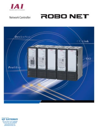
The document describes RoboNet, a new type of network controller unit that can operate robot cylinders via a field network. RoboNet greatly reduces wiring time and effort compared to conventional controllers by connecting components with one cable, simplifying installation. It utilizes small, compact controller units that connect via DIN rail and can move robots by directly specifying numeric movement values via the field network.

Recommended
More Related Content
What's hot
What's hot (17)
Viewers also liked
Viewers also liked (17)
Similar to Iai robonet controller_specsheet
Similar to Iai robonet controller_specsheet (20)
More from Electromate
More from Electromate (20)
Iai robonet controller_specsheet
- 1. 1 www.intelligentactuator.com Network Controller Network Controller Network Controller www.intelligentactuator.com W-1 Network Controller www.intelligentactuator.com Sold & Serviced By: ELECTROMATE Toll Free Phone (877) SERVO98 Toll Free Fax (877) SERV099 www.electromate.com sales@electromate.com
- 2. Greatly reduces time and eort of wiring and installation Newly Reduced wiring By connecting each line of the I/O cable to lines wired to the PLC terminals with the eld network, wiring processing is completed with one dedicated cable. Also, since the unit can be coupled by just connecting with the unit connection board, the controller wiring work is greatly simplied. Newly Reduced wiring By connecting each line of the I/O cable to lines wired to the PLC terminals with the eld network, wiring processing is completed with one dedicated cable. Also, since the unit can be coupled by just connecting with the unit connection board, the controller wiring work is greatly simplied. RoboNet is a new type of controller unit that can freely operate robot cylinders via a eld network. This makes it possible to greatly reduce the time and eort of wiring installation compared to conventional controllers by reducing wiring, making the controller smaller, and using DIN rail installation. RoboNet is a new type of controller unit that can freely operate robot cylinders via a eld network. This makes it possible to greatly reduce the time and eort of wiring installation compared to conventional controllers by reducing wiring, making the controller smaller, and using DIN rail installation. 1 1 Press t B 2 3 Field network DeviceNet/CC-Link/ProBus Press t B 4 1 Operation Operation Operation PLC Part conveyance A Part conveyance A Part conveyance B Part conveyance B Part conveyance C Part conveyance C Press t A Ejection Press t B Ejection Move position/velocity/acceleration and other data PLC Field network DeviceNet CC-Link ProBus 1 2 3 Part conveyance A Part conveyance B Press t A Part conveyance C Press t B Ejection Robonet communication connection board (See Page 10.) Robonet communication connection board (See Page 10.) Power supply connection board (See Page 10.) Terminal resistance board (See Page 10.) Terminal resistance board (See Page 10.) (Coupling section within RoboNet unit) Press t A 1 Greatly reduces time and eort of wiring and installation 1 2 3 5 6 2 3 Field network DeviceNet/CC-Link/ProBus Operation Operation Operation PLC Part conveyance A Part conveyance A Part conveyance B Part conveyance B Part conveyance C Part conveyance C Press t A Ejection Press t B Ejection Move position/velocity/acceleration and other data PLC Field network DeviceNet CC-Link ProBus 1 2 3 Part conveyance A Part conveyance B Press t A Part conveyance C Press t B Ejection Power supply connection board (See Page 10.) (Coupling section within RoboNet unit) Press t A 1 ELECTROMATE Sold Serviced By: Toll Free Phone (877) SERVO98 Toll Free Fax (877) SERV099 www.electromate.com sales@electromate.com
- 3. Newly Developed Network Controller Arrives! 3 34mm 3 34mm Can operate up to 16 axes 4 Up to 16 controller units can be connected to one Can operate up to 16 axes 4 Up to 16 controller units can be connected to one communications unit (GatewayR unit). One can also freely mix and connect RACON units (RCA controllers) and RPCON units (RCP2 controllers). Communications Unit 2 communications unit (GatewayR unit). One can also freely mix and connect RACON units (RCA controllers) and RPCON units (RCP2 controllers). Simple absolute specications that do not require a return to home position The simple absolute R unit makes it possible to operate incremental specication axes without returning to the home position. By mounting a simple absolute R unit on a RACON unit (RCA controller)/RPCON unit (RCP2 controller), the actuator encoder data is backed up even if the power is cut o. 5 The robot can be moved by directly specifying numeric values for the move position/velocity/ acceleration and other data. Besides the conventional method of moving the robot to pre-taught positions it is also possible to operate the robot by sending information as a string of numeric data that contains position, velocity, acceleration, etc. values. This is eective for cases such as when themove position changes with each piece or when one wants to move the robot to an arbitrary position. 2 Ultra-compact Each unit is an ultra-compact size of 34mm wide by 100mm high x 73 mm deep. Also, since there is no base unit and the main unit is coupled with connectors, the controller takes up little space for installation even if there aremany units. 100mm DIN rail installation The controller is installed with DIN rails, so it can be fastened and removed with one touch. 6 Controller unit Up to 16 units can be connected RACON RPCON Standard controller (ACON/PCON) Controller unit Up to 16 units can be connected Standard controller (ACON/PCON) Simple absolute R unit ROBONET controller Position specication movement Direct numeric value specication movement Velocity/acceleration specication Current value output ○ ○ ○ ○ ○ △ (Not possible with PIO) (Possible with serial communications) * RoboNet operates via the eld network; the standard controller operates with PIO. 2 Newly Developed Network Controller Arrives! Simple absolute specications that do not require a return to home position The simple absolute R unit makes it possible to operate incremental specication axes without returning to the home position. By mounting a simple absolute R unit on a RACON unit (RCA controller)/RPCON unit (RCP2 controller), the actuator encoder data is backed up even if the power is cut o. 5 The robot can be moved by directly specifying numeric values for the move position/velocity/ acceleration and other data. Besides the conventional method of moving the robot to pre-taught positions it is also possible to operate the robot by sending information as a string of numeric data that contains position, velocity, acceleration, etc. values. This is eective for cases such as when themove position changes with each piece or when one wants tomove the robot to an arbitrary position. 2 Ultra-compact Each unit is an ultra-compact size of 34mmwide by 100mmhigh x 73mmdeep. Also, since there is no base unit and the main unit is coupled with connectors, the controller takes up little space for installation even if there aremany units. 100mm DIN rail installation The controller is installedwith DIN rails, so it can be fastened and removedwith one touch. 6 Ejection Communications Unit 2 RACON RPCON Simple absolute R unit ROBONET controller Position specication movement Direct numeric value specicationmovement Velocity/acceleration specication Current value output ○ ○ ○ ○ ○ △ (Not possible with PIO) (Possible with serial communications) board * RoboNet operates via the eld network; the standard controller operates with PIO. 2 Sold Serviced By: ELECTROMATE Toll Free Phone (877) SERVO98 Toll Free Fax (877) SERV099 www.electromate.com sales@electromate.com
- 4. System conguration/component units RoboNet System conguration/component units RoboNet System conguration/component units RoboNet System conguration Operating List System conguration Operating List System conguration Operating List User's manual The RoboNet user's manual comes with the RoboNet not as a printed document, but as a CD-ROM. You can also download the user's manual from our homepage. PLC Teaching box (option) (Model: CON-T/RCM-E/RCM-P) (See Page 9.) PC software (option) RS232 connection board (Model: RCM-101-MW) USB connection board (Model: RCM-101-USB) (See Page 9.) 24 VDC power supply (Model: PS-241 (100V input)) (Model: PS-242 (200V input)) (See Page 9.) ・DeviceNet ・CC-Link ・ProBus ・DeviceNet ・CC-Link ・ProBus ・DeviceNet ・CC-Link ・ProBus * When an actuator is used with the simple absolute specication, a simple absolute R is mounted and the encoder cable is connected to the simple absolute R unit side. * When an actuator is used with the simple absolute specication, a simple absolute R is mounted and the encoder cable is connected to the simple absolute R unit side. * When an actuator is used with the simple absolute specication, a simple absolute R is mounted and the encoder cable is connected to the simple absolute R unit side. Encoder cable (attached to actuator) (Model: CB-RCP2-PA) (See Page 10.) Encoder cable (attached to actuator) (Model: CB-RCP2-PA) (See Page 10.) Encoder cable (attached to actuator) (Model: CB-RCP2-PA) (See Page 10.) Motor cable (attached to actuator) (Model: CB-RCP2-MA) See Page 10.) Encoder cable (attached to actuator) (Model: CB-ACS-PA) (See Page 10.) Encoder cable (attached to actuator) (Model: CB-ACS-PA) (See Page 10.) Encoder cable (attached to actuator) (Model: CB-ACS-PA) (See Page 10.) Field network Field network Field network Motor cable (attached to actuator) (Model: CB-ACS-MA) (See Page 10.) Actuator RCP2 series Actuator RCP2 series Actuator RCP2 series Actuator RCA series Component unit/ordering method explanation Unit name Contents See Page _ Unit name Contents See Page _ Unit name Contents See Page _ Simple absolute R unit This unit is for connection to the eld network. There are four types to select from: DeviceNet/CC-Link/ProBus/SIO. * This unit is a required unit for using RoboNet. This is the controller unit for operating an RCA actuator. (Each actuator axis requires one unit.) The standard specications are the incremental specications, but this unit can be used with the simple absolute specications by just combiningwith a simple absolute R unit. This is the controller unit for operating an RCP2 actuator. (Each actuator axis requires one unit.) The standard specications are the incremental specications, but this unit can be used with the simple absolute specications by just combiningwith a simple absolute R unit. This is the backup battery unit for holding the actuator encoder datawhen the power is switchedO. P5 P6 P7 P7 Gateway RACON RPCON P8 R unit unit unit Simple absolute R unit Gateway R unit RACON unit RPCON unit It can Use Number Movement Direct Direct Direct Pressing Completion Zone Position Teaching Jog Incremental Status Current Alarm Velocity Maximum Number * The by For RoboNet, you order the required units individually and use them together freely. Even if you want to add actuators later, you can do so simply by ordering additional RACON/RPCON units. ■ Order methodRoboNet is used by ordering the necessary units one by one and using them together. This means you can add or change units afterwards. (Order example) Operating the two actuator axes below via CC-Link The models for operating with absolute specications are as follows. Actuator 1 Model/ RCA-RA3D~ Actuator 2 Model/ RCP2-RA3C~ CC-Link Gateway unit Model/ RGW-CC Actuator 1 Controller unit Model/ RACON-20 Simple absolute unit Model/ RABU Simple absolute unit Model/ RABU Actuator 2 Controller unit Model/ RPCON-28SP 3 User's manual The RoboNet user's manual comes with the RoboNet not as a printed document, but as a CD-ROM. You can also download the user's manual from our homepage. PLC Teaching box (option) (Model: CON-T/RCM-E/RCM-P) (See Page 9.) PC software (option) RS232 connection board (Model: RCM-101-MW) USB connection board (Model: RCM-101-USB) (See Page 9.) 24 VDC power supply (Model: PS-241 (100V input)) (Model: PS-242 (200V input)) (See Page 9.) Motor cable (attached to actuator) (Model: CB-RCP2-MA) (See Page 10.) Motor cable (attached to actuator) (Model: CB-ACS-MA) (See Page 10.) Actuator RCA series Component unit/ordering method explanation Simple absolute R unit This unit is for connection to the eld network. There are four types to select from: DeviceNet/CC-Link/ProBus/SIO. * This unit is a required unit for using RoboNet. This is the controller unit for operating an RCA actuator. (Each actuator axis requires one unit.) The standard specications are the incremental specications, but this unit can be used with the simple absolute specications by just combining with a simple absolute R unit. This is the controller unit for operating an RCP2 actuator. (Each actuator axis requires one unit.) The standard specications are the incremental specications, but this unit can be used with the simple absolute specications by just combining with a simple absolute R unit. This is the backup battery unit for holding the actuator encoder data when the power is switched O. P5 P6 P7 P7 Gateway RACON RPCON P8 R unit unit unit Simple absolute R unit Gateway R unit RACON unit RPCON unit It can Use Number Movement Direct Direct Direct Pressing Completion Zone Position Teaching Jog Incremental Status Current Alarm Velocity Maximum Number * The by For RoboNet, you order the required units individually and use them together freely. Even if you want to add actuators later, you can do so simply by ordering additional RACON/RPCON units. ■ Order methodRoboNet is used by ordering the necessary units one by one and using them together. This means you can add or change units afterwards. (Order example) Operating the two actuator axes below via CC-Link The models for operating with absolute specications are as follows. Actuator 1 Model/ RCA-RA3D~ Actuator 2 Model/ RCP2-RA3C~ CC-Link Gateway unit Model/ RGW-CC Actuator 1 Controller unit Model/ RACON-20 Simple absolute unit Model/ RABU Simple absolute unit Model/ RABU Actuator 2 Controller unit Model/ RPCON-28SP 3 User's manual The RoboNet user's manual comes with the RoboNet not as a printed document, but as a CD-ROM. You can also download the user's manual from our homepage. PLC Teaching box (option) (Model: CON-T/RCM-E/RCM-P) (See Page 9.) PC software (option) RS232 connection board (Model: RCM-101-MW) USB connection board (Model: RCM-101-USB) (See Page 9.) 24 VDC power supply (Model: PS-241 (100V input)) (Model: PS-242 (200V input)) (See Page 9.) Motor cable (attached to actuator) (Model: CB-RCP2-MA) (See Page 10.) Motor cable (attached to actuator) (Model: CB-ACS-MA) (See Page 10.) Actuator RCA series Component unit/ordering method explanation Simple absolute R unit This unit is for connection to the eld network. There are four types to select from: DeviceNet/CC-Link/ProBus/SIO. * This unit is a required unit for using RoboNet. This is the controller unit for operating an RCA actuator. (Each actuator axis requires one unit.) The standard specications are the incremental specications, but this unit can be used with the simple absolute specications by just combiningwith a simple absolute R unit. This is the controller unit for operating an RCP2 actuator. (Each actuator axis requires one unit.) The standard specications are the incremental specications, but this unit can be used with the simple absolute specications by just combiningwith a simple absolute R unit. This is the backup battery unit for holding the actuator encoder datawhen the power is switchedO. P5 P6 P7 P7 Gateway RACON RPCON P8 R unit unit unit Simple absolute R unit Gateway R unit RACON unit RPCON unit It can Use 1 2 3 Number Movement Direct Direct Direct Pressing Completion Zone Position Teaching Jog Incremental Status Current Alarm Velocity Maximum Number * The by For RoboNet, you order the required units individually and use them together freely. Even if you want to add actuators later, you can do so simply by ordering additional RACON/RPCON units. ■ Order methodRoboNet is used by ordering the necessary units one by one and using them together. This means you can add or change units afterwards. (Order example) Operating the two actuator axes below via CC-Link The models for operating with absolute specications are as follows. Actuator 1 Model/ RCA-RA3D~ Actuator 2 Model/ RCP2-RA3C~ CC-Link Gateway unit Model/ RGW-CC Actuator 1 Controller unit Model/ RACON-20 Simple absolute unit Model/ RABU Simple absolute unit Model/ RABU Actuator 2 Controller unit Model/ RPCON-28SP 3 ELECTROMATE Sold Serviced By: Toll Free Phone (877) SERVO98 Toll Free Fax (877) SERV099 www.electromate.com sales@electromate.com
- 5. Operating mode explanation List of Functions by Operating Mode Page _ P5 P6 P7 P7 P8 Operating mode explanation RoboNet operates under instructions received from the PLC via the eld network. It can be used switching among the following three operating modes. Use the operating mode that best suits the device operation details and control method. Name Contents This mode operates by specifying the position number. The position data, velocity, acceleration, etc. are input for each position ahead of time. Up to 768 positions can be registered. This mode operates by directly specifying only the position data and specifying other data – velocity, acceleration, position width, electrical current limit for pressing – with the position number. Up to 768 positions can be registered. This mode operates by directly specifying the numeric values for the position data, velocity, acceleration, position width, and electrical current limit for pressing. There is no limit on the number of position points that can be specied numerically. Positioner mode Simple direct value mode Direct numeric value specication 1 2 3 Positioner mode Simple direct value mode Direct numeric value specication Number of positions registered Movement by specifying position number Direct specication of position data Direct specication of velocity and acceleration Direct specication of positioning width Pressing operation Completion position number monitor Zone output monitor Position zone output monitor Teaching functions Jog operations Incremental moves Status signal monitor (*) Current position monitor (*) Alarm code monitor (*) Velocity and electric current monitor (*) Maximum value for specication of position data Number of axes that can be connected 768 points ○ × ×(Speciedwith position table) ×(Speciedwith position table) ○(Speciedwith position table) ○ ○ ○ ○ ○ ○ ○ ○ ○ × 9999.99mm 16 768 points ○ ? ×(Speciedwith position table) ×(Speciedwith position table) ○(Speciedwith position table) ○ ○ ○ × ○ ○ ○ ○ ○ × 9999.99mm 16 × ○ ○ ○ ○ × ○ × × ○ ○ ○ ○ ○ ○ 9999.99mm 8 * The status signal monitor, current position monitor, alarm code monitor, and velocity and electric current monitor can monitor by accessing each address of the GatewayR unit from the PLC. follows. unit 4 Operating mode explanation List of Functions by Operating Mode Page _ P5 P6 P7 P7 P8 Operating mode explanation RoboNet operates under instructions received from the PLC via the eld network. It can be used switching among the following three operating modes. Use the operating mode that best suits the device operation details and control method. Name Contents This mode operates by specifying the position number. The position data, velocity, acceleration, etc. are input for each position ahead of time. Up to 768 positions can be registered. This mode operates by directly specifying only the position data and specifying other data – velocity, acceleration, position width, electrical current limit for pressing – with the position number. Up to 768 positions can be registered. This mode operates by directly specifying the numeric values for the position data, velocity, acceleration, position width, and electrical current limit for pressing. There is no limit on the number of position points that can be specied numerically. Positioner mode Simple direct value mode Direct numeric value specication 1 2 3 Positioner mode Simple direct value mode Direct numeric value specication Number of positions registered Movement by specifying position number Direct specication of position data Direct specication of velocity and acceleration Direct specication of positioning width Pressing operation Completion position number monitor Zone output monitor Position zone output monitor Teaching functions Jog operations Incremental moves Status signal monitor (*) Current position monitor (*) Alarm code monitor (*) Velocity and electric current monitor (*) Maximum value for specication of position data Number of axes that can be connected 768 points ○ × ×(Speciedwith position table) ×(Speciedwith position table) ○(Speciedwith position table) ○ ○ ○ ○ ○ ○ ○ ○ ○ × 9999.99mm 16 768 points ○ ? ×(Speciedwith position table) ×(Speciedwith position table) ○(Speciedwith position table) ○ ○ ○ × ○ ○ ○ ○ ○ × 9999.99mm 16 × ○ ○ ○ ○ × ○ × × ○ ○ ○ ○ ○ ○ 9999.99mm 8 * The status signal monitor, current position monitor, alarm code monitor, and velocity and electric current monitor can monitor by accessing each address of the GatewayR unit from the PLC. follows. unit 4 Operating mode explanation List of Functions by Operating Mode Operating mode explanation RoboNet operates under instructions received from the PLC via the eld network. It can be used switching among the following three operating modes. Use the operating mode that best suits the device operation details and control method. Name Contents This mode operates by specifying the position number. The position data, velocity, acceleration, etc. are input for each position ahead of time. Up to 768 positions can be registered. This mode operates by directly specifying only the position data and specifying other data – velocity, acceleration, position width, electrical current limit for pressing – with the position number. Up to 768 positions can be registered. This mode operates by directly specifying the numeric values for the position data, velocity, acceleration, position width, and electrical current limit for pressing. There is no limit on the number of position points that can be specied numerically. Positioner mode Simple direct value mode Direct numeric value specication 1 2 3 Positioner mode Simple direct value mode Direct numeric value specication Number of positions registered Movement by specifying position number Direct specication of position data Direct specication of velocity and acceleration Direct specication of positioning width Pressing operation Completion position number monitor Zone output monitor Position zone output monitor Teaching functions Jog operations Incremental moves Status signal monitor (*) Current position monitor (*) Alarm code monitor (*) Velocity and electric current monitor (*) Maximum value for specication of position data Number of axes that can be connected 768 points ○ × × (Specied with position table) ×(Specied with position table) ○ (Specied with position table) ○ ○ ○ ○ ○ ○ ○ ○ ○ × 9999.99mm 16 768 points ○ ? ×(Specied with position table) × (Specied with position table) ○ (Specied with position table) ○ ○ ○ × ○ ○ ○ ○ ○ × 9999.99mm 16 × ○ ○ ○ ○ × ○ × × ○ ○ ○ ○ ○ ○ 9999.99mm 8 * The status signal monitor, current position monitor, alarm code monitor, and velocity and electric current monitor can monitor by accessing each address of the GatewayR unit from the PLC. 4 Operating mode explanation of Functions by Operating Mode Operating mode explanation RoboNet operates under instructions received from the PLC via the eld network. be used switching among the following three operating modes. operating mode that best suits the device operation details and control method. Name Contents This mode operates by specifying the position number. The position data, velocity, acceleration, etc. are input for each position ahead of time. Up to 768 positions can be registered. This mode operates by directly specifying only the position data and specifying other data – velocity, acceleration, position width, electrical current limit for pressing – with the position number. Up to 768 positions can be registered. This mode operates by directly specifying the numeric values for the position data, velocity, acceleration, position width, and electrical current limit for pressing. There is no limit on the number of position points that can be specied numerically. Positioner mode Simple direct value mode Direct numeric value specication Positioner mode Simple direct value mode Direct numeric value specication of positions registered Movement by specifying position number specication of position data specication of velocity and acceleration specication of positioning width operation Completion position number monitor output monitor zone output monitor Teaching functions operations Incremental moves signal monitor (*) position monitor (*) code monitor (*) and electric current monitor (*) Maximum value for specication of position data of axes that can be connected 768 points ○ × ×(Speciedwith position table) ×(Speciedwith position table) ○(Speciedwith position table) ○ ○ ○ ○ ○ ○ ○ ○ ○ × 9999.99mm 16 ? ×(Speciedwith position table) edwith edwith × × ○ ○ ○ ○ × × ○ 8 status signal monitor, current position monitor, alarm code monitor, and velocity and electric current monitor can monitor accessing each address of the GatewayR unit from the PLC. 4 Sold Serviced By: ELECTROMATE Toll Free Phone (877) SERVO98 Toll Free Fax (877) SERV099 www.electromate.com sales@electromate.com
- 6. Component unit explanation (GatewayR unit) This is the communications unit for operating RoboNet via DeviceNet. Component unit explanation (GatewayR unit) This is the communications unit for operating RoboNet via DeviceNet. Component unit explanation (GatewayR unit) GatewayR unit (DeviceNet specications) This is the communications unit for operating RoboNet via DeviceNet. Model RGW-DV Specications Item Specications Specications Item Specications Specications Item Specications Specications Communications standard Communications specications CC-Link specications DeviceNet specications Environmental CC-Link specications conditions DeviceNet specications Environmental conditions Communications speed DC24V ±10% 600 mA max. Uses DeviceNet 2.0 certied interface module Group 2 only server Insulated node operating with network power supply Bit strobe Polling Cyclic 500k/250k/125kbps (switched with dedicated software) Communications speed Maximum network length Maximumbranch line length Total branch line length 500kbps 250kbps 125kbps 100m 250m 500m 6m 39m 78m 156m 0~40℃ 95% RH max. (no condensation allowed) Theremust be no corrosive gas, combustible gas, oilmist, or dust. IP20 140g Power supply Current consumption Item Master-satellite Connection Communications Cable length (※1) Number of nodes occupied Note: When thick DeviceNet cable is used 1 node Usage ambient temperature Usage ambient humidity Usage atmosphere Protection rank Weight Accessories * 1 For T branch communications, refer to the user's manuals for the master unit and for the PLC used. Pin colors Explanation Pin colors Explanation Pin colors Explanation GatewayR unit CC-Link specications Compatible wire for cable side connector Compatible wire for cable side connector Compatible Item Item wire for cable Contents side Contents connector Item Contents This is the communications unit for operating RoboNet via CC-Link. Model RGW-CC Specications Network connector Black Blue - White Red Power cable - side Communications data Low side Shield Communications data High side Power cable + side Compatible wire diameter Peeled wire length Braided wire AWG24-12 (0.2~2.5 mm2) 7mm Gateway side con n:ector MSTBA2.5/5-G-5.08 ABGY AU (Made by Phoenix Contact) Cable side connector MSTB2.5/5-ST-5.08 ABGY AU (Made by Phoenix Contact) = Standard accessory Network connector Item Specications Specications Item Specications Specications Item Specications Specications Signal name Explanation Signal name Explanation Signal name Explanation DA DB DG SLD FG Communications line A Communications line B Ground Connect the shield and cable shield to the frame ground and chassis. Connect the frame ground to the shield and the chassis Compatible wire for cable side connector Compatible wire for cable side connector Compatible wire for cable side connector Item Contents Item Contents Item Contents Compatible wire diameter Peeled wire length Braided wire AWG24-12 (0.2~2.5 mm2) 7mm Gateway side connector MSTBA2.5/5-G-5.08AU (Made by Phoenix Contact) IP20 140g Communications standard Communications speed Communications technique Synchronization technique Encoding technique Transmission path format Transmission format Error control technique Number of stations occupied Communications cable length (※2) Communication cable Usage ambient temperature Usage ambient humidity Usage atmosphere Protection rank Weight Accessories DC24V ±10% 600 mA max. CC-Link Ver2.0(※1) 10M/5M/2.5M/625k/156kbps (switched with dedicated software) Broadcast polling technique Frame synchronization technique NRZI Bus format (complies with EIA RS485) Complies with HDLC CRC(X16+X12+X5+1) Remote device stations 1x 4 stations, 4x 2 stations, 8x 2 stations Special CC-Link cable 0~40℃ 95% RH max. (no condensation allowed) Theremust be no corrosive gas, combustible gas, oilmist, or dust. Power supply Current consumption Item *1 Certication acquired *2 For T branch communications, refer to the user's manuals for the master unit and for the PLC used. Communications speed (bps) Total cable length (m) 10M 5M 2.5M 625k 156k 100 160 400 900 1200 Cable side connector MSTB2.5/5-ST-5.08 ABGY AU (Made by Phoenix Contact) = Standard accessory Network Gateway D-Socket Network Gateway MC1.5/(Cable MC1.5/(= ■ Component unit explanation Terminal resistance board (Model TN-1) Network connector/emergency stop connector Terminal resistance board (Model TN-1) Network connector/emergency stop connector Terminal resistance cable (110/130) Black Blue White Red DA DB DG SLD FG 5 GatewayR unit (DeviceNet specications) Model RGW-DV Specications Communications standard Communications specications CC-Link specications DeviceNet specications Environmental CC-Link specications conditions DeviceNet specications Environmental conditions Communications speed DC24V ±10% 600 mA max. Uses DeviceNet 2.0 certied interface module Group 2 only server Insulated node operating with network power supply Bit strobe Polling Cyclic 500k/250k/125kbps (switched with dedicated software) Communications speed Maximum network length Maximum branch line length Total branch line length 500kbps 250kbps 125kbps 100m 250m 500m 6m 39m 78m 156m 0~40℃ 95% RH max. (no condensation allowed) There must be no corrosive gas, combustible gas, oil mist, or dust. IP20 140g Power supply Current consumption Item Master-satellite Connection Communications Cable length (※1) Number of nodes occupied Note: When thick DeviceNet cable is used 1 node Usage ambient temperature Usage ambient humidity Usage atmosphere Protection rank Weight Accessories * 1 For T branch communications, refer to the user's manuals for the master unit and for the PLC used. GatewayR unit CC-Link specications This is the communications unit for operating RoboNet via CC-Link. Model RGW-CC Specications Network connector Black Blue - White Red Power cable - side Communications data Low side Shield Communications data High side Power cable + side Compatible wire diameter Peeled wire length Braided wire AWG24-12 (0.2~2.5 mm2) 7mm Gateway side con n:ector MSTBA2.5/5-G-5.08 ABGY AU (Made by Phoenix Contact) Cable side connector MSTB2.5/5-ST-5.08 ABGY AU (Made by Phoenix Contact) = Standard accessory Network connector DA DB DG SLD FG Communications line A Communications line B Ground Connect the shield and cable shield to the frame ground and chassis. Connect the frame ground to the shield and the chassis Compatible wire diameter Peeled wire length Braided wire AWG24-12 (0.2~2.5 mm2) 7mm Gateway side connector MSTBA2.5/5-G-5.08AU (Made by Phoenix Contact) IP20 140g Communications standard Communications speed Communications technique Synchronization technique Encoding technique Transmission path format Transmission format Error control technique Number of stations occupied Communications cable length (※2) Communication cable Usage ambient temperature Usage ambient humidity Usage atmosphere Protection rank Weight Accessories DC24V ±10% 600 mA max. CC-Link Ver2.0(※1) 10M/5M/2.5M/625k/156kbps (switched with dedicated software) Broadcast polling technique Frame synchronization technique NRZI Bus format (complies with EIA RS485) Complies with HDLC CRC(X16+X12+X5+1) Remote device stations 1x 4 stations, 4x 2 stations, 8x 2 stations Special CC-Link cable 0~40℃ 95% RH max. (no condensation allowed) There must be no corrosive gas, combustible gas, oil mist, or dust. Power supply Current consumption Item *1 Certication acquired *2 For T branch communications, refer to the user's manuals for the master unit and for the PLC used. Communications speed (bps) Total cable length (m) 10M 5M 2.5M 625k 156k 100 160 400 900 1200 Cable side connector MSTB2.5/5-ST-5.08 ABGY AU (Made by Phoenix Contact) = Standard accessory ■ Component unit explanation Terminal resistance board (Model TN-1) Network connector/emergency stop connector Terminal resistance board (Model TN-1) Network connector/emergency stop connector Terminal resistance cable (110/130) Black Blue White Red DA DB DG SLD FG 5 GatewayR unit (DeviceNet specications) Model RGW-DV Specications Communications standard Communications specications CC-Link specications DeviceNet specications Environmental CC-Link specications conditions DeviceNet specications Environmental conditions Communications speed DC24V ±10% 600 mA max. Uses DeviceNet 2.0 certied interface module Group 2 only server Insulated node operating with network power supply Bit strobe Polling Cyclic 500k/250k/125kbps (switched with dedicated software) Communications speed Maximum network length Maximumbranch line length Total branch line length 500kbps 250kbps 125kbps 100m 250m 500m 6m 39m 78m 156m 0~40℃ 95% RH max. (no condensation allowed) Theremust be no corrosive gas, combustible gas, oilmist, or dust. IP20 140g Power supply Current consumption Item Master-satellite Connection Communications Cable length (※1) Number of nodes occupied Note: When thick DeviceNet cable is used 1 node Usage ambient temperature Usage ambient humidity Usage atmosphere Protection rank Weight Accessories * 1 For T branch communications, refer to the user's manuals for the master unit and for the PLC used. GatewayR unit CC-Link specications This is the communications unit for operating RoboNet via CC-Link. Model RGW-CC Specications Network connector Black Blue - White Red Power cable - side Communications data Low side Shield Communications data High side Power cable + side Compatible wire diameter Peeled wire length Braided wire AWG24-12 (0.2~2.5 mm2) 7mm Gateway side con n:ector MSTBA2.5/5-G-5.08 ABGY AU (Made by Phoenix Contact) Cable side connector MSTB2.5/5-ST-5.08 ABGY AU (Made by Phoenix Contact) = Standard accessory Network connector DA DB DG SLD FG Communications line A Communications line B Ground Connect the shield and cable shield to the frame ground and chassis. Connect the frame ground to the shield and the chassis Compatible wire diameter Peeled wire length Braided wire AWG24-12 (0.2~2.5 mm2) 7mm Gateway side connector MSTBA2.5/5-G-5.08AU (Made by Phoenix Contact) IP20 140g Communications standard Communications speed Communications technique Synchronization technique Encoding technique Transmission path format Transmission format Error control technique Number of stations occupied Communications cable length (※2) Communication cable Usage ambient temperature Usage ambient humidity Usage atmosphere Protection rank Weight Accessories DC24V ±10% 600 mA max. CC-Link Ver2.0(※1) 10M/5M/2.5M/625k/156kbps (switched with dedicated software) Broadcast polling technique Frame synchronization technique NRZI Bus format (complies with EIA RS485) Complies with HDLC CRC(X16+X12+X5+1) Remote device stations 1x 4 stations, 4x 2 stations, 8x 2 stations Special CC-Link cable 0~40℃ 95% RH max. (no condensation allowed) Theremust be no corrosive gas, combustible gas, oilmist, or dust. Power supply Current consumption Item *1 Certication acquired *2 For T branch communications, refer to the user's manuals for the master unit and for the PLC used. Communications speed (bps) Total cable length (m) 10M 5M 2.5M 625k 156k 100 160 400 900 1200 Cable side connector MSTB2.5/5-ST-5.08 ABGY AU (Made by Phoenix Contact) = Standard accessory Network Gateway D-Socket Network Gateway MC1.5/(Made Cable MC1.5/(Made = ■ Component unit explanation Terminal resistance board (Model TN-1) Network connector/emergency stop connector Terminal resistance board (Model TN-1) Network connector/emergency stop connector Terminal resistance cable (110/130) Black Blue White Red DA DB DG SLD FG 5 Sold Serviced By: ELECTROMATE Toll Free Phone (877) SERVO98 Toll Free Fax (877) SERV099 www.electromate.com sales@electromate.com
- 7. Component unit explanation (GatewayR unit) GatewayR unit (ProBus specications) Component unit explanation (GatewayR unit) Component unit explanation (GatewayR unit) This is the communications unit for operating RoboNet via ProBus. Model RGW-PR Specications Item Specications Specications DC24V ±10% 600 mA max. DP satellite 9.6kbps~12Mbps Communications speed 9.6kbps 500kbps 1.5Mbps 3Mbps 12Mbps 1500m 400m 200m 200m 100m 0~40℃ 95% RH max. (no condensation allowed) There must be no corrosive gas, combustible gas, oil mist, or dust. IP20 140g Power supply Current consumption Item Usage ambient temperature Usage ambient humidity Usage atmosphere Protection rank Weight Accessories Communications speed Communications speed Pin No. Signal name Explanation Pin No. Explanation 3 4 5 Pin No. Signal name Explanation Pin No. Explanation B-Line B-Line Pin No. Signal name Explanation Pin No. Explanation RTS GND Communications line B (RS485) Request to send Signal ground (insulated) 5 1 5 1 5 1 9 6 3 4 5 RTS GND 9 6 3 4 5 B-Line RTS GND 9 6 GatewayR unit SIO specications +5V +5V A-Line Shield +5V output (insulated) Communications line A (RS485) The cable shield is connected with the chassis. A-Line Shield Communications line B (RS485) Request to send Signal ground (insulated) +5V output (insulated) Communications line A (RS485) The cable shield is connected with the chassis. +5V A-Line Shield Communications line B (RS485) Request to send Signal ground (insulated) +5V output (insulated) Communications line A (RS485) The cable shield is connected with the chassis. This is the communications unit for operating RoboNet with serial communications from an XSEL controller (*1) or Modbus communications unit. *1 A unit with XSEL Gateway functions is scheduled for release soon. Model RGW-SIO Specications Network connector * The partner side connector (D-sub 9-pin connector) does not come as an accessory. * Pins 1, 2, 7, and 9 are not connected. Gateway side connector: D-Sub 9-pin connector Socket side Network connector Item Specications Specications Item Specications Specications Item Specications Specications Signal name Explanation SA Signal name Explanation SB SG FG Signal name Explanation Communications line A (+ side) Communications line B (- side) Signal ground The frame ground is connected with the chassis. Compatible wire for cable side connector Compatible wire for cable side connector Compatible wire for cable side connector Item Contents Item Contents Compatible wire diameter Peeled wire length Braided wire AWG28-16 (0.14~1.5 mm2) 7mm Gateway side conn e:ctor MC1.5/4-G-3.5 (Made by Phoenix Contact) Cable side connector: MC1.5/4-ST-3.5 (Made by Phoenix Contact) = Standard accessory Weight Accessories Communications format Communications technique Communications speed Cable length Recommended cable Usage ambient temperature Usage ambient humidity Usage atmosphere Protection rank DC24V ±10% 600 mA max. RS485 compliant (Modbus protocol) 1:1 communication connection Stop-start system Half duplex 230.4 kbps max. 100 m max. 2-pair twisted pair cable (with shield) 0~40℃ 95% RH max. (no condensation allowed) There must be no corrosive gas, combustible gas, oil mist, or dust. IP20 140g Power supply Current consumption Item 6 8 Housing Signal name RS485 compliant Terminal resistance board (220 ) built in Terminal resistance board (Model TN-1) Emergency stop connector Terminal resistance board (Model TN-1) Network connector/emergency stop connector ProBus specications Environmental conditions Communications standard Communications cable length SIO specications Environmental conditions FG SG SB SA 6 branch length 39m 78m 156m dust. connector stations 156k 1200 156k 1200 dust. GatewayR unit (ProBus specications) This is the communications unit for operating RoboNet via ProBus. Model RGW-PR Specications Item Specications Specications DC24V ±10% 600 mA max. DP satellite 9.6kbps~12Mbps 9.6kbps 500kbps 1.5Mbps 3Mbps 12Mbps 1500m 400m 200m 200m 100m 0~40℃ 95% RH max. (no condensation allowed) Theremust be no corrosive gas, combustible gas, oilmist, or dust. IP20 140g Power supply Current consumption Item Usage ambient temperature Usage ambient humidity Usage atmosphere Protection rank Weight Accessories GatewayR unit SIO specications This is the communications unit for operating RoboNet with serial communications from an XSEL controller (*1) or Modbus communications unit. *1 A unit with XSEL Gateway functions is scheduled for release soon. Model RGW-SIO Specications Network connector * The partner side connector (D-sub 9-pin connector) does not come as an accessory. * Pins 1, 2, 7, and 9 are not connected. Gateway side connector: D-Sub 9-pin connector Socket side Network connector SA SB SG FG Communications line A (+ side) Communications line B (- side) Signal ground The frame ground is connected with the chassis. Compatible wire diameter Peeled wire length Braided wire AWG28-16 (0.14~1.5 mm2) 7mm Gateway side conne:ctor MC1.5/4-G-3.5 (Made by Phoenix Contact) Cable side connector: MC1.5/4-ST-3.5 (Made by Phoenix Contact) = Standard accessory Weight Accessories Communications format Communications technique Communications speed Cable length Recommended cable Usage ambient temperature Usage ambient humidity Usage atmosphere Protection rank DC24V ±10% 600 mA max. RS485 compliant (Modbus protocol) 1:1 communication connection Stop-start system Half duplex 230.4 kbps max. 100 m max. 2-pair twisted pair cable (with shield) 0~40℃ 95% RH max. (no condensation allowed) Theremust be no corrosive gas, combustible gas, oilmist, or dust. IP20 140g Power supply Current consumption Item 6 8 Housing Signal name RS485 compliant Terminal resistance board (220 ) built in Terminal resistance board (Model TN-1) Emergency stop connector Terminal resistance board (Model TN-1) Network connector/emergency stop connector ProBus specications Environmental conditions Communications standard Communications cable length SIO specications Environmental conditions FG SG SB SA 6 branch length dust. connector stations dust. GatewayR unit (ProBus specications) This is the communications unit for operating RoboNet via ProBus. Model RGW-PR Specications Item Specications Specications DC24V ±10% 600 mA max. DP satellite 9.6kbps~12Mbps 9.6kbps 500kbps 1.5Mbps 3Mbps 12Mbps 1500m 400m 200m 200m 100m 0~40℃ 95% RH max. (no condensation allowed) Theremust be no corrosive gas, combustible gas, oilmist, or dust. IP20 140g Power supply Current consumption Item Usage ambient temperature Usage ambient humidity Usage atmosphere Protection rank Weight Accessories GatewayR unit SIO specications This is the communications unit for operating RoboNet with serial communications from an XSEL controller (*1) or Modbus communications unit. *1 A unit with XSEL Gateway functions is scheduled for release soon. Model RGW-SIO Specications Network connector * The partner side connector (D-sub 9-pin connector) does not come as an accessory. * Pins 1, 2, 7, and 9 are not connected. Gateway side connector: D-Sub 9-pin connector Socket side Network connector SA SB SG FG Communications line A (+ side) Communications line B (- side) Signal ground The frame ground is connected with the chassis. Item Contents Compatible wire diameter Peeled wire length Braided wire AWG28-16 (0.14~1.5 mm2) 7mm Gateway side conne:ctor MC1.5/4-G-3.5 (Made by Phoenix Contact) Cable side connector: MC1.5/4-ST-3.5 (Made by Phoenix Contact) = Standard accessory Weight Accessories Communications format Communications technique Communications speed Cable length Recommended cable Usage ambient temperature Usage ambient humidity Usage atmosphere Protection rank DC24V ±10% 600 mA max. RS485 compliant (Modbus protocol) 1:1 communication connection Stop-start system Half duplex 230.4 kbps max. 100 m max. 2-pair twisted pair cable (with shield) 0~40℃ 95% RH max. (no condensation allowed) Theremust be no corrosive gas, combustible gas, oilmist, or dust. IP20 140g Power supply Current consumption Item 6 8 Housing Signal name RS485 compliant Terminal resistance board (220 ) built in Terminal resistance board (Model TN-1) Emergency stop connector Terminal resistance board (Model TN-1) Network connector/emergency stop connector ProBus specications Environmental conditions Communications standard Communications cable length SIO specications Environmental conditions FG SG SB SA 6 Sold Serviced By: ELECTROMATE Toll Free Phone (877) SERVO98 Toll Free Fax (877) SERV099 www.electromate.com sales@electromate.com
- 8. Component unit explanation (controller unit) Controller model Supported actuators Component unit explanation (controller unit) Controller model Supported actuators Component unit explanation (controller unit) RACON unit RCA series controller Controller model Supported actuators This is the controller unit for operating an RCA actuator with RoboNet. Specications Item General specications RCA-RA3□ / RG□3□ RCAW-RA3□ RCA-RA3□ / RG□ 3□ RCAW-RA3□ RPCON unit RCP2 series controller RCA-RA3□ / RG□3□ RCAW-RA3□ Environmental conditions Environmental conditions Environmental conditions This is the controller unit for operating an RCP2 actuator with RoboNet. Specications Specications Specications DC24V ±10% 5.1 A max. (depends on actuator) RCA series 768 points EEPROM Incremental encoder Brake release switch Model CB-ACS-MA Model CB-ACS-PA 0~50℃ 95% RH max. (no condensation allowed) There must be no corrosive gas, combustible gas, oil mist, or dust. IP20 200g RoboNet communication connection board (JB-1 model) Power supply connection board (PP-1 model) RCP2-GRM / GR3LS / GR3SS / RTB / RTC RCP2-GRM / GR3LS / GR3SS / RTB / RTC RCP2-GRM / GR3LS / GR3SS / RTB / RTC RCP2-SA5□ / SA6□ / SS7□ / BA6□ / BA7□ / RA4C / RG□4C /GR3LM / GR3SM RCP2CR-SA5C / SA6C / SS7C RCP2W-RA4C RCP2-SA5□ / SA6□ / SS7□ / BA6□ / BA7□ / RA4C / RG□4C /GR3LM / GR3SM RCP2CR-SA5C / SA6C / SS7C RCP2W-RA4C RCP2-SA5□ / SA6□ / SS7□ / BA6□ / BA7□ / RA4C / RG□4C /GR3LM / GR3SM RCP2CR-SA5C / SA6C / SS7C RCP2W-RA4C Item Specications Specications DC24V ±10% 2 A max. RCP2 series 768 points EEPROM Incremental encoder Brake release switch Model CB-RCP2-MA Model CB-RCP2-PA 0~50℃ 95% RH max. (no condensation allowed) There must be no corrosive gas, combustible gas, oil mist, or dust. IP20 200g RoboNet communication connection board (JB-1 model) Power supply connection board (PP-1 model) ■ Component unit explanation RCA-SA4□ / SS4□ / SA5□ / SS5□ / RA4□-20 / RG□4□-20 / A4R / A5R RCACR-SA4C / SA5□ RCAW-RA4□-20 RCA-SA6□ / SS6□ / RA4□-30 / RG□4□-30 / A6R RCACR-SA6□ RCAW-RA4□-30 RACON-20 RACON-20S RACON-30 Controller model Supported actuators RPCON-20P RPCON-28P RPCON-28SP RPCON-42P RPCON-56P RCP2-RA2C GRS RCP2-RA3C / RGD3C RCP2-SA7□ / SS8□ / RA6C / RG□6C / RCP2CR-SA7C / SS8C RCP2W-RA6C * This controller can also operate an old-type RCP2 actuator. (Please inquire for details.) Power supply Power supply capacity Operating actuator Number of positioning points Backup memory Position detection technique Electromagnetic brake forced release Motor cable Encoder cable Item Usage ambient temperature Usage ambient humidity Usage atmosphere Protection rank Weight Accessories General specications Power supply Power supply capacity Operating actuator Number of positioning points Backup memory Position detection technique Electromagnetic brake forced release Motor cable Encoder cable Item Environmental conditions Usage ambient temperature Usage ambient humidity Usage atmosphere Protection rank Weight Accessories 7 RACON unit RCA series controller This is the controller unit for operating an RCA actuator with RoboNet. Specications GatewayR RPCON unit RCP2 series controller This is the controller unit for operating an RCP2 actuator with RoboNet. Specications Simple External Item General specications Specications Specications DC24V ±10% 5.1 A max. (depends on actuator) RCA series 768 points EEPROM Incremental encoder Brake release switch Model CB-ACS-MA Model CB-ACS-PA 0~50℃ 95% RH max. (no condensation allowed) There must be no corrosive gas, combustible gas, oil mist, or dust. IP20 200g RoboNet communication connection board (JB-1 model) Power supply connection board (PP-1 model) Item Specications Specications DC24V ±10% 2 A max. RCP2 series 768 points EEPROM Incremental encoder Brake release switch Model CB-RCP2-MA Model CB-RCP2-PA 0~50℃ 95% RH max. (no condensation allowed) There must be no corrosive gas, combustible gas, oil mist, or dust. IP20 200g RoboNet communication connection board (JB-1 model) Power supply connection board (PP-1 model) ■ Component unit explanation RCA-SA4□ / SS4□ / SA5□ / SS5□ / RA4□-20 / RG□4□-20 / A4R / A5R RCACR-SA4C / SA5□ RCAW-RA4□-20 RCA-SA6□ / SS6□ / RA4□-30 / RG□4□-30 / A6R RCACR-SA6□ RCAW-RA4□-30 RACON-20 RACON-20S RACON-30 Controller model Supported actuators RPCON-20P RPCON-28P RPCON-28SP RPCON-42P RPCON-56P RCP2-RA2C / GRS RCP2-RA3C / RGD3C RCP2-SA7□ / SS8□ / RA6C / RG□6C / RCP2CR-SA7C / SS8C RCP2W-RA6C * This controller can also operate an old-type RCP2 actuator. (Please inquire for details.) Power supply Power supply capacity Operating actuator Number of positioning points Backupmemory Position detection technique Electromagnetic brakeforcedrelease Motor cable Encoder cable Item Usage ambient temperature Usage ambient humidity Usage atmosphere Protection rank Weight Accessories General specications Power supply Power supply capacity Operating actuator Number of positioning points Backupmemory Position detection technique Electromagnetic brake forcedrelease Motor cable Encoder cable Item Environmental conditions Usage ambient temperature Usage ambient humidity Usage atmosphere Protection rank Weight Accessories 7 RACON unit RCA series controller This is the controller unit for operating an RCA actuator with RoboNet. Specications GatewayR RPCON unit RCP2 series controller This is the controller unit for operating an RCP2 actuator with RoboNet. Specications Simple External Item General specications Specications Specications DC24V ±10% 5.1 A max. (depends on actuator) RCA series 768 points EEPROM Incremental encoder Brake release switch Model CB-ACS-MA Model CB-ACS-PA 0~50℃ 95% RH max. (no condensation allowed) There must be no corrosive gas, combustible gas, oil mist, or dust. IP20 200g RoboNet communication connection board (JB-1 model) Power supply connection board (PP-1 model) Item Specications Specications DC24V ±10% 2 A max. RCP2 series 768 points EEPROM Incremental encoder Brake release switch Model CB-RCP2-MA Model CB-RCP2-PA 0~50℃ 95% RH max. (no condensation allowed) There must be no corrosive gas, combustible gas, oil mist, or dust. IP20 200g RoboNet communication connection board (JB-1 model) Power supply connection board (PP-1 model) ■ Component unit explanation RCA-SA4□ / SS4□ / SA5□ / SS5□ / RA4□-20 / RG□4□-20 / A4R / A5R RCACR-SA4C / SA5□ RCAW-RA4□-20 RCA-SA6□ / SS6/ RA4□-30 / RG□4□-30 / A6R RCACR-SA6□ RCAW-RA4□-30 RACON-20 RACON-20S RACON-30 Controller model Supported actuators RPCON-20P RPCON-28P RPCON-28SP RPCON-42P RPCON-56P RCP2-RA2C / GRS RCP2-RA3C / RGD3C RCP2-SA7□ / SS8□ / RA6C / RG□6C / RCP2CR-SA7C / SS8C RCP2W-RA6C * This controller can also operate an old-type RCP2 actuator. (Please inquire for details.) Power supply Power supply capacity Operating actuator Number of positioning points Backupmemory Position detection technique Electromagnetic brakeforcedrelease Motor cable Encoder cable Item Usage ambient temperature Usage ambient humidity Usage atmosphere Protection rank Weight Accessories General specications Power supply Power supply capacity Operating actuator Number of positioning points Backupmemory Position detection technique Electromagnetic brake forcedrelease Motor cable Encoder cable Item Environmental conditions Usage ambient temperature Usage ambient humidity Usage atmosphere Protection rank Weight Accessories 7 ELECTROMATE Sold Serviced By: Toll Free Phone (877) SERVO98 Toll Free Fax (877) SERV099 www.electromate.com sales@electromate.com
- 9. This is a data backup battery unit that is connected to a RACON/RCPON unit to allow incremental specications actuators to be used as absolute specications actuators. *1 One simple absolute R unit is required for each RACON/RPCON unit. Model RABU (Common to RACON/RPCON) Specications This is a data backup battery unit that is connected to a RACON/RCPON unit to allow incremental specications actuators to be used as absolute specications actuators. *1 One simple absolute R unit is required for each RACON/RPCON unit. Model RABU (Common to RACON/RPCON) Specications This is a data backup battery unit that is connected to a RACON/RCPON unit to allow incremental specications actuators to be used as absolute specications actuators. *1 One simple absolute R unit is required for each RACON/RPCON unit. Model RABU (Common to RACON/RPCON) Item Specications Specications Specications GatewayR unit/RACON unit/RPCON unit/simple absolute R unit all share the same external dimensions. GatewayR unit/RACON unit/RPCON unit/simple absolute R unit all share the same external dimensions. GatewayR unit/RACON unit/RPCON unit/simple absolute R unit all share the same external dimensions. (0.5) 34 (10) 5 100 (69.3 from the DIN rail surface) 73.3 (160) (50 from the DIN rail center) 35.4 * Can be installed on DIN rail (35 mm) Simple absolute R unit External dimensions diagram DC24V ±10% 300 mA max. Nickel metal hydride battery (Ni-MH) About 78 hours 3 years 0~40℃ 95% RH max. (no condensation allowed) There must be no corrosive gas, combustible gas, oil mist, or dust. IP20 330g Item 800 120 400 240 200 360 100 480 Componentunit explanation(Simple absoluteRunit) RoboNet communication connection board (JB-1 model) Simple absolute specications connection board (JB-1 model) Power supply connection board (PP-1 model) General specications Power supply Current consumption Battery used Charge time Battery life Can store absolute data Maximum rotation rate (rpm) Absolute data storage time (h) Environmental conditions Usage ambient temperature Usage ambient humidity Usage atmosphere Protection rank Weight Accessories 8 (0.5) 34 (10) 5 100 (69.3 from the DIN rail surface) 73.3 (160) (50 from the DIN rail center) 35.4 * Can be installed on DIN rail (35 mm) Simple absolute R unit External dimensions diagram combustible board model) combustible board model) Item Specications Specications DC24V ±10% 300 mA max. Nickel metal hydride battery (Ni-MH) About 78 hours 3 years 0~40℃ 95% RH max. (no condensation allowed) There must be no corrosive gas, combustible gas, oil mist, or dust. IP20 330g Item 800 120 400 240 200 360 100 480 Componentunit explanation(Simple absoluteRunit) RoboNet communication connection board (JB-1 model) Simple absolute specications connection board (JB-1 model) Power supply connection board (PP-1 model) details.) General specications Power supply Current consumption Battery used Charge time Battery life Can store absolute dataMaximum rotation rate (rpm) Absolute data storage time (h) Environmental conditions Usage ambient temperature Usage ambient humidity Usage atmosphere Protection rank Weight Accessories 8 (0.5) 34 (10) 5 100 (69.3 from the DIN rail surface) 73.3 (160) (50 from the DIN rail center) 35.4 * Can be installed on DIN rail (35 mm) Simple absolute R unit External dimensions diagram model) model) Item Specications Specications DC24V ±10% 300 mA max. Nickel metal hydride battery (Ni-MH) About 78 hours 3 years 0~40℃ 95% RH max. (no condensation allowed) There must be no corrosive gas, combustible gas, oil mist, or dust. IP20 330g Item 800 120 400 240 200 360 100 480 Component unit explanation (Simple absolute R unit) RoboNet communication connection board (JB-1 model) Simple absolute specications connection board (JB-1 model) Power supply connection board (PP-1 model) General specications Power supply Current consumption Battery used Charge time Battery life Can store absolute dataMaximum rotation rate (rpm) Absolute data storage time (h) Environmental conditions Usage ambient temperature Usage ambient humidity Usage atmosphere Protection rank Weight Accessories 8 Sold Serviced By: ELECTROMATE Toll Free Phone (877) SERVO98 Toll Free Fax (877) SERV099 www.electromate.com sales@electromate.com
- 10. Options Options Options Maintenance Options Options Maintenance Options Teaching box Teaching box ■ Features This is a teaching device equipped ■ Features This is a teaching device equipped with position input, test run, monitor, and other functions. with position input, test run, monitor, and other functions. ■ Features This is a teaching device equipped with position input, test run, monitor, and other functions. ■ Model CON-T (standard type) ■ Model CON-T (standard type) RCM-E (simple teaching box) RCM-P (data setting unit) RCM-E (simple teaching box) RCM-P (data setting unit) ■ Model CON-T (standard type) RCM-E (simple teaching box) RCM-P (data setting unit) ■ Conguration ■ Conguration ■ Conguration PC software (for Windows only) ■ Model CON-T RCM-E RCM-P CON-T RCM-E RCM-P (113.5) 110.0 66.6 110.0 66.6 CON-T RCM-E RCM-P 39.0 (113.5) (113.5) 110.0 66.6 39.0 39.0 Item CON-T RCM-E RCM-P ○ ○ Item CON-T RCM-E RCM-P ○ ○ Temperature 0 to 40°C Relative humidity 85% max. Temperature 0 to 40°C Relative humidity 85% max. No corrosive gas allowed Dust must not be particularly bad. No IP54 corrosive gas allowed Dust must not be particularly bad. IP54 RCM-101-MW (with external device communications cable + RS232 converter unit) ■ Model ■ Model RCM-101-MW (with external device communications cable + RS232 converter unit) RCM-101-MW (with external device communications cable + RS232 converter unit) ■ Conguration ■ Conguration ■ Conguration ■ Conguration RS232 converter adaptor RCB-CV-MW RS232 converter adaptor RCB-CV-MW 0.3m 0.3m ■ Conguration ■ Conguration 24 VDC power supply ■ Specications Item CON-T RCM-E RCM-P Data input Actuator operation Usage ambient temperature and humidity Usage atmosphere Protection rank Weight Cable length Display ○ ○ Temperature 0 to 40°C Relative humidity 85% max. No corrosive gas allowed Dust must not be particularly bad. IP54 About 400g 20-character by 4-line LCD display ○ ○ - ○ × - About 400g 5m 16-character by 2-line LCD display About 360g 16-character by 2-line LCD display 5m ■ Features This is startup support software equipped with program/position input, test run, monitor, and other functions. It increases functions required for debugging operations and contributes to shortening the start-up time. RS232 converter adaptor RCB-CV-MW 0.3m ■ Features This is a 24V power supply for a robocylinder that output an instantaneous maximum of 17 A. Since power supply parallel operation is possible, if one power supply unit has insucient capacity, up to ve units can be added. 5m External device communication cable PC software (CD) CB-RCA-SIO050 ■ Model ■ Model RCM-101-USB (with external device communications cable + USB cable) 1m 5m PC software (CD) External device communication cable CB-RCA-SIO050 USB cable CB-SEL-USB010 USB converter adaptor RCB-CV-USB PS-241 (100V input specications) PS-242 (200V input specications) Relationship between actuator and power supply current PS-24 Number of units that can be connected per unit PS-24 Number of units that can be connected per unit Control type Actuator type When the servos come Control type Actuator type When the servos come PS-24 Number of units that can be connected per unit Control type Actuator type When the servos come Rated (=maximum) RCP2 all models (*) 2 SA4, SA5 (20W) SA6(30W) RA3(20W) RA4(20W) RA4(30W) 6 6 5 6 6 Rated Maximum Rated Maximum Rated Maximum Rated Maximum Rated Maximum 1.3 4.4 1.3 4 1.7 5.1 1.3 4.4 1.3 4 8 8 3 4 3 3 4 RPCON PCON PSEL RACON ACON ASEL On for all axes at the same time * When the servos does not come On for all axes at the same time * Power supply current [A] 8 8 * This indicates the rst servo to come On after the power is switched on. Note: Except HS8C, HS8R, or RAIOC 21 15.1 26.2 6.3 23.5 43 148.5 7 72.5 (34) 140 86 23 46.9 218.3 89.6 9 Controller When Controller When RACON RACON PC software (for Windows only) 24 VDC power supply ■ Specications Data input Actuator operation Usage ambient temperature and humidity Usage atmosphere Protection rank Weight Cable length Display About 400g 20-character by 4-line LCDdisplay ○ ○ - ○ × - About 400g 5m 16-character by 2-line LCDdisplay About 360g 16-character by 2-line LCDdisplay 5m ■ Features This is startup support software equipped with program/position input, test run, monitor, and other functions. It increases functions required for debugging operations and contributes to shortening the start-up time. ■ Features This is a 24V power supply for a robocylinder that output an instantaneous maximum of 17 A. Since power supply parallel operation is possible, if one power supply unit has insucient capacity, up to ve units can be added. 5m External device communication cable PC software (CD) CB-RCA-SIO050 ■ Model ■ Model RCM-101-USB (with external device communications cable + USB cable) 1m 5m PC software (CD) External device communication cable CB-RCA-SIO050 USB cable CB-SEL-USB010 USB converter adaptor RCB-CV-USB Model Model 1 3 Controller Model Model 18 18 17 17 2 1 2 1 RPCON Model (15) (Front (Controller RPCON Model (18) (Front Controller PS-241 (100V input specications) PS-242 (200V input specications) Relationship between actuator and power supply current Rated (=maximum) RCP2 all models (*) 2 SA4, SA5 (20W) SA6(30W) RA3(20W) RA4(20W) RA4(30W) 6 6 5 6 6 Rated Maximum Rated Maximum Rated Maximum Rated Maximum Rated Maximum 1.3 4.4 1.3 4 1.7 5.1 1.3 4.4 1.3 4 8 3 4 3 3 4 RPCON PCON PSEL RACON ACON ASEL On for all axes at the same time * When the servos does not come On for all axes at the same time * Power supply current [A] * This indicates the rst servo to come On after the power is switched on. Note: Except HS8C, HS8R, or RAIOC 21 15.1 26.2 6.3 23.5 43 148.5 7 72.5 (34) 140 86 23 46.9 218.3 89.6 9 Teaching box RACON RACON PC software (for Windows only) 24 VDC power supply ■ Specications Data input Actuator operation Usage ambient temperature and humidity Usage atmosphere Protection rank Weight Cable length Display About 400g 20-character by 4-line LCDdisplay ○ ○ - ○ × - About 400g 5m 16-character by 2-line LCDdisplay About 360g 16-character by 2-line LCDdisplay 5m ■ Features This is startup support software equipped with program/position input, test run, monitor, and other functions. It increases functions required for debugging operations and contributes to shortening the start-up time. ■ Features This is a 24V power supply for a robocylinder that output an instantaneous maximum of 17 A. Since power supply parallel operation is possible, if one power supply unit has insucient capacity, up to ve units can be added. 5m External device communication cable PC software (CD) CB-RCA-SIO050 ■ Model ■ Model RCM-101-USB (with external device communications cable + USB cable) 1m 5m PC software (CD) External device communication cable CB-RCA-SIO050 USB cable CB-SEL-USB010 USB converter adaptor RCB-CV-USB 1 3 Controller RPCON Model (8) (Front diagram) (15) Controller RPCON Model ((18) (Front Controller PS-241 (100V input specications) PS-242 (200V input specications) Relationship between actuator and power supply current Rated (=maximum) RCP2 all models (*) 2 SA4, SA5 (20W) SA6(30W) RA3(20W) RA4(20W) RA4(30W) 6 6 5 6 6 Rated Maximum Rated Maximum Rated Maximum Rated Maximum Rated Maximum 1.3 4.4 1.3 4 1.7 5.1 1.3 4.4 1.3 4 8 3 4 3 3 4 RPCON PCON PSEL RACON ACON ASEL On for all axes at the same time * When the servos does not come On for all axes at the same time * Power supply current [A] * This indicates the rst servo to come On after the power is switched on. Note: Except HS8C, HS8R, or RAIOC 21 15.1 26.2 6.3 23.5 43 148.5 7 72.5 (34) 140 86 23 46.9 218.3 89.6 9 ELECTROMATE Sold Serviced By: Toll Free Phone (877) SERVO98 Toll Free Fax (877) SERV099 www.electromate.com sales@electromate.com
- 11. Maintenance parts Maintenance parts When it is necessary to make arrangements for a replacement cable or the like after product purchase, nd the model below. When it is necessary to make arrangements for a replacement cable or the like after product purchase, nd the model below. When it is necessary to make arrangements for a replacement cable or the like after product purchase, nd the model below. RoboNet communication connection board (simple absolute connection board) Model JB-1 RACON motor cable RoboNet communication connection board (simple absolute connection board) Model JB-1 RoboNet communication connection board (simple absolute connection board) Model JB-1 Motor cable Model CB-ACS-MA□□□ * For __, enter the cable length (L), up to 20 meters. Example: 080=8 meters Model CB-ACS-MA□□□ * For __, enter the cable length (L), up to 20 meters. Example: 080=8 meters Model CB-ACS-MA□□□ * For __, enter the cable length (L), up to 20 meters. Example: 080=8 meters RACON encoder cable Wire Color Signal NO Wire Color Signal NO 1 AWG22 (press t) White U 1 No Signal Color Wire Red 1 U Red 2 2 3 W V W V W U Red 2 3 W Black 3 V White Black AWG22 (press t) 1 L Motor cable L L Motor cable 1 3 3 Controller side Machine side Encoder cable/encoder robot cable Encoder cable/encoder robot cable Model CB-ACS-PA□□□/CB-ACS-PA□□□-RB 17 Model CB-ACS-PA□□□/CB-ACS-PA□□□-RB Model CB-ACS-PA□□□/CB-ACS-PA□□□-RB L Encoder cable/encoder robot cable 17 17 L L RPCON motor cable Motor cable Model CB-RCP2-MA□□□ Wire Color Signal NO V W U Red 2 3 W 1 * The standard encoder cable is the normal cable. A robot cable is available as an option. * For __, enter the cable length (L), up to 20 meters. Example: 080=8 meters * The standard encoder cable is the normal cable. A robot cable is available as an option. * For __, enter the cable length (L), up to 20 meters. Example: 080=8 meters * The standard encoder cable is the normal cable. A robot cable is available as an option. * For __, enter the cable length (L), up to 20 meters. Example: 080=8 meters 1 10 9 18 Robot cable Standard cable CN1 1 1 10 10 9 18 9 18 20 20 Robotcable Robotcable Standardcable Standardcable * The standard motor cable is a robot cable. Can be selected * For __, enter the cable length (L), up to 20 meters. Example: 080=8 meters 20 CN1 CN1 * The standard motor cable is a robot cable. Can be selected * For __, enter the cable length (L), up to 20 meters. Example: 080=8 meters * The standard motor cable is a robot cable. Can be selected * For __, enter the cable length (L), up to 20 meters. Example: 080=8 meters Encoder cable/encoder robot cable 18 2 1 Controller side Machine side A VMM B A VMM B A VMM A B VMM B I-1318119-3 (AMP) SLP-06V (JST) M cable CN3 CN1 Orange Gray White Yellow Pink Yellow (Green) A1 A2 A3 B1 B2 B3 1 2 3 4 5 6 (8) (20) (Front diagram) (15) L CN3 CN1 (φ8) (28) (14) (14) (20) Controller side Machine side RPCON encoder cable Model CB-RCP2-PA□□□/CB-RCP2-PA□□□-RB * The standard encoder cable is the normal cable. A robot cable is available as an option. * For __, enter the cable length (L), up to 20 meters. Example: 080=8 meters (5) (8) (13)(15) (5) (8) (13)(15) (5) (8) (13)(15) L CN2 CN4 (18) (φ9) (35) (25) (φ10) (φ9) Terminal resistance board Model TN-1 Power supply connection board Model PP-1 (Front diagram) Yellow Gray Orange Yellow (Green) Pink White (Front diagram) (Front diagram) (Front diagram) Controller side Machine side 1 2 3 4 5 6 7 8 9 10 11 12 13 14 15 16 17 18 - - - - - - - - - - 18 17 16 15 14 13 12 11 10 9 8 7 6 5 4 3 2 1 White/purple White/gray Blue Orange Green Brown Gray Red Black Yellow Pink Purple White Blue/red Orange/white Green/white Drain Yellow Blue White/blue White/yellow White/red White/black Orange Green Purple Gray Red Black - - - Drain - - - LS+ LS-BK+ BK-ENA ENA ENB ENB ENZ ENZ - VPS 5V GND - - - F.G Housing: PHDR-18VR (JST) Contact: SPHD-001T-P0.5 (JST) Plug housing: XMP-18V (JST) Socket contact: BXA-001T-P0.6 (JST) Retainer: XMS-09V (JST) CN2 Pin No. Cable color Signal abbrev. ENA ENA ENB ENB LS+ FG ENZ ENZ VPS 5V GND LS-BK-BK+ 1 2 3 4 5 6 7 8 9 10 11 12 13 14 15 16 17 18 ENA ENA ENB ENB - - - - GND 5V VPS - - - - - - - - - - - - CN1 - - - - - - - - Robotcable Standardcable 16 15 14 13 12 11 10 9 8 7 6 5 4 3 2 1 Robot cable Standard cable - - - - - - - - Robotcable Standardcable - - - - ENA ENB ENB (Reserved) VPS 5V GND - - - F.G F.G (Front diagram) Housing: PHDR-16VS (JST) Contact: SPHD-001T-P0.5 Housing: XMP-18V (JST) Contact: BXA-001T-P0.6 Retainer: XMS-09V CN2 LS+ LS-BK+ BK+ BK-BK-ENA Pin No. Signal abbrev. Cable color Standard cable Robot cable Gray Red Black Yellow Blue Drain Pink Purple White Blue/red Orange/white Green/white Orange Brown Green White/blue White/yellow White/red White/black White/purple Drain Orange Green Purple Gray Red Black White/gray Blue Yellow Purple White (vs. purple) Blue White (vs. blue) Yellow White (vs. yellow) Green Red White (vs. red) Drain Pin No. Cable color Signal abbrev. Red Gray Brown Green Purple Pink Yellow Orange Blue Drain Pin Cable color No. CN1 Signal abbrev. Standard cable Robot cable Brown Green Purple Pink Blue Orange Yellow Red Gray Drain Blue White (vs. blue) CN1 Yellow White (vs. yellow) White (vs. red) Red Green Purple White (vs. purple) Drain 10 Maintenance parts Maintenance parts RACON motor cable RACON encoder cable bad. 360g LCDdisplay AWG22 (press t) White U 1 No Signal Color Wire Red 1 2 Black 3 V White Black AWG22 (press t) 1 3 3 Controller side Machine side RPCON motor cable Motor cable Model CB-RCP2-MA□□□ Encoder cable/encoder robot cable 18 2 1 Controller side Machine side A VMM B A VMM B A VMM A B VMM B I-1318119-3 (AMP) SLP-06V (JST) M cable CN3 CN1 Orange Gray White Yellow Pink Yellow(Green) A1 A2 A3 B1 B2 B3 1 2 3 4 5 6 (8) (20) (Front diagram) (15) L CN3 CN1 (φ8) (28) (14) (14) (20) Controller side Machine side RPCON encoder cable Model CB-RCP2-PA□□□/CB-RCP2-PA□□□-RB * The standard encoder cable is the normal cable. A robot cable is available as an option. * For __, enter the cable length (L), up to 20 meters. Example: 080=8 meters L CN2 CN4 (18) (φ9) (35) (25) (φ10) (φ9) Terminal resistance board Model TN-1 Power supply connection board Model PP-1 (Front diagram) Yellow Gray Orange Yellow(Green) Pink White (Front diagram) Controller side Machine side 1 2 3 4 5 6 7 8 9 10 11 12 13 14 15 16 17 18 - - - - - - - - - - 18 17 16 15 14 13 12 11 10 9 8 7 6 5 4 3 2 1 White/purple White/gray Blue Orange Green Brown Gray Red Black Yellow Pink Purple White Blue/red Orange/white Green/white Drain Yellow Blue White/blue White/yellow White/red White/black Orange Green Purple Gray Red Black - - - Drain - - - LS+ LS-BK+ BK-ENA ENA ENB ENB ENZ ENZ - VPS 5V GND - - - F.G Housing: PHDR-18VR (JST) Contact: SPHD-001T-P0.5 (JST) Plug housing: XMP-18V (JST) Socket contact: BXA-001T-P0.6 (JST) Retainer: XMS-09V (JST) CN2 Pin No. Cable color Signal abbrev. ENA ENA ENB ENB LS+ FG ENZ ENZ VPS 5V GND LS-BK-BK+ 1 2 3 4 5 6 7 8 9 10 11 12 13 14 15 16 17 18 ENA ENA ENB ENB - - - - GND 5V VPS - - - - - - - - - - - - - - - - - - - - 16 15 14 13 12 11 10 9 8 7 6 5 4 3 2 1 - - - - - - - - - - - - ENA ENB ENB (Reserved) VPS 5V GND - - - F.G F.G Housing: PHDR-16VS (JST) Contact: SPHD-001T-P0.5 Housing: XMP-18V (JST) Contact: BXA-001T-P0.6 Retainer: XMS-09V CN2 LS+ LS-BK+ BK+ BK-BK-ENA 140 Pin No. Signal abbrev. Cable color Standardcable Robotcable Gray Red Black Yellow Blue Drain Pink Purple White Blue/red Orange/white Green/white Orange Brown Green White/blue White/yellow White/red White/black White/purple Drain Orange Green Purple Gray Red Black White/gray Blue Yellow Purple White(vs.purple) Blue White(vs.blue) Yellow White(vs.yellow) Green Red White(vs.red) Drain Pin No. Cable color Signal abbrev. Red Gray Brown Green Purple Pink Yellow Orange Blue Drain Pin Cable color No. Signal abbrev. Standardcable Robotcable Brown Green Purple Pink Blue Orange Yellow Red Gray Drain Blue White(vs.blue) Yellow White(vs.yellow) White(vs.red) Red Green Purple White(vs.purple) Drain 10 Maintenance parts Maintenance parts RACON motor cable RACON encoder cable bad. 360g LCDdisplay AWG22 (press t) White U 1 No Signal Color Wire Red 1 2 Black 3 V White Black AWG22 (press t) 1 3 3 Controller side Machine side RPCON motor cable Motor cable Model CB-RCP2-MA□□□ Encoder cable/encoder robot cable 18 2 1 Controller side Machine side A VMM B A VMM B A VMM A B VMM B I-1318119-3 (AMP) SLP-06V (JST) M cable CN3 CN1 Orange Gray White Yellow Pink Yellow(Green) A1 A2 A3 B1 B2 B3 1 2 3 4 5 6 (8) (20) (Front diagram) (15) L CN3 CN1 (φ8) (28) (14) (14) (20) Controller side Machine side RPCON encoder cable Model CB-RCP2-PA□□□/CB-RCP2-PA□□□-RB * The standard encoder cable is the normal cable. A robot cable is available as an option. * For __, enter the cable length (L), up to 20 meters. Example: 080=8 meters L CN2 CN4 (18) (φ9) (35) (25) (φ10) (φ9) Terminal resistance board Model TN-1 Power supply connection board Model PP-1 (Front diagram) Yellow Gray Orange Yellow(Green) Pink White (Front diagram) Controller side Machine side 1 2 3 4 5 6 7 8 9 10 11 12 13 14 15 16 17 18 - - - - - - - - - - 18 17 16 15 14 13 12 11 10 9 8 7 6 5 4 3 2 1 White/purple White/gray Blue Orange Green Brown Gray Red Black Yellow Pink Purple White Blue/red Orange/white Green/white Drain Yellow Blue White/blue White/yellow White/red White/black Orange Green Purple Gray Red Black - - - Drain - - - LS+ LS-BK+ BK-ENA ENA ENB ENB ENZ ENZ - VPS 5V GND - - - F.G Housing: PHDR-18VR (JST) Contact: SPHD-001T-P0.5 (JST) Plug housing: XMP-18V (JST) Socket contact: BXA-001T-P0.6 (JST) Retainer: XMS-09V (JST) CN2 Pin No. Cable color Signal abbrev. ENA ENA ENB ENB LS+ FG ENZ ENZ VPS 5V GND LS-BK-BK+ 1 2 3 4 5 6 7 8 9 10 11 12 13 14 15 16 17 18 ENA ENA ENB ENB - - - - GND 5V VPS - - - - - - - - - - - - - - - - - - - - 16 15 14 13 12 11 10 9 8 7 6 5 4 3 2 1 - - - - - - - - - - - - ENA ENB ENB (Reserved) VPS 5V GND - - - F.G F.G Housing: PHDR-16VS (JST) Contact: SPHD-001T-P0.5 Housing: XMP-18V (JST) Contact: BXA-001T-P0.6 Retainer: XMS-09V CN2 LS+ LS-BK+ BK+ BK-BK-ENA 140 Pin No. Signal abbrev. Cable color Standardcable Robotcable Gray Red Black Yellow Blue Drain Pink Purple White Blue/red Orange/white Green/white Orange Brown Green White/blue White/yellow White/red White/black White/purple Drain Orange Green Purple Gray Red Black White/gray Blue Yellow Purple White(vs.purple) Blue White(vs.blue) Yellow White(vs.yellow) Green Red White(vs.red) Drain Pin No. Cable color Signal abbrev. Red Gray Brown Green Purple Pink Yellow Orange Blue Drain Pin Cable color No. Signal abbrev. Standardcable Robotcable Brown Green Purple Pink Blue Orange Yellow Red Gray Drain Blue White(vs.blue) Yellow White(vs.yellow) White(vs.red) Red Green Purple White(vs.purple) Drain 10 Sold Serviced By: ELECTROMATE Toll Free Phone (877) SERVO98 Toll Free Fax (877) SERV099 www.electromate.com sales@electromate.com