Driving Behavioral Change for Information Management through Data-Driven Gree...
Iai rcp3 sa2_ac_specsheet
1. RCP3 ROBO Cylinder
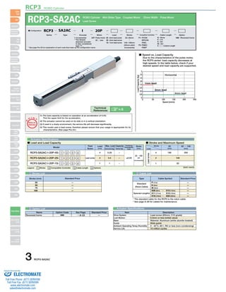
RCP3-SA2AC ROBO Cylinder Mini Slider Type Coupled Motor 22mm Width Pulse Motor
I: Incremental
* The Simple
absolute encoder
is also considered
type "I".
20P: Pulse motor
20 □ size
* See page Pre-35 for explanation of each code that make up the configuration name.
O I N
Stroke (mm) Standard Price
—
—
—
—
2
1.75
1.5
1.25
1.0
0.75
0.5
0.25
3 Cable List
Lead Screw
Feed
Screw
Technical
References A-5
Lead
(mm)
4
2
1
Max. Load Capacity Positioning
Horizontal (kg)
0.25
0.5
1
Vertical (kg)
Repeatability
(mm)
Model
−
−
−
±0.05
Stroke
(mm)
RCP3-SA2AC-I-20P-4S- 1 - 2 - 3 - 4
RCP3-SA2AC-I-20P-2S- 1 - 2 - 3 - 4
RCP3-SA2AC-I-20P-1S- 1 - 2 - 3 - 4
25~100
(25
increments)
Lead screw
■ Speed vs. Load Capacity
Due to the characteristics of the pulse motor,
the RCP3 series' load capacity decreases at
high speeds. In the table below, check if your
desired speed and load capacity are supported.
1mm lead
Horizontal
2mm lead
4mm lead
0 50 100 150 200 250
Speed (mm/s)
0
Load Capacity (kg)
Actuator Specifications
■ Lead and Load Capacity ■ Stroke and Maximum Speed
Stroke
Lead
25
(mm)
50 ~ 100
(mm)
180 200
100
50
4
2
1
(Unit: mm/s)
(1) The load capacity is based on operation at an acceleration of 0.2G.
This the upper limit for the acceleration.
(2) The actuator cannot be used on its side or in a vertical orientation.
(3) If used in a dusty environment, the service life will decrease significantly.
(4) This model uses a lead screw, therefore please ensure that your usage is appropriate for its
characteristics. (See page Pre-42.)
P
T
Notes on
Selection
Type Cable Symbol Standard Price
Standard
(Robot Cables)
* The standard cable for the RCP3 is the robot cable.
* See page A-39 for cables for maintenance.
1 Stroke List
Special Lengths
P (1m)
S (3m)
M (5m)
X06 (6m) ~ X10 (10m)
X11 (11m) ~ X15 (15m)
X16 (16m) ~ X20 (20m)
—
—
—
—
—
—
Actuator Specifications
Item Description
Lead screw (Ø4mm, C10 grade)
0.3mm or less (initial value)
Material: Aluminum (white alumite treated)
Slide guide
0~40°C, 85% RH or less (non-condensing)
10 million cycles
Drive System
Lost Motion
Base
Guide
Ambient Operating Temp./Humidity
Service Life
Legend 1 Stroke 2 Compatible Controller 3 Cable Length 4 Options
Lead screw
25
50
75
100
4 Option List
Name Option Code See Page Standard Price
Reversed-home NM → A-33 —
P1: PCON
RPCON
PSEL
P3: PMEC
PSEP
4S : 4mm lead screw
2S : 2mm lead screw
1S : 1mm lead screw
■ Configuration: RCP3 SA2AC I 20P
Series Type Encoder Motor Lead Stroke Compatible Controllers Cable Length Option
25: 25mm
〜
100: 100mm
(25mm pitch
increments)
N : None NM : Reversed-home
P : 1m
S : 3m
M : 5m
X □□ : Custom Length
3 RCP3-SA2AC
Slider
Type
Mini
Standard
Controllers
Integrated
Rod
Type
Mini
Standard
Controllers
Integrated
Table/Arm
/Flat Type
Mini
Standard
Gripper/
Rotary Type
Linear Servo
Type
Cleanroom
Type
Splash-Proof
Controllers
PMEC
/AMEC
PSEP
/ASEP
ROBO
NET
ERC2
PCON
ACON
SCON
PSEL
ASEL
SSEL
XSEL
Pulse Motor
Servo Motor
(24V)
Servo Motor
(200V)
Linear
Servo Motor
Sold & Serviced By:
ELECTROMATE
Toll Free Phone (877) SERVO98
Toll Free Fax (877) SERV099
www.electromate.com
sales@electromate.com
2. RCP3 ROBO Cylinder
(200)
Cable joint
connector*1
ST: Stroke
ME: Mechanical end
SE: Stroke end
*1: A motor-encoder cable is connected here. See page A-39 for details on cables.
*2: During the homing operation, the slider moves to actuator's mechanical end, and then reverses. Therefore, watch
4-M3 depth 5.5
17±0.02
8±0.02
2-ø2H7 depth 3
17±0.1
17±0.1
3
9
2
ME SE
ST
A
L
3
28 28
2
Home ME*2
73.5
24.5
1
D-M3 depth 4
2-ø3H7 depth 3
(from bottom of base)
B 15
C
Z
10
10
28
5 5
4
26
3H7 depth 3
(from bottom of base)
22
12.5
27
Details of Z
Secure at least 100
for any interference with its surroundings.
Dimensions
■ Dimensions/Weight by Stroke
Stroke
L
A
B
C
D
Weight (kg)
25 50 75 100
169.5
96
25
0
4
0.25
194.5
121
50
0
4
0.27
219.5
146
75
0
4
0.29
244.5
171
100
50
6
0.3
For Special Orders A-9
2 Compatible Controllers
The RCP3 series actuators can operate with the controllers below. Select the controller according to your usage.
Name External View Model Description Max. Positioning Points Input Voltage Power Supply Capacity Standard Price See Page
* This is for the single-axis PSEL.
* 1 is a placeholder for the power supply voltage (1: 100V / 2: 100~240V).
Solenoid Valve Type
PMEC-C-20PI-NP-2-1
Easy-to-use controller,
even for beginners
3 points
AC100V
AC200V
See P481 — → P477
PSEP-C-20PI-NP-2-0 Operable with same signal as
solenoid valve. Supports
both single and double
solenoid types.
No homing necessary with
simple absolute type.
DC24V 2A Max.
—
→ P487
Splash-Proof
Solenoid Valve Type
PSEP-CW-20PI-NP-2-0 —
Positioner Type PCON-C-20PI-NP-2-0
Positioning is possible for up
to 512 points
512 points
—
→ P525
Safety-Compliant
Positioner Type
PCON-CG-20PI-NP-2-0 —
Pulse Train Input Type
(Differential Line Driver)
PCON-PL-20PI-NP-2-0
Pulse train input type with
differential line driver support
(−)
—
Pulse Train Input Type
(Open Collector)
PCON-PO-20PI-NP-2-0
Pulse train input type with
open collector support
—
Serial
Communication Type
PCON-SE-20PI-N-0-0
Dedicated to serial
communication
64 points —
Field Network Type RPCON-20P Dedicated to field network 768 points — → P503
Program
Control Type
PSEL-C-1-20PI-NP-2-0
Programmed operation is
possible. Can operate up to 2 axes
1500 points — → P557
RCP3-SA2AC 4
Slider
Type
Mini
Standard
Controllers
Integrated
Rod
Type
Mini
Standard
Controllers
Integrated
Table/Arm
/Flat Type
Mini
Standard
Gripper/
Rotary Type
Linear Servo
Type
Cleanroom
Type
Splash-Proof
Controllers
PMEC
/AMEC
PSEP
/ASEP
ROBO
NET
ERC2
PCON
ACON
SCON
PSEL
ASEL
SSEL
XSEL
Pulse Motor
Servo Motor
(24V)
Servo Motor
(200V)
Linear
Servo Motor
Sold & Serviced By:
ELECTROMATE
Toll Free Phone (877) SERVO98
Toll Free Fax (877) SERV099
www.electromate.com
sales@electromate.com