High Profile Call Girls Nagpur Meera Call 7001035870 Meet With Nagpur Escorts
Bias compensation ppt
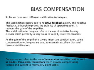
1. So far we have seen different stabilization techniques.
The stabilization occurs due to negative feedback action. The negative
feedback, although improves the stability of operating point, it
reduces the gain of the amplifier.
The stabilization techniques refer to the use of resistive biasing
circuits which permit IB to vary so as to keep IC relatively constant.
As the gain of the amplifier is a very important consideration, some
compensation techniques are used to maintain excellent bias and
thermal stabilization.
Compensation refers to the use of temperature sensitive devices such
as diodes, transistors, thermistors which provide compensating
voltage and current to maintain Q point stable.
3. These are the circuits that implement
compensation techniques using diodes to deal with
biasing instability.
There are two types of diode compensation
methods.
◦ Diode compensation for instability due to VBE variation
◦ Diode compensation for instability due to ICO variation
4. In a transistor, the changes in the value
of VBE results in the changes in IC .
A diode can be employed in the emitter
circuit in order to compensate the
variations in VBE or ICO.
As the diode and transistor used are of
same material, the voltage VD across the
diode has same temperature coefficient
as VBE of the transistor.
The diode D is forward biased by the
source VDD and the resistor RD. The
variation in VBE with temperature is
same as the variation in VD with
temperature, hence the quantity (VBE –
VD) remains constant.
So the current IC remains constant in
spite of the variation in VBE.
a) Diode in the Emitter Circuit
6. Diode is connected in series with resistance R2 in
the voltage divider circuit and it is forward
biased condition.
For voltage divider bias,
When VBE changes with temperature, IC also
changes
To cancel the changes in IC , one diode is used in
the circuit for compensation
The voltage at the base VB is give as
Substituting this value in equation IC, we get,
The changes in VBE. due to temperature are
compensated by changes in the diode voltage which
keeps IC stable at Q point.
b) Diode in the voltage divider circuit
7. In germanium transistor changes in ICO with
temperature plays an important role collector
current stability
* The diode is kept at reverse bias
condition ,so only leakage current flows
* Io increases then ICO also increases
As I is constant , IC also remains constant.
We can say that changes by ICO with temperature are compensated
by diode and collector current remains constant
8. Thermistor is a temperature sensitive element with
negative temperature coefficient
With increase of temperature ,RT decreases.
Hence the voltage drop across it also decreases.
That is VBE decreases which reduces IB .this will offset the increased collector
current with temperature.
The equation shows if there is increase in ICO and decrease in IB keeps
IC almost constant.
9. Here, thermistor is connected between emitter and Vcc to minimize
the increase in collector current due to changes in ICO, VBE, or beta
with temperature
IC increases with temperature and RT decreases with increase in
temperature. Therefore, current flowing through RE increases,
which increases the voltage drop across it. E - B junction is forward
biased. But due to increase in voltage drop across RE, emitter is
made more positive, which reduces the forward bias voltage VBE.
Hence, bias current reduces.
10. Fig. shows sensistor compensation R1 is replaced by sensistor RT in self bias
circuit.
Now, RT and R2 resistors of the potential divider.
As temperature increases, RT increases which decreases the current flowing
through it. Hence current through R2 decreases which reduces the voltages drop
across it. Voltage drop across R2 is the voltage between base and ground. So
VBE reduces which decreases IB. It means, when ICBO increases with increase in
temperature, IB reduces due to reduction in VBE, maintaining IC fairly constant.