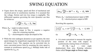
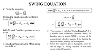
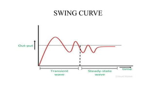
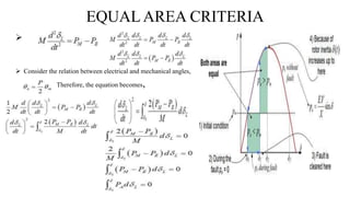
GANDHINAGAR INSTITUTE OF TECHNOLOGY
ELECTRICAL DEPARTMENT
 Interconnected Power System (2170901)
ALA Presentation on
 Topic: Swing Equation
Guided By: Prof. Piyush Pandya Prepared By: Darshil Shah (140120109050)
CONTENTS
 Introduction
 What is Power System Stability
 Stability Limit and Why Transient Stability limit is lower the Steady State
stability limit?
 Rotor Dynamics of Power System
 Swing Equation
 Swing Curves
 Equal Area Criteria
 Conclusion
 Reference
INTRODUCTION
 In the Power System Analysis, approaches says that the Power system
consists lots of devices interconnected to each other.
 Although Stability at every point must be common for all those devices.
 Here, each and every devices have them own protection from the transients.
 Stability of any system can easily be calculated from the generation or load
side also.
POWER SYSTEM STABILITY
 Power System is a very large complex network consisting of synchronous
generators, transformers, switch gears etc.
 Basically, if the fault is occurs in the system the synchronism may break and
it will affect the whole line from Generation to the Load side.
 So, the stability criteria is most important here for remove the fault
condition and make the suitable and appropriate operation for the all
machines and whole power system.
 Power System Stability is the ability of the power system to return to steady
state without losing synchronism.
 Usually Power System Stability is categorized into Steady State, Transient
and Dynamic Stability.
STABILITY LIMIT
 The Stability limit is the maximum power that can be transferred in a
network between source and load without loss of synchronism.
 The steady state limit is maximum power that can be transferred without
the system becoming unstable.
 The transient stability limit is the maximum power that can be transferred
without the system becoming unstable when sudden or large disturbance
occurs.
 If in increase in field current or adjustments in speed settings occurs
simultaneously with an increase of load from the use of automatic voltage
regulators & speed governmenors, the stability limit would be increased
significantly.
WHY TRANSIENT STABILITY IS LOWER
THAN STEADY STATE STABILITY?
 If the system experiences a shock by sudden and large power changes and
violent fluctuations of voltage occurs.
 Consequently machines or group of machines may go out of step. The
rapidly of the application of the large disturbances is responsible for the
loss of stability, otherwise it may be possible to maintain stability if the
same large load is applied gradually.
 Thus, the transient stability limit is lower than the steady state limit.
ROTOR DYNAMICS OF POWER SYSTEM
 A synchronous machine is a
rotating body, the laws of machines
of rotating bodies are also
applicable to it.
 Kinetic energy of the rotor at
synchronous machine is,
 J = rotor moment of inertia in kg-
m2
 𝜔
𝑠𝑚 = synchronous speed in rad
(mech)/sec
𝑲. 𝑬. =
𝟏
𝟐
𝑱𝝎 𝒔𝒎 𝟐 × 𝟏𝟎−𝟔
MJ
But, 𝝎 𝒔 = (
𝑷
𝟐
)𝝎 𝒔𝒎 = rotor speed in rad (elect)/sec
P = number of machine poles
 𝑲. 𝑬. =
𝟏
𝟐
( 𝑱𝝎 𝒔
𝟐
𝑷
𝟐 × 𝟏𝟎−𝟔
)𝝎 𝒔 MJ
=
𝟏
𝟐
𝑴𝝎 𝒔
where, 𝑴 = 𝑱
𝟐
𝑷
𝟐 × 𝟏𝟎−𝟔
= moment of inertia in MJ-
sec/elect rad.
 We shall define the inertia constant H such that,
𝑮𝑯 = 𝑲. 𝑬. =
𝟏
𝟐
𝑴𝝎 𝒔 MJ
It immediately follows that,
𝑴 =
𝟐𝑮𝑯
𝝎 𝒔
=
𝑮𝑯
𝝅𝒇
MJ-sec/elect rad.
SWING EQUATION
 Figure shows the torque, speed and flow of mechanical and
electrical power in synchronous machine. It is assumed that
the voltage, friction and iron loss torque is negligible. The
differential equation governing the rotor dynamics can then
be written as:
Where, 𝜃 𝑚 = angle in radian (mech)
𝑇 𝑚 = turbine torque in Nm; it acquires a negative
value for a motoring machine.
𝑇𝑒 = electromagnetic torque developed in Nm
 While the rotor undergoes dynamics as per equation, the rotor
speed changes by insignificant magnitude for the time period
of interest (1sec). This equation can be converted into its
more convenient power form by assuming the rotor speed to
constant at synchronous speed (𝜔𝑠𝑚). Multiply bothe side of
equation by 𝜔𝑠𝑚 so,
𝑱
𝒅 𝟐 𝜽 𝒎
𝒅𝒕 𝟐 = 𝑻 𝒎 − 𝑻 𝒆 Nm
𝑱𝝎 𝒔𝒎
𝒅 𝟐 𝜽 𝒎
𝒅𝒕 𝟐 × 𝟏𝟎−𝟔
= 𝑷 𝒎 − 𝑷 𝒆 MW
Where, 𝑃𝑚 = mechanical power input in MW
𝑃𝑒 = electrical power output in MW
Rewriting this equation,
𝐽
2
𝑃
2
𝜔𝑠 × 10−6 𝑑2 𝜃 𝑒
𝑑𝑡2 = 𝑃𝑚 − 𝑃𝑒 MW
Or 𝑴
𝒅 𝟐 𝜽 𝒆
𝒅𝒕 𝟐 = 𝑷 𝒎 − 𝑷 𝒆.
 It is more convenient to measure the angular
position of the rotor with respect to
synchronously rotating frame of reference.
𝜹 = 𝜽 𝒆 − 𝝎 𝒔 𝒕 ; rotor angle
displacement from sync. Rotating reference
frame called Torque angle or Power angle.
SWING EQUATION
 From the equation,
𝑑2 𝜃 𝑒
𝑑𝑡2 =
𝑑2 𝛿
𝑑𝑡2
Hence, the equation can be written in
terms of,
𝑴
𝒅 𝟐 𝜹
𝒅𝒕 𝟐 = 𝑷 𝒎 − 𝑷 𝒆 MW
With M as defined in equation, we can
write
𝑮𝑯
𝝅𝒇
𝒅 𝟐 𝜹
𝒅𝒕 𝟐 = 𝑷 𝒎 − 𝑷 𝒆 MW
 Dividing through G, the MVA rating
in machine,
𝑴 𝒑𝒖
𝒅 𝟐 𝜹
𝒅𝒕 𝟐 = 𝑷 𝒎 − 𝑷 𝒆 ; in pu of machine rating as base
𝑀 𝑝𝑢 =
𝐻
𝜋𝑓
or,
𝑯
𝝅𝒇
𝒅 𝟐 𝜹
𝒅𝒕 𝟐 = 𝑷 𝒎 − 𝑷 𝒆 pu
 This equation is called as “Swing Equation”. It is
a second order differential equation where the
damping term is absent 𝑑𝛿 𝑑𝑡 because of the
assumption of a lossless machine & the fact that the
torque of damper winding has been ignored.
 Since, the electrical power 𝑃𝑒 depends upon the
sine of angle 𝛿 . Swing equation is non-linear
second order diff. equation.
SWING CURVE
EQUAL AREA CRITERIA
 This is a simple graphical method to predict the transient of two machine
system or a single machine against infinite bus.
 This criterion does not required Swing Equation or solution or Swing
Equation to determine the stability condition.
 The stability condition are determined by equating the areas of segments
on Power angle diagram.
 The equation as follows:
 Consider the relationship between load angle and power derived from
Swing equation, 𝑴
𝒅 𝟐 𝜹 𝑳
𝒅𝒕 𝟐 = 𝑷 𝑨
 Here, Angular momentum is denoted as M, Load angle is denoted as δL,
and Actual power is denoted as PA.
EQUAL AREA CRITERIA

 Consider the relation between electrical and mechanical angles,
Therefore, the equation becomes,
CONCLUSION
 Hence, this equation is very helpful to determine the stability condition of
any complex power system through calculating the angle δ and also having
the equal area criteria. So, any kind of transients can be eliminated from this.
REFERENCE
 www.en.Wikipedia.org/Swing-Equation
 https://www.electrical4u.com/transient-stability-and-swing-equation
 www.circuitglobe.com/swing-equation
 Power Systems and Analysis by D P Kothari and I J Nagrath
Swing equation

Swing equation

  • 1.
    GANDHINAGAR INSTITUTE OFTECHNOLOGY ELECTRICAL DEPARTMENT  Interconnected Power System (2170901) ALA Presentation on  Topic: Swing Equation Guided By: Prof. Piyush Pandya Prepared By: Darshil Shah (140120109050)
  • 2.
    CONTENTS  Introduction  Whatis Power System Stability  Stability Limit and Why Transient Stability limit is lower the Steady State stability limit?  Rotor Dynamics of Power System  Swing Equation  Swing Curves  Equal Area Criteria  Conclusion  Reference
  • 3.
    INTRODUCTION  In thePower System Analysis, approaches says that the Power system consists lots of devices interconnected to each other.  Although Stability at every point must be common for all those devices.  Here, each and every devices have them own protection from the transients.  Stability of any system can easily be calculated from the generation or load side also.
  • 4.
    POWER SYSTEM STABILITY Power System is a very large complex network consisting of synchronous generators, transformers, switch gears etc.  Basically, if the fault is occurs in the system the synchronism may break and it will affect the whole line from Generation to the Load side.  So, the stability criteria is most important here for remove the fault condition and make the suitable and appropriate operation for the all machines and whole power system.  Power System Stability is the ability of the power system to return to steady state without losing synchronism.  Usually Power System Stability is categorized into Steady State, Transient and Dynamic Stability.
  • 5.
    STABILITY LIMIT  TheStability limit is the maximum power that can be transferred in a network between source and load without loss of synchronism.  The steady state limit is maximum power that can be transferred without the system becoming unstable.  The transient stability limit is the maximum power that can be transferred without the system becoming unstable when sudden or large disturbance occurs.  If in increase in field current or adjustments in speed settings occurs simultaneously with an increase of load from the use of automatic voltage regulators & speed governmenors, the stability limit would be increased significantly.
  • 6.
    WHY TRANSIENT STABILITYIS LOWER THAN STEADY STATE STABILITY?  If the system experiences a shock by sudden and large power changes and violent fluctuations of voltage occurs.  Consequently machines or group of machines may go out of step. The rapidly of the application of the large disturbances is responsible for the loss of stability, otherwise it may be possible to maintain stability if the same large load is applied gradually.  Thus, the transient stability limit is lower than the steady state limit.
  • 7.
    ROTOR DYNAMICS OFPOWER SYSTEM  A synchronous machine is a rotating body, the laws of machines of rotating bodies are also applicable to it.  Kinetic energy of the rotor at synchronous machine is,  J = rotor moment of inertia in kg- m2  𝜔 𝑠𝑚 = synchronous speed in rad (mech)/sec 𝑲. 𝑬. = 𝟏 𝟐 𝑱𝝎 𝒔𝒎 𝟐 × 𝟏𝟎−𝟔 MJ But, 𝝎 𝒔 = ( 𝑷 𝟐 )𝝎 𝒔𝒎 = rotor speed in rad (elect)/sec P = number of machine poles  𝑲. 𝑬. = 𝟏 𝟐 ( 𝑱𝝎 𝒔 𝟐 𝑷 𝟐 × 𝟏𝟎−𝟔 )𝝎 𝒔 MJ = 𝟏 𝟐 𝑴𝝎 𝒔 where, 𝑴 = 𝑱 𝟐 𝑷 𝟐 × 𝟏𝟎−𝟔 = moment of inertia in MJ- sec/elect rad.  We shall define the inertia constant H such that, 𝑮𝑯 = 𝑲. 𝑬. = 𝟏 𝟐 𝑴𝝎 𝒔 MJ It immediately follows that, 𝑴 = 𝟐𝑮𝑯 𝝎 𝒔 = 𝑮𝑯 𝝅𝒇 MJ-sec/elect rad.
  • 8.
    SWING EQUATION  Figureshows the torque, speed and flow of mechanical and electrical power in synchronous machine. It is assumed that the voltage, friction and iron loss torque is negligible. The differential equation governing the rotor dynamics can then be written as: Where, 𝜃 𝑚 = angle in radian (mech) 𝑇 𝑚 = turbine torque in Nm; it acquires a negative value for a motoring machine. 𝑇𝑒 = electromagnetic torque developed in Nm  While the rotor undergoes dynamics as per equation, the rotor speed changes by insignificant magnitude for the time period of interest (1sec). This equation can be converted into its more convenient power form by assuming the rotor speed to constant at synchronous speed (𝜔𝑠𝑚). Multiply bothe side of equation by 𝜔𝑠𝑚 so, 𝑱 𝒅 𝟐 𝜽 𝒎 𝒅𝒕 𝟐 = 𝑻 𝒎 − 𝑻 𝒆 Nm 𝑱𝝎 𝒔𝒎 𝒅 𝟐 𝜽 𝒎 𝒅𝒕 𝟐 × 𝟏𝟎−𝟔 = 𝑷 𝒎 − 𝑷 𝒆 MW Where, 𝑃𝑚 = mechanical power input in MW 𝑃𝑒 = electrical power output in MW Rewriting this equation, 𝐽 2 𝑃 2 𝜔𝑠 × 10−6 𝑑2 𝜃 𝑒 𝑑𝑡2 = 𝑃𝑚 − 𝑃𝑒 MW Or 𝑴 𝒅 𝟐 𝜽 𝒆 𝒅𝒕 𝟐 = 𝑷 𝒎 − 𝑷 𝒆.  It is more convenient to measure the angular position of the rotor with respect to synchronously rotating frame of reference. 𝜹 = 𝜽 𝒆 − 𝝎 𝒔 𝒕 ; rotor angle displacement from sync. Rotating reference frame called Torque angle or Power angle.
  • 9.
    SWING EQUATION  Fromthe equation, 𝑑2 𝜃 𝑒 𝑑𝑡2 = 𝑑2 𝛿 𝑑𝑡2 Hence, the equation can be written in terms of, 𝑴 𝒅 𝟐 𝜹 𝒅𝒕 𝟐 = 𝑷 𝒎 − 𝑷 𝒆 MW With M as defined in equation, we can write 𝑮𝑯 𝝅𝒇 𝒅 𝟐 𝜹 𝒅𝒕 𝟐 = 𝑷 𝒎 − 𝑷 𝒆 MW  Dividing through G, the MVA rating in machine, 𝑴 𝒑𝒖 𝒅 𝟐 𝜹 𝒅𝒕 𝟐 = 𝑷 𝒎 − 𝑷 𝒆 ; in pu of machine rating as base 𝑀 𝑝𝑢 = 𝐻 𝜋𝑓 or, 𝑯 𝝅𝒇 𝒅 𝟐 𝜹 𝒅𝒕 𝟐 = 𝑷 𝒎 − 𝑷 𝒆 pu  This equation is called as “Swing Equation”. It is a second order differential equation where the damping term is absent 𝑑𝛿 𝑑𝑡 because of the assumption of a lossless machine & the fact that the torque of damper winding has been ignored.  Since, the electrical power 𝑃𝑒 depends upon the sine of angle 𝛿 . Swing equation is non-linear second order diff. equation.
  • 10.
  • 11.
    EQUAL AREA CRITERIA This is a simple graphical method to predict the transient of two machine system or a single machine against infinite bus.  This criterion does not required Swing Equation or solution or Swing Equation to determine the stability condition.  The stability condition are determined by equating the areas of segments on Power angle diagram.  The equation as follows:  Consider the relationship between load angle and power derived from Swing equation, 𝑴 𝒅 𝟐 𝜹 𝑳 𝒅𝒕 𝟐 = 𝑷 𝑨  Here, Angular momentum is denoted as M, Load angle is denoted as δL, and Actual power is denoted as PA.
  • 12.
    EQUAL AREA CRITERIA  Consider the relation between electrical and mechanical angles, Therefore, the equation becomes,
  • 13.
    CONCLUSION  Hence, thisequation is very helpful to determine the stability condition of any complex power system through calculating the angle δ and also having the equal area criteria. So, any kind of transients can be eliminated from this.
  • 14.
    REFERENCE  www.en.Wikipedia.org/Swing-Equation  https://www.electrical4u.com/transient-stability-and-swing-equation www.circuitglobe.com/swing-equation  Power Systems and Analysis by D P Kothari and I J Nagrath