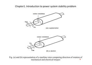
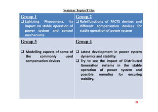
Power System Dynamics and Stability
Ch. 1-Introduction:
Synchronous Machines Rotor Dynamics
Swing Equation
Power Flow /Transfer and Rotor angle
by
Dr.Wondwossen Astatike Haile
BSc (BEET), MSc (Power Engineering), PhD (Electrical and Electronics Engineering)
Department of Electrical Power Engineering
College of Engineering, Defense University
1
Chapter1. Introduction to power system stability problem
 Power system dynamics is also called power system stability problem.
 Modern power systems are very widely interconnected.
 Interconnection results in operating economy, increased reliability, and
mutual assistance of different systems.
 In the meantime, interconnection will also contribute to the stability problem.
 Due to this stability problem become an important concern for power system
engineers in an interconnected system.
 Methodology for power system stability problem analysis are modelling of the
system, and once the mathematical model of a power system is developed, one is
to obtain the solution through numerical techniques.
 Development of mathematical model of power system includes mathematical
model for synchronous machines, excitation systems, voltage regulator, governor
and loads.
 Power system stability may be defined as that property of a power system that
enables it to remain in state of operating equilibrium under normal
condition and to regain an acceptable state of equilibrium after being
subjected to a disturbance. That is,
 Ability to remain in operating equilibrium
 Equilibrium between opposing forces 2
Chapter1. Introduction to power system stability problem
 Classification of power system stability are:
1. Angle stability
2. Voltage stability
1. Angle stability: further classified in to
 Small signal stability
 Transient stability
 Mid-term stability
 Long -term stability
2. Voltage stability: also classified in to
 Large disturbance voltage stability
 Small disturbance voltage stability
3
Chapter1. Introduction to power system stability problem
 Rotor angle stability
 It is the ability of interconnected synchronous machines of a power system
to remain in synchronism. i.e. ability to maintain synchronism and torque
balance of synchronous machines.
 To analyse power system stability we have to understand the dynamics of the
rotor and develop a mathematical equations to describe the dynamics of the
rotor.
Synchronous Machines Rotor dynamics and the swing equation
 The equation governing the motion of the rotor of a synchronous machine is
based on the elementary principle in dynamics.
 It states that an accelerating torque is the product of the moment of inertia and
angular acceleration.
 This is a fundamental law on which the swing equation is based on.
 A synchronous machine may operate either as a synchronous generator or as a
synchronous motor.
4
Chapter1. Introduction to power system stability problem
Fig. (a) and (b) representation of a machine rotor comparing direction of rotation of
mechanical and electrical torques 5
Chapter1. Introduction to power system stability problem
Where,
 Tm and Te operate on the rotor in opposite direction
 The mechanical torque, Tm is provided by the prime mover
 The electrical torque, Te is developed by the interaction of magnetic field and
stator currents.
From the above diagrams,
 The rotor rotates in the direction of the mechanical torque in the case of
generator and in the direction of electrical torque in the case of motor.
 Under steady operating condition these two torques are equal and the rotor of the
synchronous machine rotates with synchronous speed.
 However, when disturbances occur there exists unequilibrium between the
two torques and the two torques are not equal and the difference is called
accelerating torque
6
Chapter1. Introduction to power system stability problem
The swing equation
 A differential equation can be written relating the accelerating torque, moment of
inertia and acceleration. That is,
• In mks system of units,
• J= the total moment of inertia in Kg-m2
• m= angular displacement of rotor with respect to a stationary axis in mechanical
radians
• t=time in seconds
• Tm= mechanical or shaft torque supplied by prime mover less retarding torque
due to rotational losses in N-m
• Te= the net electrical torque or electromagnetic torque in N-m
• Ta= the net accelerating torque in N-m
 It is convenient to measure the rotor angular position with respect to reference
axis which rotates at synchronous speed. Therefore, we define,
7
Chapter1. Introduction to power system stability problem
(2)
• sm= synchronous speed of the machine in mechanical radians/sec
• m= the angular displacement of rotor in mechanical radians from the
synchronously rotating reference axis.
 The derivatives of eq.2 with respect to time are
(3)
 And taking the second derivatives of eq.3 gives us,
(4)
 Substituting eq.4 into eq.1, we obtain,
(5)
8
Chapter1. Introduction to power system stability problem
 In power system studies we are more comfortable with the terms in power like
watts, kilowatts and megawatts.
 In this regard multiplying eq.5 by m which is denoted by eq.6 yields eq.7,
(6)
(7)
• Where,
• mTm=Pm
• mTe=Pe
• Pm= shaft power input to the machine less rotational losses
• Pe= the electrical power crossing the air gap
 Eq.7 may be written as
9
Chapter1. Introduction to power system stability problem
(8)
• Where,
• J= moment of inertia in Kg/m2
• m= speed in rad/s
• Jm= is called angular momentum
 In practical condition, the rotor speed m is nearly equal to the synchronous speed.
The difference become large only when the machine losses synchronism.
 For the purpose of simplicity m= sm. Then, the coefficient Jm is the angular
momentum of the rotor, at synchronous speed sm it is denoted by M and it is
called inertia constant of the machine.
(9)
• Where, M=Jm
 The M term varies over a wide range depending on the type of machine. That is
whether a synchronous generator or turbo generator. In that case it demands to
define another Inertia constant, H as follows:
10
Chapter1. Introduction to power system stability problem
Inertia constant, H
 H is defined by
{MJ/MVA} (10)
Where,
• Smach= the three phase rating of the machine in MVA
 Solving for M, from equation 10 , we get,
11
Chapter1. Introduction to power system stability problem
(11)
 Substituting for M in eq.9, we find
(12)
OR
(13)
Where,
−
−
 The per unit system of calculation is very convenient in power system analysis.
Generally, Pm(pu) &Pe(pu) are represented as Pm &Pe only for simplicity.
12
Chapter1. Introduction to power system stability problem
 So that Eq.13 becomes,
(14)
 Finally, eq.14 is rewritten as,
(15)
 Eq.15 is called the swing equation for synchronous machine.
 It is applicable both for generator and motor.
 The only difference is in case of motor Pm become negative and Pe
become negative and the equation become
(16)
 For a system with an electrical frequency f Hz, eq.15 is rewritten as
13
Chapter1. Introduction to power system stability problem
(17)
Where,
•  is in electrical radians
 For  in electrical degrees eq.17 will be rewritten as
(18)
 The swing equation is called second order non-linear differential equation.
 The solution of the swing equation is called a swing curve.
 In analysis, the solution of the second order differential equation can be
obtained by writing it in to two first order differential equations represented by
the following two equations in (19)&(20):
14
Chapter1. Introduction to power system stability problem
(19)
(20)
 When the swing equation is solved we obtain the expression for  as a function
of time.
 The graph of the solution is called swing curve of the machine and inspection of
the swing curves of all the machines of the system will show whether the
machines remain in synchronism after a disturbance or not.
 In a multi machine system, the output and hence the accelerating power of each
machine depend upon the angular position –and, to be more rigorous, also up on
the angular speeds- of all the machine of the system.
 Thus, for a 3-machine system there are three simultaneous differential equations.
That is,
(21)
15
Chapter1. Introduction to power system stability problem
(22)
(23)
 The system considered in equations 21 to 23 is in dynamic condition.
 When the system rotor is in dynamic condition, it develops some damping
torque.
 The damping torque is proportional to the speed deviation with respect to the
synchronously rotating field.
 To simplify the analysis, usually the damping torque is ignored and the final
equations will take the following final forms:
(24)
(25)
16
Chapter1. Introduction to power system stability problem
(26)
Power versus angle relationships
 An important characteristic of power system stability is the relationship between
interchange power and positions of rotors of synchronous machines.
 This relationship is highly nonlinear.
17
This image cannot currently be displayed.
Chapter1. Introduction to power system stability problem
18
Chapter1. Introduction to power system stability problem
 If we plot power angle  and power P or electrical power Pe it looks like:
Fig. power versus angle curve
(27)
19
Chapter1. Introduction to power system stability problem
 On same power angle curve diagram of figure above, if we draw the
mechanical input line, the mechanical input is not function of .
Therefore, it comes out to be a line parallel to  line/axis.
 For the system operating at point “a” and if it is perturb, then it
develop the forces and return back to the operating point “a”.
 However, if the system is made to operate at point “b”, which is also
an equilibrium point, and perturb, the system will lose its stability.
It will not develop restoring forces to return it back to point “b”.
20
Seminar Topics/Titles
21
Group 1
 Lightning Phenomena, its
impact on stable operation of
power system and control
mechanisms
Group 2
 Role/functions of FACTS devices and
different compensation devices for
stable operation of power system
Group 3
 Modelling aspects of some of
the commonly used
compensation devices
Group 4
 Latest development in power system
dynamics and stability.
 Try to see the impact of Distributed
Generation systems in the stable
operation of power system and
possible remedies for ensuring
stability.
END OF
Ch. 1- Introduction to power system stability
problem

Thank you
22

POWER SYSTEM DYNAMICS AND STABLITY CHAP1

  • 1.
    Power System Dynamicsand Stability Ch. 1-Introduction: Synchronous Machines Rotor Dynamics Swing Equation Power Flow /Transfer and Rotor angle by Dr.Wondwossen Astatike Haile BSc (BEET), MSc (Power Engineering), PhD (Electrical and Electronics Engineering) Department of Electrical Power Engineering College of Engineering, Defense University 1
  • 2.
    Chapter1. Introduction topower system stability problem  Power system dynamics is also called power system stability problem.  Modern power systems are very widely interconnected.  Interconnection results in operating economy, increased reliability, and mutual assistance of different systems.  In the meantime, interconnection will also contribute to the stability problem.  Due to this stability problem become an important concern for power system engineers in an interconnected system.  Methodology for power system stability problem analysis are modelling of the system, and once the mathematical model of a power system is developed, one is to obtain the solution through numerical techniques.  Development of mathematical model of power system includes mathematical model for synchronous machines, excitation systems, voltage regulator, governor and loads.  Power system stability may be defined as that property of a power system that enables it to remain in state of operating equilibrium under normal condition and to regain an acceptable state of equilibrium after being subjected to a disturbance. That is,  Ability to remain in operating equilibrium  Equilibrium between opposing forces 2
  • 3.
    Chapter1. Introduction topower system stability problem  Classification of power system stability are: 1. Angle stability 2. Voltage stability 1. Angle stability: further classified in to  Small signal stability  Transient stability  Mid-term stability  Long -term stability 2. Voltage stability: also classified in to  Large disturbance voltage stability  Small disturbance voltage stability 3
  • 4.
    Chapter1. Introduction topower system stability problem  Rotor angle stability  It is the ability of interconnected synchronous machines of a power system to remain in synchronism. i.e. ability to maintain synchronism and torque balance of synchronous machines.  To analyse power system stability we have to understand the dynamics of the rotor and develop a mathematical equations to describe the dynamics of the rotor. Synchronous Machines Rotor dynamics and the swing equation  The equation governing the motion of the rotor of a synchronous machine is based on the elementary principle in dynamics.  It states that an accelerating torque is the product of the moment of inertia and angular acceleration.  This is a fundamental law on which the swing equation is based on.  A synchronous machine may operate either as a synchronous generator or as a synchronous motor. 4
  • 5.
    Chapter1. Introduction topower system stability problem Fig. (a) and (b) representation of a machine rotor comparing direction of rotation of mechanical and electrical torques 5
  • 6.
    Chapter1. Introduction topower system stability problem Where,  Tm and Te operate on the rotor in opposite direction  The mechanical torque, Tm is provided by the prime mover  The electrical torque, Te is developed by the interaction of magnetic field and stator currents. From the above diagrams,  The rotor rotates in the direction of the mechanical torque in the case of generator and in the direction of electrical torque in the case of motor.  Under steady operating condition these two torques are equal and the rotor of the synchronous machine rotates with synchronous speed.  However, when disturbances occur there exists unequilibrium between the two torques and the two torques are not equal and the difference is called accelerating torque 6
  • 7.
    Chapter1. Introduction topower system stability problem The swing equation  A differential equation can be written relating the accelerating torque, moment of inertia and acceleration. That is, • In mks system of units, • J= the total moment of inertia in Kg-m2 • m= angular displacement of rotor with respect to a stationary axis in mechanical radians • t=time in seconds • Tm= mechanical or shaft torque supplied by prime mover less retarding torque due to rotational losses in N-m • Te= the net electrical torque or electromagnetic torque in N-m • Ta= the net accelerating torque in N-m  It is convenient to measure the rotor angular position with respect to reference axis which rotates at synchronous speed. Therefore, we define, 7
  • 8.
    Chapter1. Introduction topower system stability problem (2) • sm= synchronous speed of the machine in mechanical radians/sec • m= the angular displacement of rotor in mechanical radians from the synchronously rotating reference axis.  The derivatives of eq.2 with respect to time are (3)  And taking the second derivatives of eq.3 gives us, (4)  Substituting eq.4 into eq.1, we obtain, (5) 8
  • 9.
    Chapter1. Introduction topower system stability problem  In power system studies we are more comfortable with the terms in power like watts, kilowatts and megawatts.  In this regard multiplying eq.5 by m which is denoted by eq.6 yields eq.7, (6) (7) • Where, • mTm=Pm • mTe=Pe • Pm= shaft power input to the machine less rotational losses • Pe= the electrical power crossing the air gap  Eq.7 may be written as 9
  • 10.
    Chapter1. Introduction topower system stability problem (8) • Where, • J= moment of inertia in Kg/m2 • m= speed in rad/s • Jm= is called angular momentum  In practical condition, the rotor speed m is nearly equal to the synchronous speed. The difference become large only when the machine losses synchronism.  For the purpose of simplicity m= sm. Then, the coefficient Jm is the angular momentum of the rotor, at synchronous speed sm it is denoted by M and it is called inertia constant of the machine. (9) • Where, M=Jm  The M term varies over a wide range depending on the type of machine. That is whether a synchronous generator or turbo generator. In that case it demands to define another Inertia constant, H as follows: 10
  • 11.
    Chapter1. Introduction topower system stability problem Inertia constant, H  H is defined by {MJ/MVA} (10) Where, • Smach= the three phase rating of the machine in MVA  Solving for M, from equation 10 , we get, 11
  • 12.
    Chapter1. Introduction topower system stability problem (11)  Substituting for M in eq.9, we find (12) OR (13) Where, − −  The per unit system of calculation is very convenient in power system analysis. Generally, Pm(pu) &Pe(pu) are represented as Pm &Pe only for simplicity. 12
  • 13.
    Chapter1. Introduction topower system stability problem  So that Eq.13 becomes, (14)  Finally, eq.14 is rewritten as, (15)  Eq.15 is called the swing equation for synchronous machine.  It is applicable both for generator and motor.  The only difference is in case of motor Pm become negative and Pe become negative and the equation become (16)  For a system with an electrical frequency f Hz, eq.15 is rewritten as 13
  • 14.
    Chapter1. Introduction topower system stability problem (17) Where, •  is in electrical radians  For  in electrical degrees eq.17 will be rewritten as (18)  The swing equation is called second order non-linear differential equation.  The solution of the swing equation is called a swing curve.  In analysis, the solution of the second order differential equation can be obtained by writing it in to two first order differential equations represented by the following two equations in (19)&(20): 14
  • 15.
    Chapter1. Introduction topower system stability problem (19) (20)  When the swing equation is solved we obtain the expression for  as a function of time.  The graph of the solution is called swing curve of the machine and inspection of the swing curves of all the machines of the system will show whether the machines remain in synchronism after a disturbance or not.  In a multi machine system, the output and hence the accelerating power of each machine depend upon the angular position –and, to be more rigorous, also up on the angular speeds- of all the machine of the system.  Thus, for a 3-machine system there are three simultaneous differential equations. That is, (21) 15
  • 16.
    Chapter1. Introduction topower system stability problem (22) (23)  The system considered in equations 21 to 23 is in dynamic condition.  When the system rotor is in dynamic condition, it develops some damping torque.  The damping torque is proportional to the speed deviation with respect to the synchronously rotating field.  To simplify the analysis, usually the damping torque is ignored and the final equations will take the following final forms: (24) (25) 16
  • 17.
    Chapter1. Introduction topower system stability problem (26) Power versus angle relationships  An important characteristic of power system stability is the relationship between interchange power and positions of rotors of synchronous machines.  This relationship is highly nonlinear. 17 This image cannot currently be displayed.
  • 18.
    Chapter1. Introduction topower system stability problem 18
  • 19.
    Chapter1. Introduction topower system stability problem  If we plot power angle  and power P or electrical power Pe it looks like: Fig. power versus angle curve (27) 19
  • 20.
    Chapter1. Introduction topower system stability problem  On same power angle curve diagram of figure above, if we draw the mechanical input line, the mechanical input is not function of . Therefore, it comes out to be a line parallel to  line/axis.  For the system operating at point “a” and if it is perturb, then it develop the forces and return back to the operating point “a”.  However, if the system is made to operate at point “b”, which is also an equilibrium point, and perturb, the system will lose its stability. It will not develop restoring forces to return it back to point “b”. 20
  • 21.
    Seminar Topics/Titles 21 Group 1 Lightning Phenomena, its impact on stable operation of power system and control mechanisms Group 2  Role/functions of FACTS devices and different compensation devices for stable operation of power system Group 3  Modelling aspects of some of the commonly used compensation devices Group 4  Latest development in power system dynamics and stability.  Try to see the impact of Distributed Generation systems in the stable operation of power system and possible remedies for ensuring stability.
  • 22.
    END OF Ch. 1-Introduction to power system stability problem  Thank you 22