Systems & Software, Etc - Laser Focus World Article
•
0 likes•93 views

A very early article which includes all of the software that Dana Lee Church wrote while working for Systems & Software, Etc for Potomac Photonics, Inc. The article is a generalized article on the state of the art in laser micromachining but the true point was the addition of the automation via the software development. A very good article for the late '90's.

Recommended
More Related Content
What's hot
What's hot (15)
Similar to Systems & Software, Etc - Laser Focus World Article
Similar to Systems & Software, Etc - Laser Focus World Article (20)
More from Dana Lee Church
Recently uploaded
Recently uploaded (20)
Systems & Software, Etc - Laser Focus World Article
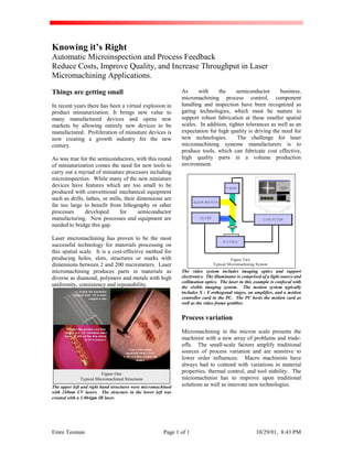
- 1. Emre Teoman Page 1 of 1 10/29/01, 8:43 PM Knowing it’s Right Automatic Microinspection and Process Feedback Reduce Costs, Improve Quality, and Increase Throughput in Laser Micromachining Applications. Things are getting small In recent years there has been a virtual explosion in product miniaturization. It brings new value to many manufactured devices and opens new markets by allowing entirely new devices to be manufactured. Proliferation of miniature devices is now creating a growth industry for the new century. As was true for the semiconductors, with this round of miniaturization comes the need for new tools to carry out a myriad of miniature processes including microinspection. While many of the new miniature devices have features which are too small to be produced with conventional mechanical equipment such as drills, lathes, or mills, their dimensions are far too large to benefit from lithography or other processes developed for semiconductor manufacturing. New processes and equipment are needed to bridge this gap. Laser micromachining has proven to be the most successful technology for materials processing on this spatial scale. It is a cost-effective method for producing holes, slots, structures or marks with dimensions between 2 and 200 micrometers. Laser micromachining produces parts in materials as diverse as diamond, polymers and metals with high uniformity, consistency and repeatability. Figure One Typical Micromachined Structures Com b structures approxim ately 1 m m w ide cutfrom polyim ide sheet. Polyim ide insulation stripped from 50 m icron copperw ires Stentlike pattern cutfrom solid 1 m m O D stainless steel tube. W idth ofthe thin struts is 50 m icrons.1 The upper left and right hand structures were micromachined with 248nm UV lasers. The structure in the lower left was created with a 1.064µµµµm IR laser. As with the semiconductor business, micromachining process control, component handling and inspection have been recognized as gating technologies, which must be mature to support robust fabrication at these smaller spatial scales. In addition, tighter tolerances as well as an expectation for high quality is driving the need for new technologies. The challenge for laser micromachining systems manufacturers is to produce tools, which can fabricate cost effective, high quality parts in a volume production environment. Figure Two Typical Micromachining System MOTIONM O TIO N CO M PUTERLA SER ILLUM INA TO R VIDEO The video system includes imaging optics and support electronics. The illuminator is comprised of a light source and collimation optics. The laser in this example is confocal with the visible imaging system. The motion system typically includes X - Y orthogonal stages, an amplifier, and a motion controller card in the PC. The PC hosts the motion card as well as the video frame grabber. Process variation Micromachining in the micron scale presents the machinist with a new array of problems and trade- offs. The small-scale factors amplify traditional sources of process variation and are sensitive to lower order influences. Macro machinists have always had to contend with variations in material properties, thermal control, and tool stability. The micromachinist has to improve upon traditional solutions as well as innovate new technologies.
- 2. Emre Teoman Page 2 of 2 10/29/01, 8:43 PM Table One Typical Error Budget Typical MicromachinistErrorBudget. Budget Comment Motion System Accuracy. +/-1 µm/in 8 µm 8" Stages Stage Orthogonality. <10 arcsec 5 µm Laser Beam Drift. 0.5 mRad 2 µm Withsystemdemag Structural variation 10 x 10-6 in/in /°F 2 µm +/- 10°F roomtemp (vibration/thermal). Material variation. 3 µm Application Specific PartsHandling inaccuracies. 2 µm Human Error. 2 pixel 3 µm Fiducial Capture Total Worst Case ProcessVariaiton 25 µµµµm Total Variation With Passive Compensation 10 µµµµm (Calibration & control) Total Variation with Active Compensation 4 µµµµm (Autoinspection) Typical Spec The spreadsheet above is an example of how a micromachinist might account for positioning variations. Material variation can include distortions due to mechanical loading, as well as the influence of humidity, and temperature. Human error includes, in this example, inaccuracies in manually acquiring fiducials on a video display. Passive compensation can include error mapping of x - y stages, and structural supports. Active compensation involves automated inspection with a machine vision system. Process variation in the micron world can come from numerous sources. Micro positioning motion systems often have difficulty maintaining peak performance over time. Linear inaccuracy, orthogonality deviations, and loading asymmetries all contribute to positioning errors. Structural supports also help to generate process variations. Vibration and thermal expansion conspire to reduce a micromachining system’s true accuracy. In addition, parts' handling in the micron world can be difficult and is significant source for process variation. Manipulating and machining micron size devices requires a whole new set of ‘jigs’ and fixtures to ensure high precision and control. Often underestimated are the instabilities of the laser- cutting tools. Beam pointing drift, mode quality shifts, and power variations can greatly influence the final product and are often difficult to monitor in production. Finally, one often-overlooked source of process variation is the human operator. Modern production systems require the human participant to maintain a high level of cognitive decision making capabilities, frequently in a repetitive manner. The man in the loop guarantees that there will be a yield associated with the process. All of these influences expand the error budget. Passive and active compensation techniques, like automated inspection, are needed to mitigate the effect of these variations. One axiom of production holds that the cost of rework increases by a factor of 10 for every step in production past the point of origin that a defect goes undetected. The case for in-process inspection is further bolstered given the relative difficulty in inspecting micro devices after processing. Traditional quality control methods are difficult to implement given small feature sizes. Inspecting the quality into the product after the fact is not cost effective. Human beings were not designed to build and inspect micron size devices and we require extensive technological support to do so effectively. Given the cost of rework, difficulty with postproduction inspection, and myriad sources for process variation in the micro scale, the need for smart tools with automatic real time microinspection and process feedback is acute. It is tough to get it right when things are small. The Nintendo Effect The revolution in computing over the last two decades is making it possible for systems designers to incorporate real time decision making capabilities into their video acquisition systems. Computer equipment manufacturers and software developers are spending millions of dollars in research and development to improve image processing and display technologies. The demand for faster and more complex games, humanistic interactive applications, real time video displays, and sophisticated video editing capabilities has created an opportunity for the micromachinist. Machine vision systems that only a few years ago cost tens of thousands of dollars and required racks of dedicated processing hardware can now be hosted on a common off the shelf PC. What was once a complex, expensive, video acquisition system is now a low cost, high speed PC frame- grabber, which can easily be installed into nearly any modern personal computer. Automated Microinspection and Closed Loop Feedback In its simplest form an automatic microinspection system includes an optical microscope, a video acquisition system, an image processor, and a user interface. The latter elements are often referred to as a machine vision system. The essential idea is to first acquire a digital image of the field of interest. After ‘grabbing’ the image the computer is then asked to extract and identify specific features. The position or scale of these features is evaluated and a decision is made. There are three basic actions, which can arise after the image has been processed:
- 3. Emre Teoman Page 3 of 3 10/29/01, 8:43 PM 1. A QC evaluation of whether the part is within specification (with subsequent sorting process) 2. An adjustment can be made to the motion control parameters (compensate for process variation like stage inaccuracy). 3. The part can be actively reworked (actively modify cut program to produce a better result). Common to all approaches, however, is an active closed loop feedback between the microinspection results and the process controller. At Potomac we have integrated our own motion control interpreter and machine vision system into a single application to provide a convenient interface for the micromachinist. This approach relieves the user from having to master complex software programming languages like Visual C++. Figure Three Machine Vision Software Tuning Application Machine Vision ToolsMachine Vision Tools The green boxes in the center of the image are machine vision regions of interest. The red lines are edge detection results. This application is used to generate motion control commands (Left hand side text box) which can then be integrated into a motion program. Most automated inspection applications start with a ‘tuning’ procedure. This sequence is required by the machine vision application to teach or train the software on the regions or features of interest. Figure three details a typical machine vision tuning application. In this case the tuning application provides the user with a convenient interface with which to manipulate live images, apply various feature extraction tools, and generate motion control commands which then can be integrated into the final control program. The tuning application can also be used to select the appropriate image processing algorithms. Contrast enhancement, pixel thresholding, dilation, and contour enhancements are some of the standard techniques used to improve the image quality and ensure robust feature extraction. Machine vision systems are only as good as the video microscope that they are mated to. The user must still provide the best possible image for the system in order to ensure consistent performance. Much has been written about the subject of video microscopy, there are, however, some basic elements to consider in order to obtain good image quality: • Select an appropriate field of view (FOV). The field should be big enough to easily contain the features of interest plus any process variation. • Select a resolution. Choose an appropriate combination of video resolution and optical demagnification to obtain a ‘micron per pixel’ value which is smaller than the smallest resolvable feature of interest. Larger (1/2” CCD cameras often help increase resolution) • Establish a working distance. This is the position of the part with respect to the objective. Longer working distances are often desirable. • Depth of Field. In the micro world features are rarely in the optimum optical plane. A generous depth of field will ensure good image quality over a range measurement positions. • Optimize the illumination. This is a science unto itself. Lighting is crucial to obtaining the best possible image contrast. Effort spent at on optimizing the illumination will often pay off in the form of better machine vision performance. There are a number of hardware features, which also should be considered. Good quality optics, adjusted for chromatic distortion, are needed to obtain the best possible contrast. High speed, large format (1/2” CCD) cameras are required for good image accuracy. Black and white cameras often provide good feature discrimination with a lower image-processing requirement. A high speed, machine vision specific, frame-grabber with PCI bus mastering is essential for quick and reliable image acquisition. Finally, a high clock rate computer with generous memory, a large cache, and high-speed bus rounds out the hardware needs.
- 4. Emre Teoman Page 4 of 4 10/29/01, 8:43 PM Figure Four Optical Setup Working Distance Lens Resolution Field of View Depth of Field Lighting Field of view, working distance, depth of field, resolution, and lighting are some of the critical optical parameters which must be considered to produce a successful machine vision image Figure Five Microinspection and Motion Control Software In this example the live video with active machine vision tools is on the upper left. Motion controls and feedback is positioned on the lower left. The upper right display covers the automated inspection results as well as the system status. The lower right is the motion program interface. Application One of the most common applications for machine vision systems is with the acquisition of alignment marks, or fiducials. Printed circuit board manufacturers have struggled for years with the precision alignment of unstable materials. By utilizing automated inspection technology to acquire the fiducials one can compensate for translation errors, fixture rotation as well as material deformation. Anything that can be brought into the field of view can conceivably be used as a reference. In one specific example a medical device manufacturer was applying its sensor to a glass plate. The difficulty lay in the inconsistent sensor application process. The sensor needed to be cut to within six microns. Process variations conspired to cause more than 25 µm of positioning error. Initially, the manual acquisition of fiducials and plate sorting were used to compensate for the variations. Automated inspection and machine vision was employed to improve throughput and quality. The end result was an automated process that significantly increased consistency, reduced the overall processing time by 20% and facilitated higher production capacity, all without significant modification of the micromachining equipment. In fact, the automated inspection system had a 95% success rate with sensor plates that were produced outside of the specified tolerances. The Bottom Line As predicted by futurists and science fiction writers, robotics and machine intelligence is beginning to integrate into society through its’ consumer products. The form of this integration is not, however, just automatons serving coffee. A hidden revolution is in industrial micro applications and the smart tools needed to serve them. Given the unrelenting march toward miniaturization, automated inspection and machine vision will be an essential technology for the cost effective, high volume, quality micro fabricator.