SlideShare a Scribd company logo
1 of 101
Download to read offline
TeoSys Proprietary - All Rights Reserved 2007 - 2013
2138 Priest Bridge Ct, Ste 10 Crofton MD, 21114 USA
www.TeoSys.com
LMS-5000 Custom Metal Parts Hole
Drilling System
LMS 5000
System Manual
Emre Teoman
Dana Lee Church
2007 / 2010
TeoSys Proprietary - All Rights Reserved 2007 - 2013
Series 5000 Laser Micromachining System System Manual Rev. E
Page 2 of 101
Table of Contents
TABLE OF CONTENTS................................................................................................................................. 2 
SAFETY............................................................................................................................................................ 5 
HAZARDS ........................................................................................................................................................ 6 
PROTECTIVE EYEWEAR ................................................................................................................................... 6 
SAFETY INTERLOCKS....................................................................................................................................... 6 
FACILITIES..................................................................................................................................................... 8 
PHYSICAL ENVELOPE............................................................................................................................... 8 
FRONT VIEW ............................................................................................................................................ 8 
TOP VIEW.................................................................................................................................................. 9 
SIDE VIEW ................................................................................................................................................ 9 
SYSTEM POWER REQUIREMENTS ....................................................................................................... 10 
REAR PANEL CONNECTIONS, COMPRESSED AIR AND VENTILATION........................................ 10 
SYSTEM REAR PANEL ........................................................................................................................... 10 
DIAGNOSIC SIGNALS.............................................................................................................................. 12 
Q-SWITCH............................................................................................................................................... 12 
FPS........................................................................................................................................................... 12 
LD Current............................................................................................................................................... 12 
EXTERNAL LASER CONNECTIONS ...................................................................................................... 13 
External System Control .......................................................................................................................... 13 
External Power Control........................................................................................................................... 13 
VACUUM CONNECTIONS....................................................................................................................... 13 
Debris Vent (Low Vacuum)...................................................................................................................... 13 
High Vacuum............................................................................................................................................ 13 
COMPRESSED AIR CONNECTION......................................................................................................... 13 
VENTILATION........................................................................................................................................... 14 
SYSTEM ENVRONMENTAL.................................................................................................................... 14 
SERVICE ACCESS ..................................................................................................................................... 15 
UNPACKING THE SYSTEM.............................................................................................................................. 16 
MAJOR SYSTEM COMPONENTS............................................................................................................ 17 
SYSTEM POWER UP................................................................................................................................... 18 
GENERAL SYSTEM OPERATION ........................................................................................................... 28 
ALTERNATE KEYENCE BASED DISCRIMINATOR........................................................................... 32 
SYSTEM SHUTDOWN ................................................................................................................................ 33 
LMS-5000 SUBSYSTEMS OPERATIONS, MAINTENANCE AND TROUBLESHOOTING............ 38 
GENERAL SYSTEM DESCRIPTION................................................................................................................... 38 
BASIC OPERATING SEQUENCE....................................................................................................................... 39 
LADDER ASSEMBLY ...................................................................................................................................... 39 
TRACKS AND VIBRATOR ............................................................................................................................... 42 
SEPARATOR PLATE SYSTEM.......................................................................................................................... 47 
TeoSys Proprietary - All Rights Reserved 2007 - 2013
Series 5000 Laser Micromachining System System Manual Rev. E
Page 3 of 101
PICKUP TOOL SYSTEM .................................................................................................................................. 53 
INDEXING PLATE SYSTEM ............................................................................................................................. 56 
EJECTOR SYSTEM.......................................................................................................................................... 62 
OPTICAL FLOW TESTER................................................................................................................................. 63 
LASER SYSTEM ............................................................................................................................................. 66 
SYSTEM OPTICS ............................................................................................................................................ 74 
POWER METER.............................................................................................................................................. 79 
THERMAL MANAGEMENT SYSTEM................................................................................................................ 80 
SPIRICON OPHIR PROFILOMETER OPERATION............................................................................. 85 
OPERATION ................................................................................................................................................... 86 
CALIBRATION................................................................................................................................................ 90 
TYPICAL RESULTS AND RECOMMENDED OPERATING PROCEDURE................................................................ 91 
MAINTENANCE AND SERVICE............................................................................................................... 94 
RECOMMENDED SPARE PARTS (REV E) .............................................................................................. 94 
RECOMMENDED SERVICE SCHEDULE ............................................................................................. 100 
TeoSys Proprietary - All Rights Reserved 2007 - 2013
Series 5000 Laser Micromachining System System Manual Rev. E
Page 4 of 101
OVERVIEW
It should be understood that the LMS-5000 Back Venting System is a custom, one of a kind, combination
research tool, engineering development unit and high speed automated production system. As such this
system should be considered the first attempt of a first generation new technology. The LMS-5000 Back
Venting System project incorporated four significant parallel developments of note.
1. New, Pulsed 532nm Small Diameter Micromachining Technology – Until this system, it was
difficult to impossible to find systems which would quickly, precisely and cleanly drill micron sized
holes in thicker metals. In this project we developed and introduced the first production grade system
capable of achieving this task. This green micromachining technology has opened up some new
capabilities not previously available in industry.
2. Flying Objective Combination Laser and Inspection Linear Motion System – To provide
maximum speed and flexibility for the automation system TeoSys opted to develop a completely
new, over head flying objective system. Unique to this approach is the systems ability to move the
laser objective and precision video microscope precisely anywhere in a 72 square inch area without
distortion or speed detriment. The heart of the system is two sub-micron accurate linear drive stages.
This system is capable of tenth micron accuracy (yes that is 100nm, less than the wavelength of
visible light!!!) This technology is used in high end semiconductor research applications and is just
now being applied for more traditional production systems. Though exceptionally complex, and
difficult to integrate this system has turned out to be exceptionally reliable and stable.
3. New Optical Flow Tester Technology – The OFT was a grounds up, new development to produce a
sub-micron capable measurement system which could analyzes hole position, cross-sectional area
and equivalent calibrated barometric flow, all within a few hundred milliseconds. More impressive is
the reality that this low noise precision optical instrument accomplishes these tasks in the high noise,
high EMF, high vibration environment of a production automation system. By itself the OFT was a
significant and unique development.
There have been lingering doubts about the systems ability to discriminate flows within one SCCM.
Recent improvements in the system ejectors, indexing plate and OFT optics however seem to point to
better than ¼ SCCM discrimination in production environments. This bodes well for future
developments and applications for this technology.
4. Unique Automation Solution and Software – The LMS-5000 also sports a completely new, ground
up automation system. Unlike most automation projects, there were no legacy instruments or close
correlates which could be used as springboard examples to build upon. The automation incorporates
a few unique and interesting features;
 Ultra-quiet Ladder Feed System – Initial testing indicated that traditional bowl feeders could
interfere with the precision motion system, drilling quality and OFT. This unique ladder solution
quickly feeds parts without vibration or electromagnetic noise.
 Integrated Indexing System – This system loads, drills, measures and sorts parts simulations.
Given the demands of the drilling and measuring system this is no small feat.
 Non-Contact Ejection / Binning – Initial testing indicated that standard flat tracks and conveyers
would clog the micro-holes. TeoSys developed and fielded a unique pneumatic system which
never comes in contact with the newly drilled holes.
 Tying all of this together is a highly complex, multiprocessor based system running three brand
new software application suites, again all developed from the ground up for this application.
TeoSys Proprietary - All Rights Reserved 2007 - 2013
Series 5000 Laser Micromachining System System Manual Rev. E
Page 5 of 101
Safety
This safety section should be thoroughly reviewed prior to operating the Drilling System described in this
manual. Safety precautions contained herein and throughout the manual must be carefully followed to
ensure that all personnel who operate or maintain the laser are protected from accidental or unnecessary
exposure to the laser radiation.
CAUTION
Do not operate the laser with the cabinet parts removed. Use of controls or
adjustments or performance of procedures other than those specified herein
may result in exposure to hazardous radiation. Only a qualified technician
should perform service.
HAZARD
532nm Safety Glasses required when servicing the system, or operating the
laser with cabinet parts removed and safety interlocks defeated. Avoid
directly exposing skin or eyes to laser light.
!!
!
VISIBLE AND / OR INVISIBLE
LASER RADIATION.
AVOID EYE OR SKIN EXPOSURE
TO DIRECT OR SCATTERED RADIATION
Laser Type:
Wavelength Range:
Maximum Output Power:
Maximum Pulse Energy:
Nd YAG
532nm
50 Watts
100uJ
CLASS I LASER PRODUCT
DANGER!
VISIBLE AND / OR INVISIBLE
LASER RADIATION.
AVOID EYE OR SKIN EXPOSURE
TO DIRECT OR SCATTERED RADIATION
Laser Type:
Wavelength Range:
Maximum Output Power:
Maximum Pulse Energy:
Nd YAG
532nm
50 Watts
100uJ
CLASS I LASER PRODUCT
VISIBLE AND / OR INVISIBLE
LASER RADIATION.
AVOID EYE OR SKIN EXPOSURE
TO DIRECT OR SCATTERED RADIATION
Laser Type:
Wavelength Range:
Maximum Output Power:
Maximum Pulse Energy:
Nd YAG
532nm
50 Watts
100uJ
CLASS I LASER PRODUCT
DANGER!!
TeoSys Proprietary - All Rights Reserved 2007 - 2013
Series 5000 Laser Micromachining System System Manual Rev. E
Page 6 of 101
Hazards
Hazards associated with the laser system generally fall into the following categories:
 Exposure to laser radiation, which may result in damage to the eyes or skin.
 Electrical hazards generated in the power supplies or associated electrical circuits.
 Secondary hazards such as the following:
1 – Moving parts in material handling systems.
2 – High noise levels.
3 – Pressurized lamps, hoses, cylinders, etc.
4 – EMI-RFI emissions from faulty equipment.
5 – Pressurized liquids and gasses.
6 – Mechanical hazards form enclosure doors and moving parts.
The user should obtain a copy of the ANSI Z136.1, American National Standard for the Safe Use of Lasers,
published by the American National Standards Institute, 1430 Broadway, New York, NY 10018, (212) 354-
3300. This publication is a comprehensive guide to the safety compliance standards required of laser users.
ANSI is a non-government agency and has no enforcement authority; however, OSHA, the Occupational
Safety and Health Administration, uses ANSI Z136.1 as its laser safety standard. Additional information can
be obtained form the Laser Institute of America, 12424 Research Parkway, #130, Orlando, FL 32826, (407)
380-1553.
Protective Eyewear
It is not necessary to wear protective eyewear when operating the LMS-5000 System according to
manufacturer’s specifications. If any interlocks should fail, it is imperative that the Drilling not be operated.
Call TeoSys Engineering immediately for service.
For service, it is recommended that laser-safe eyewear attenuated to the wavelength of 532 nanometers be
worn at all times when the laser is firing with any interlocks defeated or doors open. Most standard lab or
shop safety glasses are adequate protection for the typical user. Safety glasses should be equipped with
protective side panels.
Safety Interlocks
The LMS-5000 SYSTEM contains 5 safety interlocks (Four top door interlocks and one front door
interlock). The interlocks prevent operation of the laser when any doors are left open. The laser subsystem
doors have safety interlocks. Any time the optics door is left open, the laser will not fire.
Upper Door
Interlock
TeoSys Proprietary - All Rights Reserved 2007 - 2013
Series 5000 Laser Micromachining System System Manual Rev. E
Page 7 of 101
The system front door also has a safety interlock. The laser will not fire when this door is left open.
The amber glass panels are not interlocked since they are screwed in place and not generally intended
to be removed during operation. The left most center amber panel is placed on magnetic strips for
quick removal. There are internal shields which protect the operator during operation so running the
system with this panel removed does not constitute a Class I violation. As an additional safety
feature a protective cover has been added to the keyboard and mouse to prevent accidental motion.
This cover is not interlocked and only necessary during motion system adjustments.
Front Door
Interlock
TeoSys Proprietary - All Rights Reserved 2007 - 2013
Series 5000 Laser Micromachining System System Manual Rev. E
Page 8 of 101
Facilities
PHYSICAL ENVELOPE
The LMS-5000 is a custom laser LMS-5000 System which consists of a welded frame enclosure and a free
rolling laser power supply which fits in a cavity in the lower right side of the bottom table.
FRONT VIEW
Laser Power
Supply Front
ALL DIMENSIONS IN INCHES
E ME R G AN C Y
S HU T OF F
PC #2
PC #1
Motion System#2
DriveRack
Motion System#1
DriveRack
R UN
LM S5000
LAS ER MI CRO MA CHI NI NG SYS TEM
O FF
V AC U UM
S TA R T
P OW E R
L AS E R
E MI SS IO N
P RE S SU R E
P OW E R
0
10 0ps i
80
90
70
20
10
60
30
50
40
0
10 0ps i
80
90
70
20
10
60
30
50
40
E ng ine er in gL LC
Teo Sys
O pti cal Fl ow Te ster
L AS E R
O N/ O FF
En gin eer ing LL C
T eo Sy s
PU SH T OS ET
H IG H SE T
P OI NT
F AU L T
F LO W
(S C CM )
O N
O FFH IG H S CA N
G O OD
G AI N
O FF S ET
L OW SE T
P OI NT
H IG HL OW
PU SH T OS ET
H IG H
TeoSys Proprietary - All Rights Reserved 2007 - 2013
Series 5000 Laser Micromachining System System Manual Rev. E
Page 9 of 101
TOP VIEW
SIDE VIEW
GOOD
BAD
ALL DIMENSIONS IN INCHES
TeoSys Proprietary - All Rights Reserved 2007 - 2013
Series 5000 Laser Micromachining System System Manual Rev. E
Page 10 of 101
SYSTEM POWER REQUIREMENTS
Nominal Input Voltage 220 VAC
Voltage Range 198 VAC to 242 VAC
Number of Phases 1Ø
Frequency 50 / 60 Hz
Nominal Current 11.4 amps
Maximum Current 28.8 amps
Nominal Power 2.6 KW
Maximum Power 6.6 KW
Connection Type Hard wired into junction switchbox
> 12 Gauge (AWG) minimum (Ø A / B)
> Safety Ground
Fusing > Class: RK5
> Type: Time Delay, Dual Element
> Symbol: FLNR
> Current: 30 Amps
> Fuses: 2
Connection Location Rear of system, lower center
Power Quality
Clean and devoid of surges, spikes and dropouts. Do not connect equipment
on the same buss as other inductive equipment, or devices which produce
sudden loads on main power. Suggest use of isolation transformer.
REAR PANEL CONNECTIONS, COMPRESSED AIR AND VENTILATION
SYSTEM REAR PANEL
TeoSys Proprietary - All Rights Reserved 2007 - 2013
Series 5000 Laser Micromachining System System Manual Rev. E
Page 11 of 101
Rear I/O Panel with UPS on Right Junction Switch Box, Open
Input
Side
Output Side
TeoSys Proprietary - All Rights Reserved 2007 - 2013
Series 5000 Laser Micromachining System System Manual Rev. E
Page 12 of 101
DIAGNOSIC SIGNALS
Q-SWITCH
TTL (5VDC) reference signal used to monitor triggering sent from controller to laser. (This
signal is used for diagnostic purposes only and should only be used by a qualified technician).
FPS
First Pulse Suppression. TTL (5 VDC) reference signal used to monitor the first pulse
suppression signal sent from the controller to the laser. The FPS signal precedes the laser
pulse signal (Q-Switch) for 2ms and functions as quench to reduce the magnitude of energetic
initial pulses from the Q-Switch. (This signal is used for diagnostic purposes only and should
only be used by a qualified technician).
LD Current
Laser Diode Current. This signal is a 0 to 10 VDC signal proportional to the laser diode drive
current sent by the controller to the laser. (This signal is used for diagnostic purposes only
and should only be used by a qualified technician).
TeoSys Proprietary - All Rights Reserved 2007 - 2013
Series 5000 Laser Micromachining System System Manual Rev. E
Page 13 of 101
EXTERNAL LASER CONNECTIONS
External System Control
Connector used by controller to externally trigger and manage laser power.
External Power Control
Connector used by the controller to externally manage initial laser power-up, pump
circulation and HV power.
VACUUM CONNECTIONS
(Vacuum to be provided by facility)
Debris Vent (Low Vacuum)
> Low pressure high volume vacuum used for pickup of laser debris.
> 3/8” Swagelok Fitting, B-600-61 3/8” x 3/8” Bulkhead Tube (System Side)
> 10 – 20 mmHg, 10-25 CFM typical.
> Should be externally regulated.
> Plastic or Flexible Hose acceptable.
High Vacuum
> High pressure, low volume vacuum used to pick up cups on rotation arm assembly.
> 3/8” Swagelok Fitting, B-600-61 3/8” x 3/8” Bulkhead Tube (System Side)
> 25 mmHg, 2 to 5 CFM typical.
> Should be externally regulated.
> Plastic or Flexible Hose acceptable.
COMPRESSED AIR CONNECTION
(Compressed air to be provided by facility)
Compressed Air – Low Pressure Higher Volume – AeroJet Optical Blow off
> 10 PSI
> 5 CFM
> 3/8” Swagelok Fitting, B-600-61 3/8” x 3/8” Bulkhead Tube (System Side)
> Clean, oil free, filtered to 1-5 um
> Humidity between 30% to 50% NON-CONDENSING
> Humidity is required for application to operate correctly.
> Plastic or Flexible Hose acceptable.
Compressed Air – (Shop Air) Higher Pressure Medium Volume – Internal Pneumatics
> 75-100 PSI
> 20 CFM
> ¼” Swagelok Fitting, B-400-71-4, ¼” Tube x ¼” FNPT (System Side)
> Clean, dry, oil free, filtered to 1-5 um
> Plastic or Flexible Hose acceptable.
TeoSys Proprietary - All Rights Reserved 2007 - 2013
Series 5000 Laser Micromachining System System Manual Rev. E
Page 14 of 101
VENTILATION
(Compressed air to be provided by facility)
POSITIVE PRESSURE VENTILATION
> Connection 4” diameter, male connector, clamp included with system.
> Flow 200 CFM
> Clean Filtered via HEPA system to <10um
> Humidity 30% to 50% NON-CONDENSING
> Humidity is required for application to operate correctly.
> Excessive humidity can lead to condensation and LASER DAMAGE!!
> Location On top of system, right rear as seen from front.
4” Positive Pressure Fitting (Top, Right, Rear of System as viewed from front)
SYSTEM ENVRONMENTAL
TEMPERATURE 70°F to 80°F (tolerance +/- 1°F)
RATE < 5°F per hour
This is an important specification. < 5°F means that the room
temperature should vary a maximum of one degree every twelve minutes.
A room temperature oscillation between +/- 5°F or greater of the nominal
temperature, within 60 minutes, will fail this specification. Damage to the
SHG module will occur if this specification is exceeded.!
200 CFM Input
Filtered, Humidity and
Temperature Controlled
TeoSys Proprietary - All Rights Reserved 2007 - 2013
Series 5000 Laser Micromachining System System Manual Rev. E
Page 15 of 101
HUMIDITY 30% to 50% NON-CONDENSING
DUST Class 100,000 or better.
VIBRATION No floor vibration perceptible to the touch.
LASER WATER Clean, filtered deionized, steam distilled, 1 M Ohm resistance.
> Approx 5 gal capacity.
> Recommend having second 5 gal as backup.
SERVICE ACCESS
FRONT CLEARANCE 4’
REAR CLEARANCE 2’
LEFT SIDE CLEARANCE 4’
RIGHT SIDE CLEARANCE 2’
TOP CLEARANCE 2’
HAZARD
Avoid operating system within high humidity environments. Condensing
relative humidity above 70% should be avoided.
If condensation is observed, suspend operation of the system.
! !
TeoSys Proprietary - All Rights Reserved 2007 - 2013
Series 5000 Laser Micromachining System System Manual Rev. E
Page 16 of 101
Unpacking the System
The systems usually come packed in a crate. TeoSys will unpack the system and install into a place of the
customers’ design.
The systems are shipped usually on casters which are used for moving the system into place. These wheels
will be removed and permanent feet will be attached to the system.
The system should be placed in a dust free environment. The room should be temperature controlled for
optimal performance of the system.
After installation the LMS-5000 System fully Class I system should look like the following picture.
Systems installation should only be conducted by TeoSys Engineering personnel.
TeoSys Proprietary - All Rights Reserved 2007 - 2013
Series 5000 Laser Micromachining System System Manual Rev. E
Page 17 of 101
Major System Components
The LMS-5000 consists of a main system frame, a ladder assembly and a laser power supply. Most
components are enclosed within the structure.
Care should be taken not to lean on or otherwise touch the system during operation. Given that micro-
drilling applications involve micron level precision, any vibration or impact will degrade system
performance and product quality. Most importantly, avoid exposing the system to rapid changes in
temperature and humidity. The facilities specification calls for less than a 5°F per hour rate of temperature
change. The absolute temperature is less important than how quickly the temperature is changing inside the
room.
Primary
Monitor
Secondary
Monitor
Output
Bins
Profilometer
Laser Power
Supply Front
Panel
System
Front Panel
PC1 and PC2
Parts Ladder
TeoSys Proprietary - All Rights Reserved 2007 - 2013
Series 5000 Laser Micromachining System System Manual Rev. E
Page 18 of 101
System Power Up
1. Make sure that HEPA fan is on. This system should be left on all of the time.
Debris
Vent
High
Vacuu
HEPA Fan
High Vacuum
Pump
Debris
Vent Pump
AeroJet
Nitrogen
Compressed
Air
O
NPump Switch
Box
TeoSys Proprietary - All Rights Reserved 2007 - 2013
Series 5000 Laser Micromachining System System Manual Rev. E
Page 19 of 101
2. Turn on the debris vent power switch and open the valve.
3. Turn on the High Vacuum power switch and open the valve.
4. Open AeroJet Compressed Nitrogen valve.
5. Open compressed air valve
6. Check the front panel pressure gauges. The left gauge should be around 60 psi and the right gauge
should be around 25inHg. With the accumulator the vacuum may take a few minutes to build as the
tank is pressurized. This is normal; just take care not to run the automation until full pressure has
been achieved.
7. Turn on the rear system power switch and the wall power switch and make sure that the laser power
switch is in the on position. If power is correct, you should hear the fans on the laser power supply
come on.
~60psi ~25inHg
Main Power
Switch
Wall Power
Switch
O
N
ON
TeoSys Proprietary - All Rights Reserved 2007 - 2013
Series 5000 Laser Micromachining System System Manual Rev. E
Page 20 of 101
8. Turn on the front panel key switch.
9. Go to the back of the system and turn on the system UPS. This button takes about a second to
‘catch’.
CB1 -Laser
Circuit
UPS Power
Switch
ON
System Key
Switch
ON
TeoSys Proprietary - All Rights Reserved 2007 - 2013
Series 5000 Laser Micromachining System System Manual Rev. E
Page 21 of 101
10. After about 30 seconds the UPS will display ‘NORMAL’. At this point go to the front of the system
and power on PC#1 with the momentary switch.
11. Within a few seconds the left monitor should begin to power up (light turns green). If the monitor
does not power on immediately, switch monitors by hitting [ScrLk], [ScrLk], [Enter]. You should
hear a beep if this is done properly. The left (Master Control) monitor should now come on and
power up normally. After the PC#1 has finished loading you can power on PC#2 (Automation
Control). No log-in is required.
PC 1 Power
Switch
PC 2 Power
Switch
Change Monitor
2x ScrLk
1x Enter
PC 1
Master Control Computer
(KN1)
Master Control
Application Icon
TeoSys Proprietary - All Rights Reserved 2007 - 2013
Series 5000 Laser Micromachining System System Manual Rev. E
Page 22 of 101
12. Once the PC#2 is running, open the Automation System application to start motion system 2. The
PC’s have been configured to automatically launch the proper application but if this does not occur,
use the desktop icon to start the appropriate
13. Open the OFT application. The OFT application on motion system 2 (M2) is not required for system
operation. This application is useful for viewing system performance over time.
PC 2
Automation System
Parts Feeding Control PC
KN2
Automation System
Application Icon
Optical Flow Tester
Application Icon
(OPTIONAL)
TeoSys Proprietary - All Rights Reserved 2007 - 2013
Series 5000 Laser Micromachining System System Manual Rev. E
Page 23 of 101
14. Once open, position the applications on motion system 2 as shown;
15. Hit [ScrLk], [ScrLk], [Enter] to switch over to motion system 1 (M1) and launch the master control
application. Once up the application should look like this;
TeoSys Proprietary - All Rights Reserved 2007 - 2013
Series 5000 Laser Micromachining System System Manual Rev. E
Page 24 of 101
16. Check the tracks for parts. Make sure that all covers are on the tracks before the motion system is
initialized. Make sure that the vibrator is not turned on when performing any motion system
initialization.
Track Sensors
Full Track with
OFF
Part Placement Area
TeoSys Proprietary - All Rights Reserved 2007 - 2013
Series 5000 Laser Micromachining System System Manual Rev. E
Page 25 of 101
TeoSys Proprietary - All Rights Reserved 2007 - 2013
Series 5000 Laser Micromachining System System Manual Rev. E
Page 26 of 101
17. Next initialize the motion system (Button 1). Both motion controls (M1 and M2) will begin to
initialize. Avoid contact with any motion component during initialization. Initialization takes about
a minute to complete.
18. Verify that parts are aligned with separator plate and parts feed smoothly.
19. Next enable the laser (Button 2). The laser will now power up automatically. If properly initialized,
no faults will show on the laser front panel.
Faults are also displayed on the front panel of the M1 Master Control application.
Laser Fault Indication LED
NOTE: DO NOT RUN LASER
WITH ANY FAULT LIGHTS
INDICATING RED
Fault Indication (RED)
No-Fault Indication
TeoSys Proprietary - All Rights Reserved 2007 - 2013
Series 5000 Laser Micromachining System System Manual Rev. E
Page 27 of 101
20. Clean the indexing table, pickup tool, tracks and ladder assemblies. Generally these operations
should be done every ten thousand parts or once per day.
21. Make sure that the parts in the ladder bins are above the minimum line.
Minimum Parts
Level Line
TeoSys Proprietary - All Rights Reserved 2007 - 2013
Series 5000 Laser Micromachining System System Manual Rev. E
Page 28 of 101
General System Operation
1. Turn on the track vibrator and verify that a part has fed into a separator plate slot. In general parts
should feed into the separator plate slots very quickly (within ½ second). If the feeding takes more
than one second then the track feed probably needs adjustment or cleaning.
2. To fill the tracks with parts press the RUN Ladder Feed button. This will run the ladders and begin to
feed parts into the system. It is generally better to ‘prime’ the system with parts before running the
automation.
3. To initiate operation put the system into [PURGE] mode and hit [START]. This will load parts into
the complete system before starting the laser. It is not desirable to run the laser without parts on the
indexing plate.
4. Once the system is fully primed with parts [STOP] operation, switch to [DRILL] mode then hit
[START].
Track Vibrator Valve
TeoSys Proprietary - All Rights Reserved 2007 - 2013
Series 5000 Laser Micromachining System System Manual Rev. E
Page 29 of 101
5. Use the live video display to monitor systems operation.
There are 4 cameras in this system each of which will show a different part of the drilling process for
monitoring purposes.
 The [Drill Cam] monitors the drilling operation as viewed from the objective.
 The [Drop Cam] monitors the dropping of the part by the pickup tool onto the indexing plate.
 The [Sep Cam] monitors the feeding of the parts from the tracks onto the separator plate.
 The [Eject Cam] monitors the Good Ejector.
 The system can be set to sequence the video via the [Video Sequencing On/Off] button.
Part Placement Area
From Pick & Place
TeoSys Proprietary - All Rights Reserved 2007 - 2013
Series 5000 Laser Micromachining System System Manual Rev. E
Page 30 of 101
6. During drilling the Optical Flow Tester (OFT) slowly drifts. This drift is due to many factors,
primary of which is debris which collects on the indexing plate. This drift is very slow and gradual
and can be easily compensated for by using the Auto Nest Cal feature. The Auto Cal feature can be
found on the [MEASUREMENT] tab. Once every hour (or 1000 parts) switch the Auto Nest Cal
feature from [OFF] to [ON]. The system will begin to automatically adjust the OFT sliders until all
of the nests are producing the same responses.
After five minutes (or when the sliders are stable and not moving) turn off the Auto Nest Cal feature
and continue to run the system. Auto Nest Calibration does not slow the system down or in any way
TeoSys Proprietary - All Rights Reserved 2007 - 2013
Series 5000 Laser Micromachining System System Manual Rev. E
Page 31 of 101
impact the quality of the drilling so it can be used whenever the operator wants to check OFT
operation.
7. During operation the flow measured for each part is displayed on the [USER] tab. The average and
standard deviations are for the last ten parts. The Position display shows, in microns, how far the
drill hole is from the expected center. A summary of all of the measurement information is displayed
in the center and a pie chart of the same information is displayed on the right.
Refer to the LMS-5000 Systems Operations, Applications and Software manual for more details of operating
the system and its software.
TeoSys Proprietary - All Rights Reserved 2007 - 2013
Series 5000 Laser Micromachining System System Manual Rev. E
Page 32 of 101
Alternate Keyence Based Discriminator
The system has been modified to discriminate between two different part shapes and sizes.. The Keyence
discriminator (pictured below) does require adjustment between parts switchovers however it has the
advantage that it makes fewer errors. This discriminator determined orientation of the part and via an
analog output to the software running on PC #1, determines the spin direction that the pick and place arm
places the part on the central index plate for later drilling.
The Keyence systems operation and adjustment are covered later in this document. Either discriminator
will work. It is left to the user’s discretion as to which discriminator is appropriate for the application.
Keyence Fiber Based
Discriminators
One is for the HC
Shaped Part
The other is for the FK
Shaped Part
Fiber Positioning
Adjustment Bracket
Part Orientation
Detection Fibers for
Keyence Sensor
Part
TeoSys Proprietary - All Rights Reserved 2007 - 2013
Series 5000 Laser Micromachining System System Manual Rev. E
Page 33 of 101
System Shutdown
1. Once production is complete [STOP] the system and turn the [LASER CURRENT] down to 0.00.
2. Verify that the laser current on the laser front panel has been reduced (usually down to approximately
one amp).
This gives the laser time to cool off after operation. Allow a Minimum of 5 minutes before closing
the master control application and turning off the system.
Laser Current Display
Laser Current
TeoSys Proprietary - All Rights Reserved 2007 - 2013
Series 5000 Laser Micromachining System System Manual Rev. E
Page 34 of 101
3. Next, close the M1 Master Control Application. The laser power supply should power off at this
point however the main pump should still be running. Current on the display should now be zero.
Close and exit the
application via [FILE]
TeoSys Proprietary - All Rights Reserved 2007 - 2013
Series 5000 Laser Micromachining System System Manual Rev. E
Page 35 of 101
During power off the application will automatically time down five minutes to make sure that the laser
has cooled properly.
4. Hit [ScrLk], [ScrLk], [Enter] to switch over to motion system 2 (M2) then close and exit both
applications.
5. Shutdown PC#2 via the [START] button.
6. Hit [ScrLk], [ScrLk], [Enter] to switch over to motion system 1 (M1) and also shutdown PC#1 via the
[START] button.
7. Power off the UPS at the rear of the system (hold button for one second again until the UPS catches
and powers off).
8. Power off the key switch on the front panel.
Shut Down PC#2 via
[START] button
UPS Power
Switch
OFF
TeoSys Proprietary - All Rights Reserved 2007 - 2013
Series 5000 Laser Micromachining System System Manual Rev. E
Page 36 of 101
9. Leave the main system power switch on for at least 5 minutes before shutting off main power. This
gives the fans at the back of the laser power supply time to cool the electronics inside the system.
10. Shut off main wall power.
System Key
Switch
OFF
Main Power
Switch
Wall Power
Switch
O
F
F
OFF
TeoSys Proprietary - All Rights Reserved 2007 - 2013
Series 5000 Laser Micromachining System System Manual Rev. E
Page 37 of 101
11. Shut off all gas and vent supplies EXCEPT the HEPA vent. Leave the HEPA vent running. The
HEPA vent baffle should be set to 50%.
12. Close all panels and doors. This will keep dust out of the system.
HEPA Baffle Control
HEPA Fan
LEAVE
HEPA ON!
TeoSys Proprietary - All Rights Reserved 2007 - 2013
Series 5000 Laser Micromachining System System Manual Rev. E
Page 38 of 101
LMS-5000 Subsystems
General System Description
The LMS-5000 consists of a 532nm Nd YAG Laser, Control System, Motion System, Structure, Power
Supply and Software. The Laser consists of two major elements. The first is the laser head which is
integrated into the upper systems structure. The second element of the laser is its power supply which
resides in a cavity below the system. The laser power supply is not attached to, or otherwise part of the main
system structure. The control system consists of two PC’s and an integrated PLC (Programmable Logic
Controller) which is referred to in this documentation as the Ensemble controller. The motion system
consists of a ladder assembly, a track assembly, a separator plate system, a pickup arm, an indexing plate and
an ejector system. The structure consists of three enclosures supported by a single welded frame. The upper
enclosure houses the laser head, beam delivery and X-Y stages. The middle enclosure houses the parts
handling system and the optical flow tester. The lower enclosure houses the PC’s, motion amps, power
delivery, power supplies and transformers, UPS, DIN rail system, KVM and Laser Power Supply. Custom
software resides on both PC’s as well as the Ensemble controller.
Primary
Monitor
(M1)
Secondary
Monitor
(M2)
Output
Bins
Profilometer PC
& Integrated
Profilometer Camera and
Optics
Laser Power Supply
Front Panel
System
Front Panel
PC1 and PC2
Parts Ladder
UPPER
SECTION
MIDDLE
SECTION
LOWER
SECTION
Separator Plate, Pick
and Place and Rotary
Pickup tool
Indexing Plate
and OFT
Power Meter
& SHG Control
TeoSys Proprietary - All Rights Reserved 2007 - 2013
Series 5000 Laser Micromachining System System Manual Rev. E
Page 39 of 101
Care should be taken not to lean on or otherwise touch the system during operation. Once running the
system should not need continuous adjustment. An operator should be present just for monitoring purposes.
Basic Operating Sequence
For purposes of clarity we will follow the progression of the parts through the system and describe each
major assembly and feature. The parts flow, from left to right. The parts start in a bin on the ladder
assembly, through the tracks and onto the separator plate. The ladder assembly ensures the parts are oriented
cup side down, on the tracks. Once on the Separator plate the parts are inspected for orientation, and then
transferred to the indexing plate via pickup tool. The pickup tool (or rotary arm) rotates the part into one of
two positions, depending upon what was detected by the discriminator when the parts were on the separator
plate. Once on the indexing plate the parts are clamped and move to be drilled by the laser. After drilling
the parts move from the drill position to the OFT (Optical Flow Tester) position. At this point the holes are
measured for diameter (flow) and position. Good parts are then ejected into the ‘good’ pneumatic track and
bad parts ejected into the ‘bad’ track. Each track ends up into a bucket at the far right side of the system.
The tracks are tubular to avoid any flat surfaces coming into contact with the drilled holes. The holes will
clog easily and should not be touched.
Ladder Assembly
Description –
The ladder assembly, as described above, pulls the parts from a bin, along a series of ladders. The
ladders are specially constructed to favor one parts orientation (cup in) over another (cup out).
TeoSys Proprietary - All Rights Reserved 2007 - 2013
Series 5000 Laser Micromachining System System Manual Rev. E
Page 40 of 101
With the setting of an appropriate angle to the ladder, the cups will reliably fall if pulled cup in from
the bin. The angle of the ladders is adjusted via two set screws and locked in place by the eight
locking bolts.
Ladder Locking & Angle
Care has to be taken in that adjusting the ladder angle can distort or move the track positions. It is
best to determine the best ladder angle without the tracks attached, then connect the tracks once, after
all angle adjustments have been made.
The belt of the ladder assembly is adjusted via two adjustment set screws accessible from the top of
the ladder assembly.
Ladder Angle
Adjustment Screw
Ladder Locking
Screws (4 each side)
TeoSys Proprietary - All Rights Reserved 2007 - 2013
Series 5000 Laser Micromachining System System Manual Rev. E
Page 41 of 101
The belts vertical position is adjusted with these two adjusters. The belt should make clean contact
with the cups, but not rest on or otherwise drive the cups into the tracks. A horizontal belt is usually
a good sign of adjustment.
Vertical Ladder Position
Track alignment is achieved by adjusting the vertical ladder positions and by making adjustments to
the track position. Vertical ladder position changes can be accomplished by making small
adjustments to the ladder home position flag. By loosening the brass flag (with two locking screws)
and adjusting vertical position one can move the ladder position with respect to the track.
Ladder Home Flag
Horizontal Belt with good ladder –
track alignment.
TeoSys Proprietary - All Rights Reserved 2007 - 2013
Series 5000 Laser Micromachining System System Manual Rev. E
Page 42 of 101
Once the ladders are adjusted to top dead center the tracks can be adjusted as well.
Track System (Rollercoaster)
The tracks are aligned with the ladders via four clamp screws on either side of the tracks.
Track Alignment to Ladder Rungs
By loosening the track clamps one can align the track with respect to the ladders. There should be a
small gap of about .016-.025” between the end of the ladders and the beginning of the track. A track
cover can be used as a spacing device. Vertical alignment is accomplished by loosening the vertical
locking screw (located behind the clamps in this picture). The track should be flush with, or just
Track Clamps with
gap spacer in place.
Ladder Home Flag
TeoSys Proprietary - All Rights Reserved 2007 - 2013
Series 5000 Laser Micromachining System System Manual Rev. E
Page 43 of 101
below the level of the ladders. A precision alignment block is used to verify alignment for each
ladder against the track.
Track alignment should be close enough to allow the alignment blocks to move freely from ladder to
track for each ladder.
TeoSys Proprietary - All Rights Reserved 2007 - 2013
Series 5000 Laser Micromachining System System Manual Rev. E
Page 44 of 101
If individual tracks need to be adjusted, loosen the four metric (M4) screws that hold the tracks on
and adjust as necessary (special tools provided).
Track Cleaning
The tracks and covers should be cleaned regularly and checked for damage (burrs or scratches).
Metal tools should never be used directly on the track material. This will cause damage to the tracks
and hinder parts flow. Ports are provided below the tracks and above the sensor section to aid in
clearing any obstructions.
Access Ports
Tracks
Sensor section with two
sensors attached to top
cover.
TeoSys Proprietary - All Rights Reserved 2007 - 2013
Series 5000 Laser Micromachining System System Manual Rev. E
Page 45 of 101
Track Sensor Alignment
Track alignment is accomplished via a set of end clamps. These clamps must be in good condition
and assembled properly for parts to flow smoothly from section to section. The sensors should be
adjusted so that they robustly detect parts when present below the sensor head. This is usually when
the sensor head is flush with the bottom of the lid.
There is a small light on the top of each sensor which can be used to determine the presence of a part
below the head. If the sensor is adjusted too low, the lid will not fit properly or the sensors will hang
on parts causing a jam. The sensor has been designed for a specific combination of materials so if
new parts are introduced they must be tested with the sensor system before running production.
Track Vibrator
The tracks require a vibrator to ensure proper parts flow. The setting of the vibrators speed is critical.
If the speed is too low, the vibrator will shake the system causing vibration on the video display. If
the speed is too high, the parts will jump off of the tracks. Experimentally we have found that 200Hz
is approximately a good excitation frequency.
NOTE: The vibrator MUST be replaced every 3 months. It will become dirty and not function
properly. This not only affects the part loading onto the separator plate but also causes much
deviation in the size and shape of the holes being drilled on the parts.
TeoSys Proprietary - All Rights Reserved 2007 - 2013
Series 5000 Laser Micromachining System System Manual Rev. E
Page 46 of 101
Typically 200Hz is obtained with about 10psi on the vibrator regulator.
100 Hz, for example, shakes the video display and distorts the drill Ovality or circularity. As a
specification we recommend 200 Hz +/- 25Hz. This frequency should be checked at least weekly.
The vibrator slowly changes speed as it ages and compressed air contaminants can also significantly
shift the speed / pressure relationship.
Acceptable Vibration Level
200Hz Center Frequency @ 10 psi
TeoSys Proprietary - All Rights Reserved 2007 - 2013
Series 5000 Laser Micromachining System System Manual Rev. E
Page 47 of 101
The specific tool used to collect the vibration data is not important. The graphs above, for example,
were collected using a iphone 3G running Signal Scope 1.2 from Faber Acoustical. Any capable
DSM / Microphone system should suffice.
Separator Plate System
Description
Aligning the tracks to the separator plate is a critical adjustment. Before starting the alignment
process home the separator plate (Y axis, motion system #2). This will provide a proper reference for
the next alignment steps. If the parts don’t flow easily from the track to the plate then alignment is
necessary. Once a new slot is indexed to the track a part should snap into position within ½ second.
Transfers more than one second indicate a problem with alignment, vibration, dirt or plate position.
Track – Plate Alignment
The same alignment blocks used for the ladders will be needed to check track / plate alignment. The
track should be even with, or just above the separator plate. We recommend about .005” as a
reasonable step. The vertical adjustment is accomplished via a small lift stage.
Unacceptable Vibration Level
100Hz Center Frequency @ 4 psi
TeoSys Proprietary - All Rights Reserved 2007 - 2013
Series 5000 Laser Micromachining System System Manual Rev. E
Page 48 of 101
To obtain the proper vertical position, loosen the vertical locking screw and adjust the vertical lift
adjustment. To adjust the horizontal position grossly, use the lower gross adjustment. Precision
adjustments will be made via the upper Push Pull horizontal adjustment.
Plate / Cup Insert Alignment
Due to several separator hardware faults which occurred during the initial system installation, the
separator plate has some inaccuracies at certain locations which TeoSys was able to map. In order to
correct for these inaccuracies, the application software adds and subtracts values from the “expected”
move position of 22.5°. These values are read in from an external file and can thus be changed at any
time. The current values in these files for the two different parts numbers are as follows:
Table 1: Table of offset values for FKs & HCs
Vertical Lift Adjustment
Vertical Locking Screw
Gross Horizontal Adjust
Locking Screw
Rotation Lock
TeoSys Proprietary - All Rights Reserved 2007 - 2013
Series 5000 Laser Micromachining System System Manual Rev. E
Page 49 of 101
Figure 1 : HC Separator Pocket
Precision, Push
Pull Horizontal
Adjust
Parts Pusher
Locking Clamp
Screws
In / Out
TeoSys Proprietary - All Rights Reserved 2007 - 2013
Series 5000 Laser Micromachining System System Manual Rev. E
Page 50 of 101
To make fine horizontal adjustments, loosen the opposing side (brass ¼-20 bolt) then tighten the
locking side. This will move the track left and right. Motion along the track (in and out) is
accomplished by loosening the track locking clamp screws and sliding the track in and out. There
should be a gap of at least .016” between the track and the separator plate. The tooling block should
also freely move from track to plate if everything is aligned properly.
Parts Pusher
There is a brass spring like device used to ensure that the parts don’t move off of the separator plate
slots. The spring should be just touching the separator plate with a very light force. The spring
tension is adjusted via a red knob on the top of the pusher.
Keyence Sensor Alignment
The Keyence sensor should be adjusted to provide the maximum difference between the ‘on’ and
‘off’ states. The green numbers are threshold set points (for on or off). The red numbers are the
actual fiber readings. The closer the actual numbers are to the set points, the more likely that a false
decision will be made.
With valid parts loaded onto the separator plate, move from slot to slot to validate the widest possible
spread between on and off (part facing in or part facing out or non-existent part). Adjust the micro
calipers in X, Y and Z to obtain best center and discrimination.
TeoSys Proprietary - All Rights Reserved 2007 - 2013
Series 5000 Laser Micromachining System System Manual Rev. E
Page 51 of 101
Blow-Off Tool
In case the vacuum based pickup tool doesn’t remove a part from the separator plate there is a blow
off tool which removes part before it can cycle back and damage the tracks. The blow-off tool jets a
stream of air into the plate and catches any loose parts into a catch bag. The tool can be removed and
adjusted via a ¼-20 bolt located at the base of the assembly. Adjust the blow off tool air regulator
(shown below) to obtain a good blow-off, with minimal noise and vibration.
X
Y
Z
TeoSys Proprietary - All Rights Reserved 2007 - 2013
Series 5000 Laser Micromachining System System Manual Rev. E
Page 52 of 101
Blow-Off Tool Regulator
TeoSys Proprietary - All Rights Reserved 2007 - 2013
Series 5000 Laser Micromachining System System Manual Rev. E
Page 53 of 101
Pickup (Pick & Place) Tool System
Description
The vacuum based pickup tool moves parts from the separator plate to the indexing plate. The tool is
comprised of a rotary stage (X), lift stage (Z) and tool rotation motor (U).
Figure 2 : Pickup Tool Assembly
Pickup Tool Maintenance
The pickup tool can be removed by removing the ¼-20 shoulder bolt which retains the breakaway
feature. The number of spring washers below the head of this screw is critical so if this part is to be
removed, do not lose any of its components. The current design and spacing uses three wave
washers, one of which is opposing.
Pickup Vacuum Solenoid
Manual Z Knob
Z Axis Lift Stage (Up &
Down)
Breakaway Feature
(Failsafe for U Rotary
Axis)
Rotation MicroMo Motor
U Rotary Axis Clamp
Straightness Lock
Pickup Tool U Rotary Axis
X Rotary Stage
Vacuum Line
TeoSys Proprietary - All Rights Reserved 2007 - 2013
Series 5000 Laser Micromachining System System Manual Rev. E
Page 54 of 101
Figure 3 : Spring Washer Configuration, Total Stack Height = 0.1”
Pickup Tool Installation
When installing the pickup tool the spacing between the spring plunger and the base should be even
all the way around. A nominal gap of 0.031” is typical but consistency is more important than a
specific gap value. Also, when viewed from the front, the spring plunger should be in the center of
the arm base. Uneven spacing would tend to indicate that the tool has not been installed properly.
If the pickup tool is not installed properly the then the pickup, drop-off positions will be in error and
an arm crash is likely.
Left, Left, Right
Pickup Arm Breakaway
Spacing
TeoSys Proprietary - All Rights Reserved 2007 - 2013
Series 5000 Laser Micromachining System System Manual Rev. E
Page 55 of 101
After properly installing the pickup tool one should connect the vacuum line. The line should clear
all obstructions through the two main part orientation positions and Home position (Home, Pos A,
and Pos B).
Pickup Tool Hose Positioning
Tucking the hose behind the arm and controlling its length will keep the tool from jamming. Also,
make sure that the rotary flag goes through the center of the flag sensor (located at the rear off the
pickup tool. Adjusting tool height via the shaft set screw will accomplish this alignment.
Pickup and Drop Off Positions
By entering maintenance mode on motion system number two software application one can gain
access to the joystick and position adjustment screens in order to set the pickup and drop off positions
for all three axes, X, Z and U (see figure below). These positions will be saved so they only have to
be set after a change to the hardware has been made. There is a set for the HC part as well as a set for
the FK part as the parts have differing geometries.
For manual motion activate the joystick (red button) below and hit the appropriate stage for motion.
Speed can be adjusted via the four radio buttons (slow, medium, fast, ultra fast). The position
registry buttons are located above the joystick. The button commands the stage to go to a specific
position. The data entry box (arrow driven) alters the specific position. After making changes to a
specific position the [Save Positions] button will record the changes. It is imperative that you not
mix joystick and position button commands. This can confuse the motion system and cause a crash.
CAUTION
Using the position buttons and joystick can cause damage to the system or
its components. The necessity for the change of these variables may
indicate a larger physical problem. Always consult with the factory before
making changes to these positions.
Home Position A Position B Position
!!
TeoSys Proprietary - All Rights Reserved 2007 - 2013
Series 5000 Laser Micromachining System System Manual Rev. E
Page 56 of 101
Always save a screen capture of your current and previous settings. This record is helpful with future
diagnostics.
Cleaning the tool and verifying that there is good vacuum (~20 to 25mmHg) is important. Also, the
tool should be relatively rigid in its mount with no perceptible vertical, lateral or rotational backlash.
Indexing Plate System
Description
The indexing plate is an eight position rotary table which accomplishes several simultaneous tasks.
First, it receives the part from the rotary arm (Drop Off). Next it clamps and drills the part at the
laser station. Then it measures the part using the optical flow tester (OFT). Finally it ejects the part
via one of two ejectors (good and bad position). There is a small pickup magnet which, if there is an
ejector failure, will snatch parts off of the indexing plate.
TeoSys Proprietary - All Rights Reserved 2007 - 2013
Series 5000 Laser Micromachining System System Manual Rev. E
Page 57 of 101
As the indexing plate rotates, clamps which ride on a cam follower system, open and close as
necessary.
Index Plate Stations
There are eight stations. Station one is the drop off point. The rotary arm places the part into the
pocket and nudges it into the corner. This nudge is critical otherwise the part will not seat properly.
Manifold
Cam
Slide
Clamp
Ejector
AeroJet
Indexing Plate
TeoSys Proprietary - All Rights Reserved 2007 - 2013
Series 5000 Laser Micromachining System System Manual Rev. E
Page 58 of 101
Station three is the drill station which allows the beam to pass through the part and the bottom
illuminator to illuminate the hole from below. Station five is the flow measurement point where the
OFT illuminates the part from below and measures the amount of light passing through the drilled
hole. Good and bad parts are ejected on station seven and eight.
Figure 4 : Index Plate Stations
During the drilling process the indexing plate does not move. The beam orbits above the stationary
part. This is accomplished via a flying objective and will be covered in following sections. The key
point, however, is that the laser drills the part and passes through the indexing plate and its insert to
be trapped by a beam stop shown in the picture below.
The beam stop is found below the indexing plate. This
device reflects the laser energy into an absorber. The
beam stop system is comprised of a beam splitter (green
mirror) and an absorber. The mirror passes the red light
of the illuminator and reflects the green light of the
laser. The beam stop doesn’t generally require service
other than checking the condition of the turning mirror
and aligning it to ensure that the laser’s energy is
passing into the absorber.
TeoSys Proprietary - All Rights Reserved 2007 - 2013
Series 5000 Laser Micromachining System System Manual Rev. E
Page 59 of 101
Figure 5 : Index Plate Laser Beam Positioning
Index Plate Insert Adjustment
As for adjustment, the parts can be translated with respect to the indexing plate via movement of the
bronze insert with respect to the indexing plate. The inset is held in position via two mounting
screws and can be nudged from side to side, front to back. The system’s video display should be
used a reference during this alignment process.
Laser Process thru
Indexing Plate
Indexing Plate
Insert
Part
Laser Beam
TeoSys Proprietary - All Rights Reserved 2007 - 2013
Series 5000 Laser Micromachining System System Manual Rev. E
Page 60 of 101
Various cross hairs and alignment tools are available for alignment assistance and the video display
has a resolution of about two microns which should be sufficient for most drilling requirements.
Once the inserts are all aligned to each other then the motion system and video can be aligned to the
insert location via the drill positions (X and Y for HC and FK). Setting the drill locations and
choosing the metric conversion factors are described in the system software manual.
Aligning the Camera Position to Center the Hole in the Video Display
To align the drill to the center of the visible display once can adjust the camera mirror (shown
below). Generally, to adjust the camera mirror the front door assembly should be removed.
Camera Mirror
Camera
Video Position
Adjusting Screws
(x & y)
TeoSys Proprietary - All Rights Reserved 2007 - 2013
Series 5000 Laser Micromachining System System Manual Rev. E
Page 61 of 101
Index Plate Insert Maintenance –
On a daily basis the insert thru holes
should be inspected, cleaned. If laser
debris has collected the users may find
it necessary to run a drill bit through the
drill hole. Polishing the insert may also
be helpful in eliminating scratches and
damage. Also, the magnetic pickup
should be cleared of any loose parts.
As for longer term maintenance, the
main concern is smooth mechanical
operation. Make sure that the manifold
seals are good, that the slides move
smoothly, that the clamp and pivot all
are clear and working properly. The
biggest issue is usually finding and
removing stray cups which can jam
these mechanisms. Finally, make sure
that the vacuum pickup and aero jet
systems are aligned. The AeroJet works
best at 2 to 3 psi.
Ejector
Manifold Seal
Slide
Pivot
Clamp
&
Bearing
Laser
Hole
Vacuum Pickup
Magnetic Pickup
Push / Pull units to
position the pick
and place rotary
stage
TeoSys Proprietary - All Rights Reserved 2007 - 2013
Series 5000 Laser Micromachining System System Manual Rev. E
Page 62 of 101
Ejector System
Pressure Adjustment
The only significant adjustment of the ejector system is to ensure that the pressures are adjusted
properly to allow good ejection and that assist gas is sufficient to pass the parts through to the bins.
For good ejects a range of 8 to 13psi seems to work well. Assist gas settings of 2.5 psi is usually
sufficient to ensure good funnel ejection.
Part Catch Funnel Adjustment
Funnel adjustment can be accomplished by moving adjusting screws which rotate and translate the
funnels.
Ejector Regulators
Assist
Gas
TeoSys Proprietary - All Rights Reserved 2007 - 2013
Series 5000 Laser Micromachining System System Manual Rev. E
Page 63 of 101
Optical Flow Tester
Description
The optical flow tester illuminates the bottom of the cups with an intense laser source then measures
the position and amount of light passed through the part. Decisions regarding part quality are made
with this data.
It is imperative that the indexing plate not be modified outside of the specifications in the drawings
because it may affect the performance of the OFT. The OFT is dependent upon the laser light which
passes through the index plate and then through the part. If the light is obstructed then the OFT will
not function reliably.
NOTE: Verify that the holes which allow the light to go through the bottom of the part are
never obstructed. The holes may be made larger but they should never be made smaller than
those on the original (TeoSys) designed index plate.
Translation
Screws
Rotation Screws
Funnel
Adjustment
TeoSys Proprietary - All Rights Reserved 2007 - 2013
Series 5000 Laser Micromachining System System Manual Rev. E
Page 64 of 101
OFT Data Display on KN2
The OFT data is consumed in several ways but its primary user interface is the OFT application (on
M2). The display shows the centration (how close the part is in the natural center of the OFT), as
well as total flux (flow) as well as actual voltage.
Secondary Front
Panel Display
Access Port
Laser Source
Position
Adjustment (4)
TeoSys Proprietary - All Rights Reserved 2007 - 2013
Series 5000 Laser Micromachining System System Manual Rev. E
Page 65 of 101
OFT Alignment
There are no user serviceable parts inside of the OFT. If the part position shifts with respect to the
OFT there are four adjustments which translate the entire OFT to the correct position.
To adjust the OFT index a known, good part into the OFT measurement position. Open the OFT
application on M2. Loosen slightly the two OFT base plate screws if they are not already slightly
loose (located just behind front panel). Use the front, rear and side adjusters as push - pulls to
precisely move the OFT to the correct position. For moves to the right there is a notch built into the
front left adjuster. This notch can be used to translate the OFT to the right.
You will know when the OFT is correctly positioned when the diff number on the position display is
at its lowest and the OFT is reading a reasonable flow (ON CENTER and IN SPEC). To verify OFT
performance load eight calibration parts (parts of identical flow and position) onto the indexing plate.
To conduct this experiment you will have to remove the manifold and clamp cam. The idea to is to
rotate the same calibration parts through the OFT and collect flow data on the system with the unit
running with the pickup tool disabled and ejectors disabled. If all is well you will see the same
responses (same calibration data) from the OFT from run to run, part to part.
OFT Maintenance
Depending upon the amount of dust in the air the only user serviceable element is the front laser
mirror. Carefully clean the mirror with a clean dry cloth. Minimal force is important to avoid
moving the alignment. Also, avoid resting on or moving the OFT enclosure. Small changes in
alignment may occur which would then need to be accounted for by re-aligning the OFT with respect
to the part center.
Front Left
Adjuster
Side AdjusterFront Middle
Adjuster
Rear Adjuster
TeoSys Proprietary - All Rights Reserved 2007 - 2013
Series 5000 Laser Micromachining System System Manual Rev. E
Page 66 of 101
Laser System
Description
The laser used in the application is a 25 Watt 532nm diode pumped, Q-switched high energy pulsed
unit. The major components of the laser are outlined in the following picture:
Laser Mirror
TeoSys Proprietary - All Rights Reserved 2007 - 2013
Series 5000 Laser Micromachining System System Manual Rev. E
Page 67 of 101
Figure 6 : Laser Rail with Descriptions HeNe Side
Figure 7 : Laser Rail with Descriptions at Telescope Side
ShutterQ-Switch
TeoSys
Alignment Tool
Power Meter
SHG Module
Telescope System
Laser Rear Side
Laser Front Side
Diode Module
SHG Module
IR High Reflector
Bragg Angle Adj.
IRHR
GNHR
IRGNOC
GNHR
Ring
Adjust
Class III
Only!
TeoSys Proprietary - All Rights Reserved 2007 - 2013
Series 5000 Laser Micromachining System System Manual Rev. E
Page 68 of 101
Laser Components
The TeoSys alignment tool is used for Class III rails off alignment and is not intended to be used by
the end customer. The IR high reflector is a cavity mirror coated for 1064nm (IR). The Q-Switch is
an optical capacitor that converts the constant wave laser to a short pulsed laser. The diode module
uses red laser diodes to excite a Nd-YAG crystal to generate 1064nm constant light. The shutter is an
intra-cavity window which allows or disallows laser emission. The SHG (Second Harmonic
Generator) module converts 1064nm IR light into 532nm green light. The SHG module has three
active optical elements. First is the 532nm high reflector (left side). Next is the conversion crystal
(inside) and last is the 1064/532nm output coupler (right side). There are no user serviceable
components in the SHG module. Other than Class I alignment (adjusting the OC and HR’s) contact
TeoSys for factory service.
CAUTION
Do not attempt to service the SHG. These parts are TeoSys proprietary.
Call for Factory Service if you suspect
that this element needs service.
Laser Power Meter & Telescope
The next major element is the power meter. This meter’s results are displayed on the right side of the
system as well as in the software application. When the meter is enabled the laser does not pass
through. The final element in the laser is the telescope. This optic expands and manipulates the
divergence of the output beam. Other than pointing, the telescope should not be adjusted, especially
the A and B rings. These adjustments are TeoSys proprietary and require a qualified engineer to
manipulate.
CAUTION
Do not adjust the A and B rings of the Telescope. These adjustments are
TeoSys proprietary. Call for Factory Service if you suspect that this
element needs service.
!!
!!
TeoSys Proprietary - All Rights Reserved 2007 - 2013
Series 5000 Laser Micromachining System System Manual Rev. E
Page 69 of 101
Laser Alignment
There are three types of alignment activities for the LMS-5000. Class I is a general adjustment of the
three main optical mirrors in the laser cavity (IRHR, GNHR, IRGNOC). For sophisticated users with
appropriate tools this alignment is possible. Class II alignment covers basic minor alignment (not
replacement) of components downstream of the laser and again should be within sophisticated user’s
capabilities. Major rails off or component replacement alignment is defined as Class III and should
be conducted by TeoSys factory engineers. The following are included within the Class III
alignment:
CLASS III (TEOSYS ONLY) SERVICE ACTIVITIES
LASER
 1064nm high reflector mirror rotation or replacement (IRHR)
 532nm high reflector mirror rotation or replacement (GNHR)
 532/1064nm output coupler mirror rotation or replacement (IRGNOC)
 SHG Module replacement or repair
 Diode Module replacement (rails off alignment required)
 Bragg Angle Adjustment
 All rails off alignments
 Telescope Adjustment (A and B Ring Changes only).
 Laser Head Removal or Replacement
DOWNSTREAM
 M3, M4, M5 M6 or Objective alignment, replacement or repair.
 Any optical plate component service or adjustments other than camera mirror beam splitter.
Figure 8 : Class III Activities
CLASS I – General Laser Alignment - STEPS
The Class I adjustment should be conducted every 500 to 1000 hours depending upon power output
and users satisfaction with the lasers performance. If the nominal drilling process is above 18 or 19
amps consult with TeoSys before executing a Class I alignment. It is assumed that the laser is firing
and a green beam is visible at currents below 10 amps, if this is not the case contact TeoSys for a
consultation.
1. Setup a safe parameter and insist that people within this area wear safety glasses.
2. Open all of the upper doors and bypass the interlocks.
3. Setup a far field target at least two to three meters away. Also set up your power meter.
TeoSys Proprietary - All Rights Reserved 2007 - 2013
Series 5000 Laser Micromachining System System Manual Rev. E
Page 70 of 101
4. Remove the rubber covers from the IRHR and the SHG (both side).
5. Remove the SHG Kapton tape seals and cover screws (2) to gain access to the IRGRNOC
adjustment screws. Carefully remove the M1 Turning Mirror (2 #8 screws).
6. Free run the laser at the reference frequency (10kHz) into the hand held laser power meter
(Scientech) and slowly bring up the current until the laser just starts to emit green light (this is
called threshold and is usually found around 6.5 to 9.0 amps). Inspect the beam. It should look
like a single round green dot surrounded by several smaller satellite beamlets.
Rubber Covers
M1 Turning
Mirror
SHG
IRHR Class III
Only!
Class III
Only!
TeoSys Proprietary - All Rights Reserved 2007 - 2013
Series 5000 Laser Micromachining System System Manual Rev. E
Page 71 of 101
7. Set the power meter to the 30 Watt range and increase the power to maximum. Record the power
and current before alignment; this will be used for comparisons later.
8. In general the technique to align the laser is to adjust the GNHR to eliminate multiple beams or
beam ovality problems. The IRGNOC is adjusted to maximize power. The vertical screws move
the beam up and down. The horizontal screws move the beam side to side. Do not touch the
other screws, they are part of a Class III alignment. Most of the time we don’t adjust the IRHR,
or if we do, we make very very small adjustments. This mirror is used as a reference mirror and
its adjustment is more prominent in the Class III effort. However, very small adjustments of the
IRHR can sometimes be helpful in optimizing power in conjunction with the IRGNOC.
A good beam would look similar to the one on the left.
Note the roundness of the center spot, and the satellites.
The smaller dots on an angle is normal. Having multiple
dots in a grid pattern, or having single dots with lobes is
not normal and is a sign that the alignment is off.
Normal Possible Abnormal Beams
Normal
Range: 30 Watt
Mode: Power (W)
TeoSys Proprietary - All Rights Reserved 2007 - 2013
Series 5000 Laser Micromachining System System Manual Rev. E
Page 72 of 101
9. Turn the laser back down to threshold and align the GNHR for beam quality (roundness and
fewest beamlets). Then align the laser for brightest spot.
10. Each time you get a bright spot turn down the current then repeat step 9.
11. Assuming no damage or malfunction, eventually you will get a round beam with a low threshold
(6.5 to 7 amps). If you do, check the maximum power with the power meter. Power increases of
more than 30% could indicate a more serious physical or optical problem. Consult with TeoSys if
the power increase exceeds 30%.
12. If you feel that the beam is good then return the laser to threshold, direct the beam into the far
field 75mm lens (flat side out toward laser) and bounce a faint reflection back into a piece of
yellow sticky note paper near the laser. Only 4% should be directed onto the yellow sticky note
but this could still light the paper of fire if you leave it on too long!
With this setup you can image the beam quality during high power runs. Once ready, fire the laser at
high power (approx 10W) and inspect the image on the yellow sticky note paper. If the beam isn’t
Horizontal Adjust
Vertical
Adjust
Horizontal
Adjust
Vertical
Adjust
TeoSys Proprietary - All Rights Reserved 2007 - 2013
Series 5000 Laser Micromachining System System Manual Rev. E
Page 73 of 101
quite round or good then you can make adjustments to the GNHR. Again, optimize power with the
IRGNOC and measure with the power meter.
Telescope Class I Alignment
After optimizing the laser, make note of the position of the beam on the far field target (install target
ring and center). Install the telescope and note the location of the beam. If it isn’t in the same spot
then use the translators and adjusters on the telescope to offset or tilt the unit into the proper position.
Usually only small adjustments are necessary. Never adjust the A or B ring!!!
Maintenance – Other than a periodic (500Hrs) check of the power levels and alignments there are no
other user level maintenance activities.
TeoSys Proprietary - All Rights Reserved 2007 - 2013
Series 5000 Laser Micromachining System System Manual Rev. E
Page 74 of 101
System Optics
Description –
The down-stream optics come in two types; Laser and Visible. The visible optics is all contained on
the optical plate and will be addressed later in this section. The laser optics is comprised of seven
critical elements.
Laser Optical Elements
Starting from the laser output side moving toward the work piece.
1. M1 – First Turning Mirror, located just behind the laser aperture.
2. M2 – Second Turning Mirror, located behind M1 and first optic before optical plate.
3. M3 – Third Turning Mirror and Beam Splitter. This optic is special in that it combines the
visible and the laser beam into one, coaxial beam. The M3 mirror reflects 100% 532nm at
45° AOI and passes visible (red 630nm). M3 is located inside the optical plate and directs the
beam from the top section to the middle section.
4. M4 – Fourth Turning Mirror, located just below M3 and is mounted to middle section roof.
5. M5 – Fifth Turning Mirror and first flying mirror. M5 is mounted on the Y-stage and moves
exactly with the stage. The M5 mirror is a 100% fixed mirror and has no adjustments.
6. M6 – Sixth Turning Mirror and second flying mirror. M6 is located just above the objective
and is the second flying mirror. M6 is also a fixed mirror and has no adjustments.
7. Objective – The objective is an optical element that focuses both the green (532nm and the
red 630nm). Both wavelengths are made co-planer and confocal with optics located on the
optical plate.
M1 Turning
Mirror
M2 Turning
Mirror
TeoSys Proprietary - All Rights Reserved 2007 - 2013
Series 5000 Laser Micromachining System System Manual Rev. E
Page 75 of 101
M3 Turning Mirror and Beam Splitter
M4 Turning Mirror
M5
M6
Class III TeoSys
Adjust Only!
M2
M3
Class III TeoSys
Adjust Only!
TeoSys Proprietary - All Rights Reserved 2007 - 2013
Series 5000 Laser Micromachining System System Manual Rev. E
Page 76 of 101
Class II Down Stream Alignment
The primary goal of the Class I and II alignment is to produce a good quality beam and have it pass
through the exact center of the objective barrel. With a nominal system the user should only have to
adjust M1 and M2 to accomplish a proper alignment. The procedure is as follows;
1. Complete a general laser alignment (Class I) as described on page 61 and replace the M1
mirror.
2. Remove the entire objective tube assembly.
3. Remove the lower lens ring assembly and inspect the objective with a 10X loupe. Look for
pits, scratches or cloudy areas. To clean general dirt, use isopropyl alcohol and a clean, lint-
free cloth. Avoid using napkins, paper towels or other paper products since they may scratch
the lens surface. If damage is still present after cleaning, contact TeoSys for a replacement
objective.
4. Replace the objective assembly with the lower Iris Assembly (1) – target alignment tool
shown below.
M5
M6
Objective
Class III TeoSys
M5, 6 Adjust
Course Manual Z
Focusing Ring
TeoSys Proprietary - All Rights Reserved 2007 - 2013
Series 5000 Laser Micromachining System System Manual Rev. E
Page 77 of 101
5. Place iris assembly (2) on upper alignment riser (behind M2) and place third iris assembly (3)
onto optical plate alignment port.
Align Top End
6. Fire the laser at threshold and align M1 and M2 such that the beam passes through the center
of both Iris Assemblies as shown above.
7. If the beam does not, close Iris 2 and adjust M1 for centration. Then, open Iris 2 and close
Iris 3 and adjust M2 for centration on Iris 3.
Target Ring
2” Optical Tube
Lower Iris
Iris Assy. (2)
Alignment Riser
Iris Assy. (3)
Optical Plate Port
M1
M2
IRIS 3 – Adjust M2
IRIS 2 – Adjust M1
TeoSys Proprietary - All Rights Reserved 2007 - 2013
Series 5000 Laser Micromachining System System Manual Rev. E
Page 78 of 101
8. Close Iris 2 then verify centration, if it does not pass through the center repeat steps 6 and 7.
After several cycles (5 to 10) you will iterate onto a solution which provides centration for
both Iris 2 and Iris 3.
9. Remove Iris Assemblies 2 and 3 after obtaining centration.
Align Bottom End
10. Fire the laser at threshold (low power) and inspect location on Target Ring.
11. Adjust M1 until laser hits center of target (center cross hair). This should only require a very
small adjustment, if any.
12. Remove Target Ring.
13. Install Upper Iris (2) and place business card below objective.
14. Fire laser at threshold and close lower iris 2. Beam should go through the center, if it doesn’t
adjust M2 for centration.
Upper Iris 1
2” Optical Tube
Lower Iris 2
½” Optical Tube
Business Card
TeoSys Proprietary - All Rights Reserved 2007 - 2013
Series 5000 Laser Micromachining System System Manual Rev. E
Page 79 of 101
15. Close upper iris 1. Beam should go through center, if it doesn’t adjust M1.
16. Repeat steps 14 and 15 until laser dot goes through both Iris 1 and 2 centers.
17. Replace objective and use application to obtain new drilling focus position. Usually after an
alignment there might be small changes in Z position on Motion 1 so this has to be checked
and adjusted. The lower end alignment is now complete, make sure all Iris’s are removed and
stored. Also close all doors and re-enable interlocks.
Optics Maintenance
Periodically gently clean the mirrors of dust and dirt. A dry cloth, in most cases, works fine.
Isopropyl alcohol is also an acceptable solvent for more tenacious grime. Generally, when you align
the laser one must check the down-stream components to verify proper beam location. Inspect
mirrors and lenses for damage. If pits, or scratches are found on any optical element contact TeoSys
for replacement components and service.
Power Meter
The system has an integrated power meter which is located just above the SHG Controller.
M1
M2
Lower IRIS 2 –
Adjust M2
Upper IRIS 1 –
Adjust M2
Laser Dot and Iris
Shadow
TeoSys Proprietary - All Rights Reserved 2007 - 2013
Series 5000 Laser Micromachining System System Manual Rev. E
Page 80 of 101
The power meter is built into the laser and is controlled via the M1 application. To enable the power
meter press the power meter on the display. This meter has been calibrated and should be used when
referencing laser energy.
CAUTION
Enabling the power meter for more than 15 minutes at maximum energy
(10W or greater) can lead to damage. At power levels below 10 watts there
is no limit to measurement duration.
Thermal Management System
The SHG, as well as other components are sensitive to temperature variations and can be damaged if
not properly maintained. The LMS-5000 has an integrated thermal management system which has
!!
TeoSys Proprietary - All Rights Reserved 2007 - 2013
Series 5000 Laser Micromachining System System Manual Rev. E
Page 81 of 101
two major functions; control laser warm-up / cool down and protect the system if there is a thermal
problem.
Warm-up / Cool Down –
The warm-up cool down functions are built into the M1 application reset enable. When starting the
system from a cold start, the application will enable the laser and fire into the power meter at a low
energy level.. This step could be bypassed but should always be followed for cold start conditions.
For shutdown the same basic procedure applies. Again, NEVER power-up into full energy burns or
shutdown the system abruptly. Damage will occur to the laser and components.
CAUTION
Bypass warm-up / cool down capability provided for experienced
technicians only! Using this function without a greater understanding of
system will lead to laser or system damage!
!!
Component
Thermal Monitors
System Warm-up
Process
Bypass
TeoSys Proprietary - All Rights Reserved 2007 - 2013
Series 5000 Laser Micromachining System System Manual Rev. E
Page 82 of 101
Thermal Protection System
As stated earlier the LMS-5000 has a built in thermal monitoring and management system. The
system runs on both motion systems. On motion system number on the thermal protection system
feeds data to executive controller. Data is displayed on the advanced tab and updates once every 15
seconds. A valid data point is considered the average of four readings or one minute’s data.
If any critical component exceeds preset limitations (minimum, maximum or rate of change) then the
display will change from green to red. Five consecutive out of specification detections will result in a
system shutdown.
Fault Conditions
 Minimum / Maximum Limits – For temperature and humidity if the minimum and
maximum limitations are exceed the system will disable operation until the out of
specification condition is resolved. This is a terminal error and there is no bypass. S1, S2, S4
and Humidity are classified mission critical. Refer to facilities specification at the beginning
of this document for further details on exact limits and requirements.
 Rate of Change – For critical temperatures (SHG) the rate of change is as or more important
than the absolute value. If, for example, the SHG sensor repeatedly detects temperature
increases (or decreases) exceeding 5° per hour it will issue a fault and disallow operation of
the system. If the user restarts the system, and the rate of change continues the system will
stop operation again within five minutes.
Tracking and Charting
The LMS-5000 tracks and charts thermal event data in several ways. First, thermal data is collected
on the system data log file.
TeoSys Proprietary - All Rights Reserved 2007 - 2013
Series 5000 Laser Micromachining System System Manual Rev. E
Page 83 of 101
This log records sensor data as a function of time in a .txt file and can be used by other programs to generate
charts and graphs off line. As for real time monitoring, Motion System #2 opens with a live monitor.
The data displayed at the bottom tracks the four sensors and humidity and is always available for the user to
monitor.
This monitor can be expanded to display a full charting tracking application;
TeoSys Proprietary - All Rights Reserved 2007 - 2013
Series 5000 Laser Micromachining System System Manual Rev. E
Page 84 of 101
In this application live data is recorded and displayed. Each chart has two ‘handles’ which allow you to
change scale on both the time and data axis.
TeoSys Proprietary - All Rights Reserved 2007 - 2013
Series 5000 Laser Micromachining System System Manual Rev. E
Page 85 of 101
Spiricon Ophir Profilometer Operation
Background
The SPIRICON OPHIR Profilometer is a stand-alone system which has been physically integrated into the
LMS-5000 Back Venting System. The Ophir Profilometer is a PC based system which is used to image
focused laser beams. The Profilometer system consists of a number of wedges (used for attenuation) a flair
shield, an additional set of attenuators, a USB camera unit and a PC running Spiricon software. Please refer
to the Spiricon software manual for specific operating instructions. The intent of the Profilometer is to
collect raw and focused beam quality information to facilitate maintenance and troubleshooting of the
application, laser and the beam delivery system.
Profilometer
Camera Unit
USB Cable
Power
Cable
Attenuators
and Flair
Shield
Optical
Platform
Turning
Wedges
Y-Wedge
X-Wedge
Objective
Calibration
Mount
TeoSys Proprietary - All Rights Reserved 2007 - 2013
Series 5000 Laser Micromachining System System Manual Rev. E
Page 86 of 101
Operation
Moving to Position
With the system fully initialized and operational, remove the objective and position the open objective mount
above the first turning wedge (Y-Wedge). This can be accomplished by enabling the [GOTO Ophir
Position] button the main system display.
A message will appear to confirm removal of the objective. Answer [YES] to this text box if the objective
has been removed.
A second message will appear to verify objective removal again. Answer [YES] to this text box if the
objective has been removed.
Move to Profilometer
Measurement Position
Control
TeoSys Proprietary - All Rights Reserved 2007 - 2013
Series 5000 Laser Micromachining System System Manual Rev. E
Page 87 of 101
Normally, if the optics have not been removed from the system, no further action is necessary and the Ophir
camera may be accessed in this position. However, sometimes the beam must be fine tuned into position. In
this case, moving the objective with the Y axis joystick translates the beam in the Y-axis of the Profilometer.
Conversely, moving the objective with the X-axis joystick moves the beam along the X-axis of the
Profilometer.
Z
Z
Y
X
Profilometer Beam Path
TeoSys Proprietary - All Rights Reserved 2007 - 2013
Series 5000 Laser Micromachining System System Manual Rev. E
Page 88 of 101
Use Joystick to Get to Location
The beam can be focused onto the Profilometer surface normally via the Z-axis focusing joystick. It is
important to maintain clearance between the objective end and other fixed components. Contact between the
objective and other components will lead to damage to the system!
Camera Initialization
With the laser in the Ophir position run the Profilometer software and initialize the camera. If the software is
operating normally the green light on the camera unit will come on. If there is a problem the green light will
not illuminate and the software will display a cross on the video portion of the screen.
Camera OK Camera Not OK
Once the software and camera are running, use the start button to initiate data capture.
TeoSys Proprietary - All Rights Reserved 2007 - 2013
Series 5000 Laser Micromachining System System Manual Rev. E
Page 89 of 101
Software Setup
The camera setup should next be verified via the [Camera] button under the [Options] pull down. It is on
this screen that the field of view scale factor is set. In most cases the format selected is pixels per micron.
The lens radio button compensates for image inversion when an imaging lens is used with the Ophir camera.
Beam Display Thresholds
The [Beam Display] menu allows selection of the two dimensional or three dimensional view as well as the
display thresholds.
TeoSys Proprietary - All Rights Reserved 2007 - 2013
Series 5000 Laser Micromachining System System Manual Rev. E
Page 90 of 101
Calibration
To calibrate the system place a known orifice at the image plane of the camera (or at the beam focus point).
Adjust the pixel scales until the Width X and Y display figures match the known standard. In the case
displayed below the calibration was done with a 57um known HC cup.
For accurate measurements and best results adjust the gain until the peak value displays white colors. Dark
levels can also be adjusted to maximize display dynamic range.
TeoSys Proprietary - All Rights Reserved 2007 - 2013
Series 5000 Laser Micromachining System System Manual Rev. E
Page 91 of 101
Typical Results and Recommended Operating Procedure
An example of a potentially distorted beam with a higher than normal aspect ratio is as follows:
TeoSys Proprietary - All Rights Reserved 2007 - 2013
Series 5000 Laser Micromachining System System Manual Rev. E
Page 92 of 101
In general aspect ratios of 1.3:1 or less are preferred. Eccentric beams can be adjusted for using the Metric
Conversion Factor, however, the rounder the beam, the less adjustment and compromise to the system. Note
gain of 11.00 to obtain reasonable gain displays. This is done with all three attenuators in place to facilitate
turning the laser up to full power for the image capture. The next image is of the same beam in 3-D profile.
Note multiple beam peaks:
After system alignment the beam quality seems to have significantly improved with less ovality.
TeoSys Proprietary - All Rights Reserved 2007 - 2013
Series 5000 Laser Micromachining System System Manual Rev. E
Page 93 of 101
TeoSys Proprietary - All Rights Reserved 2007 - 2013
Series 5000 Laser Micromachining System System Manual Rev. E
Page 94 of 101
Maintenance and Service
RECOMMENDED SPARE PARTS (Rev K)
As a custom and unique one of a kind system there are few off the shelf spare parts available for the LMS-
5000. Motion parts tend to take about eight to ten weeks to produce. Electronics four to six, and optics can
be as long as 12 weeks. In a production environment twelve week downtime is not usually acceptable,
especially in a just in time environment.
We recommend consideration of the following;
Replacement Parts List for Laser Drilling System Rev. K March/2011
#
Q
T
Y
Con
sum
mab
le Description Cost
Sub-
System Lead-Time
Reason for
Spare Status
TeoS
ys
Req'd
Risk
(5-
Highe
st)
1 1 no Interlock $375.00 Enclosure 1-2 weeks
may require
replacement /
operator
mishandling no 1
2 1 no
Complete PC loaded
with application (no
frame grabber/U500
controller) (if entire
PC is purchased
then motherboard is
not necessary)
$7,500.0
0 PC System 3 weeks
Prevent
downtime due to
obsolescence of
PC hardware no 2
3 1 no
Motherboard for
rack mount PC#1
$1,200.0
0 PC System
1-2 weeks
(OBSOLET
E)
Prevent
downtime due to
obsolescence of
PC hardware no 3
4 1 no
Motherboard for
rack mount PC#1
$1,200.0
0 PC System
1-2 weeks
(OBSOLET
E)
Prevent
downtime due to
obsolescence of
PC hardware no 3
5 1 no
Power Supply for
PC (Rated for High
Temp Operation) $850.00 PC System 1-2 weeks
consummable
which will require
replacement no 3
TeoSys Proprietary - All Rights Reserved 2007 - 2013
Series 5000 Laser Micromachining System System Manual Rev. E
Page 95 of 101
6 1 no
Power Supply for
PC (Rated for High
Temp Operation) $850.00 PC System 1-2 weeks
consummable
which will require
replacement no 3
7 1 no
Frame Grabber for
PC#1
$4,200.0
0 PC System 2-3 weeks OBSOLETE no 5
8 1 no
Motion Card for
PC#1
$7,000.0
0 PC System 2-3 weeks OBSOLETE no 5
9 1 no
Motion Card for
PC#2
$7,000.0
0 PC System 2-3 weeks OBSOLETE no 5
10 2 yes
Track Vibrator
McMaster-Carr P/N:
5807K21 $350.00
Part
Delivery 1 week
clogging casues
bad drilling
(replace every 3
months) no 5
11 2 yes
Track Belt Material
(MMC#:94905K62) NA
Part
Delivery 1 week
McMaster-Carr
(MMC#:94905K6
2) no 5
12 1 no
Keyence Sensor
with cable (HCs) LK-
F1 $950.00
Part
Delivery 2-4 weeks
Unlilkely
breakage but
failure causes
system DOWN
TIME no 1
13 1 no
Keyence Sensor
with cable (FKs) LK-
F1 $950.00
Part
Delivery 2-4 weeks
Unlilkely
breakage but
failure causes
system DOWN
TIME no 1
14 no Optical Flow Tester
$15,750.
00
Parts
Measureme
nt 6 weeks
Unlilkely
breakage but
failure causes
system DOWN
TIME yes 2
15 1 no
Center Illuminator
LED $750.00
Vision
System 1-2 weeks
replace approx
(~10000 hours) no 3
TeoSys Proprietary - All Rights Reserved 2007 - 2013
Series 5000 Laser Micromachining System System Manual Rev. E
Page 96 of 101
16
1
* no
Limit Switch Assy for
Stages & Pickup
Tool $395.00
Motion
System 1-2 weeks
may require
replacement /
operator
mishandling no 3
17
1
* yes
532nm Turning
Mirrors $810.00
Beam
Delivery 1-2 weeks
consumable -
replace approx
(~10000 hours) yes 4
18 1 yes 532nm Objective $695.00
Beam
Delivery 1 week
consumable
which will require
replacement
(~10000 hours) no 5
19 1 no Objective Mount $625.00
Beam
Delivery 1-2 weeks
Only consummed
if hit no 3
20 1 yes
532nm Beam
Expander Telescope
$3,565.0
0
Beam
Delivery 1-2 weeks
replace approx
(~10000 hours) no 2
21 1 yes
532nm / visible
Beam Splitter $695.00
Beam
Delivery 1-2 weeks
consummable
which will require
replacement yes 3
22 1 no
Beam Dump for
Center Illuminator $650.00
Beam
Delivery 1-2 weeks
may require
replacement /
operator
mishandling no 3
23 1 no
Illuminator Kit for
Dark Field and Side
Illuminators $995.00
Beam
Delivery 2 weeks
replace approx
(~10000 hours) ? 2
24
1
* no
Regulator with
Gauge Assy $495.00
Part
Delivery 1-2 weeks
may require
replacement no 3
25 1 yes
Input bin trays for
HC/FK parts holding
$2,300.0
0
Part
Delivery 2-3 weeks
may require
replacement /
operator
mishandling no 3
TeoSys Proprietary - All Rights Reserved 2007 - 2013
Series 5000 Laser Micromachining System System Manual Rev. E
Page 97 of 101
26
1
* no
Air / Pressure
Solenoids $545.00
Part
Delivery 1-2 weeks
may require
replacement no 3
27 1 no
SMC Solenoid for
Pickup tool ?
Knowles
Part 2-3 weeks
Failure causes
system DOWN
TIME (non-
TeoSys Part) no 4
28
1
* no
Track Indicator
Circuit/Sensor $775.00
Part
Delivery 1-2 weeks
may require
replacement /
operator
mishandling no 3
29 1 yes
Track Vibrator
McMaster-Carr P/N:
5807K21 $350.00
Part
Delivery 1 week
clogging casues
bad drilling
(replace every 3
months) no 5
30
1
* no
Regulator with
Gauge Assy $450.00
Part
Delivery 1-2 weeks
may require
replacement no 3
34 4 no
Pickup Tool (Just
tool)
$4,250.0
0
Part
Feeding 3-4 weeks
should have
because if one
breaks - system
is down no 4
35 4 no
Pickup Tool Vacuum
Assy (non-TeoSys
part) NA
Part
Feeding 1 week
should have
because if one
breaks - system
is down no 4
36 1 yes
Track Belt Material
(MMC#:94905K62) NA
Parts
Feeding 1 week
McMaster-Carr
(MMC#:94905K6
2) no 5
37 1 yes
Rear Mirror (HR)
1064nm $750.00 Laser 1-2 weeks
Beam Delivery -
replace approx
(~10000 hours) yes 4
38 1 yes
Rear Mirror (HR)
532nm $850.00 Laser 1-2 weeks
Beam Delivery -
replace approx
(~10000 hours) yes 4
39 1 yes SHG Output Mirror $895.00 Laser 1-2 weeks
Beam Delivery -
replace approx
(~10000 hours) yes 4
TeoSys Proprietary - All Rights Reserved 2007 - 2013
Series 5000 Laser Micromachining System System Manual Rev. E
Page 98 of 101
40 1 yes
Internal Inline SHG
high power (HR)
Mirror $895.00 Laser 1-2 weeks
Beam Delivery -
replace approx
(~10000 hours) yes 4
41 1 yes
SHG Assy Offset
Emission, (TeoSys
Modified)
$13,750.
00 Laser 5-6 weeks
Expected lifetime
is 6000 hours yes 2
44 4 no
Thermal Monitor
Sensor $850.00
Thermal
Monitor 3 weeks
should have
because if one
breaks - system
is down no 4
45 1 No
KN2 U Axis
Motor/Encoder
Assembly
$5,500.0
0
Motion
System 4-5 weeks
Should not
replace unless
Operator error No 4
46 1 no
HeNe Laser Head &
Power Supply
$3,250.0
0 Laser 2 weeks
Should never
replace no 1
47 1 yes
Laser Power Meter
Control Box
$1,020.0
0 Laser 2 weeks
Should not have
to replace no 1
49 1 no Shutter Solenoid $550.00 Laser 1-2 weeks
Should never
replace no 1
50 1 yes
15 Watt Diode
Module Assy - 3-mm
YAG ROD
$16,950.
00 Laser 4-5 weeks
Expected lifetime
is 10,000 hours yes 2
51 1 no
LDP-50 Diode
Module
$12,850.
00 Laser 3-4 weeks
Laser
Consummable No 4
52 1 no SHG Module
$13,750.
00 Laser 3-4 weeks
Laser
Consummable No 4
53 1 yes
YAG Rod for 50W
Diode Module
$3,200.0
0 Laser 3-4 weeks
Expected lifetime
10,000 hours yes 2
TeoSys Proprietary - All Rights Reserved 2007 - 2013
Series 5000 Laser Micromachining System System Manual Rev. E
Page 99 of 101
54 1 yes
Q-Switch 27.12
MHz.
$4,100.0
0 Laser 5-6 weeks
Expected lifetime
is 10000 hours yes 2
55 1 no NEW LDP-50MQG
$66,000.
00
Complete
Spare Laser 8-10 weeks
need due to
system usage No 5
56 1 no
SHG Temperature
Box
$3,200.0
0 Laser 2-3 weeks
Should not have
to replace no 1
57 1 no
Integrated Power
Meter in Laser
$4,250.0
0 Laser 2-3 weeks Cunsummable No 4
58 1 No
+ 15 VDC Power
Supply Assy, 3-Amp $750.00
Laser Power
Supply 1-2 weeks
May have to
replace No 4
59 1 yes
UV Lamp
replacement $185.00
Laser Power
Supply 2 weeks
replace every 12
months no 5
60 1 yes
Particle Filter, 5-
Inch, 5 micron $75.00
Laser Power
Supply 2 weeks
replace every 9
months no 5
61 1 yes UV Quartz Sleeve $195.00
Laser Power
Supply 2 weeks
replace every 6
months no 5
62 1 No
External System
Control PCB Assy,
Digital (for System
Control) $750
Laser Power
Supply 1-2 weeks
Should not have
to replace No 1
65 1 No
RF Control PCB,
Fast Retrigger $825.00
Laser Power
Supply 1-2 weeks
Should not have
to replace No 2
67 1 no
RF Amplifier
Module, 27.12 MHz.
$3,558.0
0
Laser Power
Supply 2-3 weeks
Prevent undue
downtime for
repair of broken
unit no 2
68 no
DC Power Supply
Module (Temp Ctrl
PCB) $975.00
Laser Power
Supply 2-4 weeks
Should not have
to replace no 1
LMS 5000 System Manual rev e

More Related Content

Similar to LMS 5000 System Manual rev e

Catalog MCCB ELCB Mitsubishi - Beeteco.com
Catalog MCCB ELCB Mitsubishi - Beeteco.comCatalog MCCB ELCB Mitsubishi - Beeteco.com
Catalog MCCB ELCB Mitsubishi - Beeteco.comBeeteco
 
Production Techniques 2 - advanced machining techniques report
Production Techniques 2 - advanced machining techniques reportProduction Techniques 2 - advanced machining techniques report
Production Techniques 2 - advanced machining techniques reportKerrie Noble
 
Mccb ws series dienhathe.org
Mccb ws series dienhathe.orgMccb ws series dienhathe.org
Mccb ws series dienhathe.orgDien Ha The
 
Mccb and elcb world super series dienhathe.org
Mccb and elcb world super series dienhathe.orgMccb and elcb world super series dienhathe.org
Mccb and elcb world super series dienhathe.orgDien Ha The
 
Induction heating applications
Induction heating applicationsInduction heating applications
Induction heating applicationsramavatarmeena
 
COTS aplicaciones y monitorización de la producción en los pozos
COTS aplicaciones y monitorización de la producción en los pozosCOTS aplicaciones y monitorización de la producción en los pozos
COTS aplicaciones y monitorización de la producción en los pozosMarketing Donalba
 
SST International Overview presentation
SST International Overview presentationSST International Overview presentation
SST International Overview presentationbawilsonnh
 
Vibration isolators - Wire rope isolators
Vibration isolators - Wire rope isolatorsVibration isolators - Wire rope isolators
Vibration isolators - Wire rope isolatorsEidos Engineering
 
Setting up Radiology Diagnostic Centers
Setting up Radiology Diagnostic CentersSetting up Radiology Diagnostic Centers
Setting up Radiology Diagnostic Centersmetupalle
 
Prima power all product ranges
Prima power all product rangesPrima power all product ranges
Prima power all product rangesTurkel Karimli
 
Analysis and Structural Optimization of a Mechanical Component for the Heavy ...
Analysis and Structural Optimization of a Mechanical Component for the Heavy ...Analysis and Structural Optimization of a Mechanical Component for the Heavy ...
Analysis and Structural Optimization of a Mechanical Component for the Heavy ...Alessandro Musu
 
Thomson Linear Actuators Catalog
Thomson Linear Actuators CatalogThomson Linear Actuators Catalog
Thomson Linear Actuators CatalogElectromate
 
Siatem induction heating application en (light)
Siatem induction heating application en (light)Siatem induction heating application en (light)
Siatem induction heating application en (light)Siatem Marketing Dept.
 

Similar to LMS 5000 System Manual rev e (20)

Catalog MCCB ELCB Mitsubishi - Beeteco.com
Catalog MCCB ELCB Mitsubishi - Beeteco.comCatalog MCCB ELCB Mitsubishi - Beeteco.com
Catalog MCCB ELCB Mitsubishi - Beeteco.com
 
T869 310 03 En Ed
T869 310 03 En EdT869 310 03 En Ed
T869 310 03 En Ed
 
Production Techniques 2 - advanced machining techniques report
Production Techniques 2 - advanced machining techniques reportProduction Techniques 2 - advanced machining techniques report
Production Techniques 2 - advanced machining techniques report
 
Mccb ws series dienhathe.org
Mccb ws series dienhathe.orgMccb ws series dienhathe.org
Mccb ws series dienhathe.org
 
Mccb and elcb world super series dienhathe.org
Mccb and elcb world super series dienhathe.orgMccb and elcb world super series dienhathe.org
Mccb and elcb world super series dienhathe.org
 
Induction heating applications
Induction heating applicationsInduction heating applications
Induction heating applications
 
Induction heating applications
Induction heating applicationsInduction heating applications
Induction heating applications
 
LS625 Laser System Manual
LS625 Laser System ManualLS625 Laser System Manual
LS625 Laser System Manual
 
COTS aplicaciones y monitorización de la producción en los pozos
COTS aplicaciones y monitorización de la producción en los pozosCOTS aplicaciones y monitorización de la producción en los pozos
COTS aplicaciones y monitorización de la producción en los pozos
 
SST International Overview presentation
SST International Overview presentationSST International Overview presentation
SST International Overview presentation
 
LS615 Laser System Manual
LS615 Laser System ManualLS615 Laser System Manual
LS615 Laser System Manual
 
report
reportreport
report
 
Tilak's Report
Tilak's ReportTilak's Report
Tilak's Report
 
Vibration isolators - Wire rope isolators
Vibration isolators - Wire rope isolatorsVibration isolators - Wire rope isolators
Vibration isolators - Wire rope isolators
 
Setting up Radiology Diagnostic Centers
Setting up Radiology Diagnostic CentersSetting up Radiology Diagnostic Centers
Setting up Radiology Diagnostic Centers
 
Cordect
CordectCordect
Cordect
 
Prima power all product ranges
Prima power all product rangesPrima power all product ranges
Prima power all product ranges
 
Analysis and Structural Optimization of a Mechanical Component for the Heavy ...
Analysis and Structural Optimization of a Mechanical Component for the Heavy ...Analysis and Structural Optimization of a Mechanical Component for the Heavy ...
Analysis and Structural Optimization of a Mechanical Component for the Heavy ...
 
Thomson Linear Actuators Catalog
Thomson Linear Actuators CatalogThomson Linear Actuators Catalog
Thomson Linear Actuators Catalog
 
Siatem induction heating application en (light)
Siatem induction heating application en (light)Siatem induction heating application en (light)
Siatem induction heating application en (light)
 

More from Dana Lee Church

UV Channel Drilling in LDPE using an Excimer Laser and its Available Wavelengths
UV Channel Drilling in LDPE using an Excimer Laser and its Available WavelengthsUV Channel Drilling in LDPE using an Excimer Laser and its Available Wavelengths
UV Channel Drilling in LDPE using an Excimer Laser and its Available WavelengthsDana Lee Church
 
Surface profile detection for laser beam auto focusing
Surface profile detection for laser beam auto focusingSurface profile detection for laser beam auto focusing
Surface profile detection for laser beam auto focusingDana Lee Church
 
Laser Marker - Translator, Code generator Developer Manual r3
Laser Marker -  Translator, Code generator Developer Manual r3Laser Marker -  Translator, Code generator Developer Manual r3
Laser Marker - Translator, Code generator Developer Manual r3Dana Lee Church
 
Systems & Software, Etc - Laser Focus World Article
Systems & Software, Etc - Laser Focus World ArticleSystems & Software, Etc - Laser Focus World Article
Systems & Software, Etc - Laser Focus World ArticleDana Lee Church
 

More from Dana Lee Church (6)

Dana Lee Church - R15.3
Dana Lee Church - R15.3Dana Lee Church - R15.3
Dana Lee Church - R15.3
 
UV Channel Drilling in LDPE using an Excimer Laser and its Available Wavelengths
UV Channel Drilling in LDPE using an Excimer Laser and its Available WavelengthsUV Channel Drilling in LDPE using an Excimer Laser and its Available Wavelengths
UV Channel Drilling in LDPE using an Excimer Laser and its Available Wavelengths
 
Surface profile detection for laser beam auto focusing
Surface profile detection for laser beam auto focusingSurface profile detection for laser beam auto focusing
Surface profile detection for laser beam auto focusing
 
Laser Marker - Translator, Code generator Developer Manual r3
Laser Marker -  Translator, Code generator Developer Manual r3Laser Marker -  Translator, Code generator Developer Manual r3
Laser Marker - Translator, Code generator Developer Manual r3
 
Systems & Software, Etc - Laser Focus World Article
Systems & Software, Etc - Laser Focus World ArticleSystems & Software, Etc - Laser Focus World Article
Systems & Software, Etc - Laser Focus World Article
 
Design news article
Design news articleDesign news article
Design news article
 

Recently uploaded

一比一原版(CSUEB毕业证书)东湾分校毕业证原件一模一样
一比一原版(CSUEB毕业证书)东湾分校毕业证原件一模一样一比一原版(CSUEB毕业证书)东湾分校毕业证原件一模一样
一比一原版(CSUEB毕业证书)东湾分校毕业证原件一模一样ayoqf
 
Guwahati Escorts Service Girl ^ 9332606886, WhatsApp Anytime Guwahati
Guwahati Escorts Service Girl ^ 9332606886, WhatsApp Anytime GuwahatiGuwahati Escorts Service Girl ^ 9332606886, WhatsApp Anytime Guwahati
Guwahati Escorts Service Girl ^ 9332606886, WhatsApp Anytime Guwahatimeghakumariji156
 
怎样办理阿德莱德大学毕业证(Adelaide毕业证书)成绩单留信认证
怎样办理阿德莱德大学毕业证(Adelaide毕业证书)成绩单留信认证怎样办理阿德莱德大学毕业证(Adelaide毕业证书)成绩单留信认证
怎样办理阿德莱德大学毕业证(Adelaide毕业证书)成绩单留信认证ehyxf
 
Top profile Call Girls In Udgir [ 7014168258 ] Call Me For Genuine Models We ...
Top profile Call Girls In Udgir [ 7014168258 ] Call Me For Genuine Models We ...Top profile Call Girls In Udgir [ 7014168258 ] Call Me For Genuine Models We ...
Top profile Call Girls In Udgir [ 7014168258 ] Call Me For Genuine Models We ...gajnagarg
 
🌹Patia⬅️ Vip Call Girls Bhubaneswar 📱9777949614 Book Well Trand Call Girls In...
🌹Patia⬅️ Vip Call Girls Bhubaneswar 📱9777949614 Book Well Trand Call Girls In...🌹Patia⬅️ Vip Call Girls Bhubaneswar 📱9777949614 Book Well Trand Call Girls In...
🌹Patia⬅️ Vip Call Girls Bhubaneswar 📱9777949614 Book Well Trand Call Girls In...Call Girls Mumbai
 
在线制作(UQ毕业证书)昆士兰大学毕业证成绩单原版一比一
在线制作(UQ毕业证书)昆士兰大学毕业证成绩单原版一比一在线制作(UQ毕业证书)昆士兰大学毕业证成绩单原版一比一
在线制作(UQ毕业证书)昆士兰大学毕业证成绩单原版一比一uodye
 
一比一维多利亚大学毕业证(victoria毕业证)成绩单学位证如何办理
一比一维多利亚大学毕业证(victoria毕业证)成绩单学位证如何办理一比一维多利亚大学毕业证(victoria毕业证)成绩单学位证如何办理
一比一维多利亚大学毕业证(victoria毕业证)成绩单学位证如何办理uodye
 
一比一定(购)坎特伯雷大学毕业证(UC毕业证)成绩单学位证
一比一定(购)坎特伯雷大学毕业证(UC毕业证)成绩单学位证一比一定(购)坎特伯雷大学毕业证(UC毕业证)成绩单学位证
一比一定(购)坎特伯雷大学毕业证(UC毕业证)成绩单学位证wpkuukw
 
Abort pregnancy in research centre+966_505195917 abortion pills in Kuwait cyt...
Abort pregnancy in research centre+966_505195917 abortion pills in Kuwait cyt...Abort pregnancy in research centre+966_505195917 abortion pills in Kuwait cyt...
Abort pregnancy in research centre+966_505195917 abortion pills in Kuwait cyt...drmarathore
 
怎样办理斯威本科技大学毕业证(SUT毕业证书)成绩单留信认证
怎样办理斯威本科技大学毕业证(SUT毕业证书)成绩单留信认证怎样办理斯威本科技大学毕业证(SUT毕业证书)成绩单留信认证
怎样办理斯威本科技大学毕业证(SUT毕业证书)成绩单留信认证tufbav
 
怎样办理昆士兰大学毕业证(UQ毕业证书)成绩单留信认证
怎样办理昆士兰大学毕业证(UQ毕业证书)成绩单留信认证怎样办理昆士兰大学毕业证(UQ毕业证书)成绩单留信认证
怎样办理昆士兰大学毕业证(UQ毕业证书)成绩单留信认证ehyxf
 
一比一原版(USYD毕业证书)澳洲悉尼大学毕业证如何办理
一比一原版(USYD毕业证书)澳洲悉尼大学毕业证如何办理一比一原版(USYD毕业证书)澳洲悉尼大学毕业证如何办理
一比一原版(USYD毕业证书)澳洲悉尼大学毕业证如何办理uodye
 
CRISIS COMMUNICATION presentation=-Rishabh(11195)-group ppt (4).pptx
CRISIS COMMUNICATION presentation=-Rishabh(11195)-group ppt (4).pptxCRISIS COMMUNICATION presentation=-Rishabh(11195)-group ppt (4).pptx
CRISIS COMMUNICATION presentation=-Rishabh(11195)-group ppt (4).pptxRishabh332761
 
一比一定(购)新西兰林肯大学毕业证(Lincoln毕业证)成绩单学位证
一比一定(购)新西兰林肯大学毕业证(Lincoln毕业证)成绩单学位证一比一定(购)新西兰林肯大学毕业证(Lincoln毕业证)成绩单学位证
一比一定(购)新西兰林肯大学毕业证(Lincoln毕业证)成绩单学位证wpkuukw
 
Mass storage systems presentation operating systems
Mass storage systems presentation operating systemsMass storage systems presentation operating systems
Mass storage systems presentation operating systemsnight1ng4ale
 
Low Cost Patna Call Girls Service Just Call 🍑👄6378878445 🍑👄 Top Class Call Gi...
Low Cost Patna Call Girls Service Just Call 🍑👄6378878445 🍑👄 Top Class Call Gi...Low Cost Patna Call Girls Service Just Call 🍑👄6378878445 🍑👄 Top Class Call Gi...
Low Cost Patna Call Girls Service Just Call 🍑👄6378878445 🍑👄 Top Class Call Gi...vershagrag
 
Point of Care Testing in clinical laboratory
Point of Care Testing in clinical laboratoryPoint of Care Testing in clinical laboratory
Point of Care Testing in clinical laboratoryoyebolasonuga14
 
Abortion pills in Jeddah +966572737505 <> buy cytotec <> unwanted kit Saudi A...
Abortion pills in Jeddah +966572737505 <> buy cytotec <> unwanted kit Saudi A...Abortion pills in Jeddah +966572737505 <> buy cytotec <> unwanted kit Saudi A...
Abortion pills in Jeddah +966572737505 <> buy cytotec <> unwanted kit Saudi A...samsungultra782445
 
Vashi Affordable Call Girls ,07506202331,Vasai Virar Charming Call Girl
Vashi Affordable Call Girls ,07506202331,Vasai Virar Charming Call GirlVashi Affordable Call Girls ,07506202331,Vasai Virar Charming Call Girl
Vashi Affordable Call Girls ,07506202331,Vasai Virar Charming Call GirlPriya Reddy
 

Recently uploaded (20)

一比一原版(CSUEB毕业证书)东湾分校毕业证原件一模一样
一比一原版(CSUEB毕业证书)东湾分校毕业证原件一模一样一比一原版(CSUEB毕业证书)东湾分校毕业证原件一模一样
一比一原版(CSUEB毕业证书)东湾分校毕业证原件一模一样
 
Guwahati Escorts Service Girl ^ 9332606886, WhatsApp Anytime Guwahati
Guwahati Escorts Service Girl ^ 9332606886, WhatsApp Anytime GuwahatiGuwahati Escorts Service Girl ^ 9332606886, WhatsApp Anytime Guwahati
Guwahati Escorts Service Girl ^ 9332606886, WhatsApp Anytime Guwahati
 
怎样办理阿德莱德大学毕业证(Adelaide毕业证书)成绩单留信认证
怎样办理阿德莱德大学毕业证(Adelaide毕业证书)成绩单留信认证怎样办理阿德莱德大学毕业证(Adelaide毕业证书)成绩单留信认证
怎样办理阿德莱德大学毕业证(Adelaide毕业证书)成绩单留信认证
 
Top profile Call Girls In Udgir [ 7014168258 ] Call Me For Genuine Models We ...
Top profile Call Girls In Udgir [ 7014168258 ] Call Me For Genuine Models We ...Top profile Call Girls In Udgir [ 7014168258 ] Call Me For Genuine Models We ...
Top profile Call Girls In Udgir [ 7014168258 ] Call Me For Genuine Models We ...
 
🌹Patia⬅️ Vip Call Girls Bhubaneswar 📱9777949614 Book Well Trand Call Girls In...
🌹Patia⬅️ Vip Call Girls Bhubaneswar 📱9777949614 Book Well Trand Call Girls In...🌹Patia⬅️ Vip Call Girls Bhubaneswar 📱9777949614 Book Well Trand Call Girls In...
🌹Patia⬅️ Vip Call Girls Bhubaneswar 📱9777949614 Book Well Trand Call Girls In...
 
在线制作(UQ毕业证书)昆士兰大学毕业证成绩单原版一比一
在线制作(UQ毕业证书)昆士兰大学毕业证成绩单原版一比一在线制作(UQ毕业证书)昆士兰大学毕业证成绩单原版一比一
在线制作(UQ毕业证书)昆士兰大学毕业证成绩单原版一比一
 
一比一维多利亚大学毕业证(victoria毕业证)成绩单学位证如何办理
一比一维多利亚大学毕业证(victoria毕业证)成绩单学位证如何办理一比一维多利亚大学毕业证(victoria毕业证)成绩单学位证如何办理
一比一维多利亚大学毕业证(victoria毕业证)成绩单学位证如何办理
 
一比一定(购)坎特伯雷大学毕业证(UC毕业证)成绩单学位证
一比一定(购)坎特伯雷大学毕业证(UC毕业证)成绩单学位证一比一定(购)坎特伯雷大学毕业证(UC毕业证)成绩单学位证
一比一定(购)坎特伯雷大学毕业证(UC毕业证)成绩单学位证
 
Abort pregnancy in research centre+966_505195917 abortion pills in Kuwait cyt...
Abort pregnancy in research centre+966_505195917 abortion pills in Kuwait cyt...Abort pregnancy in research centre+966_505195917 abortion pills in Kuwait cyt...
Abort pregnancy in research centre+966_505195917 abortion pills in Kuwait cyt...
 
怎样办理斯威本科技大学毕业证(SUT毕业证书)成绩单留信认证
怎样办理斯威本科技大学毕业证(SUT毕业证书)成绩单留信认证怎样办理斯威本科技大学毕业证(SUT毕业证书)成绩单留信认证
怎样办理斯威本科技大学毕业证(SUT毕业证书)成绩单留信认证
 
怎样办理昆士兰大学毕业证(UQ毕业证书)成绩单留信认证
怎样办理昆士兰大学毕业证(UQ毕业证书)成绩单留信认证怎样办理昆士兰大学毕业证(UQ毕业证书)成绩单留信认证
怎样办理昆士兰大学毕业证(UQ毕业证书)成绩单留信认证
 
一比一原版(USYD毕业证书)澳洲悉尼大学毕业证如何办理
一比一原版(USYD毕业证书)澳洲悉尼大学毕业证如何办理一比一原版(USYD毕业证书)澳洲悉尼大学毕业证如何办理
一比一原版(USYD毕业证书)澳洲悉尼大学毕业证如何办理
 
CRISIS COMMUNICATION presentation=-Rishabh(11195)-group ppt (4).pptx
CRISIS COMMUNICATION presentation=-Rishabh(11195)-group ppt (4).pptxCRISIS COMMUNICATION presentation=-Rishabh(11195)-group ppt (4).pptx
CRISIS COMMUNICATION presentation=-Rishabh(11195)-group ppt (4).pptx
 
一比一定(购)新西兰林肯大学毕业证(Lincoln毕业证)成绩单学位证
一比一定(购)新西兰林肯大学毕业证(Lincoln毕业证)成绩单学位证一比一定(购)新西兰林肯大学毕业证(Lincoln毕业证)成绩单学位证
一比一定(购)新西兰林肯大学毕业证(Lincoln毕业证)成绩单学位证
 
Critical Commentary Social Work Ethics.pptx
Critical Commentary Social Work Ethics.pptxCritical Commentary Social Work Ethics.pptx
Critical Commentary Social Work Ethics.pptx
 
Mass storage systems presentation operating systems
Mass storage systems presentation operating systemsMass storage systems presentation operating systems
Mass storage systems presentation operating systems
 
Low Cost Patna Call Girls Service Just Call 🍑👄6378878445 🍑👄 Top Class Call Gi...
Low Cost Patna Call Girls Service Just Call 🍑👄6378878445 🍑👄 Top Class Call Gi...Low Cost Patna Call Girls Service Just Call 🍑👄6378878445 🍑👄 Top Class Call Gi...
Low Cost Patna Call Girls Service Just Call 🍑👄6378878445 🍑👄 Top Class Call Gi...
 
Point of Care Testing in clinical laboratory
Point of Care Testing in clinical laboratoryPoint of Care Testing in clinical laboratory
Point of Care Testing in clinical laboratory
 
Abortion pills in Jeddah +966572737505 <> buy cytotec <> unwanted kit Saudi A...
Abortion pills in Jeddah +966572737505 <> buy cytotec <> unwanted kit Saudi A...Abortion pills in Jeddah +966572737505 <> buy cytotec <> unwanted kit Saudi A...
Abortion pills in Jeddah +966572737505 <> buy cytotec <> unwanted kit Saudi A...
 
Vashi Affordable Call Girls ,07506202331,Vasai Virar Charming Call Girl
Vashi Affordable Call Girls ,07506202331,Vasai Virar Charming Call GirlVashi Affordable Call Girls ,07506202331,Vasai Virar Charming Call Girl
Vashi Affordable Call Girls ,07506202331,Vasai Virar Charming Call Girl
 

LMS 5000 System Manual rev e

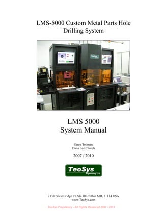
  • 1. TeoSys Proprietary - All Rights Reserved 2007 - 2013 2138 Priest Bridge Ct, Ste 10 Crofton MD, 21114 USA www.TeoSys.com LMS-5000 Custom Metal Parts Hole Drilling System LMS 5000 System Manual Emre Teoman Dana Lee Church 2007 / 2010
  • 2. TeoSys Proprietary - All Rights Reserved 2007 - 2013 Series 5000 Laser Micromachining System System Manual Rev. E Page 2 of 101 Table of Contents TABLE OF CONTENTS................................................................................................................................. 2  SAFETY............................................................................................................................................................ 5  HAZARDS ........................................................................................................................................................ 6  PROTECTIVE EYEWEAR ................................................................................................................................... 6  SAFETY INTERLOCKS....................................................................................................................................... 6  FACILITIES..................................................................................................................................................... 8  PHYSICAL ENVELOPE............................................................................................................................... 8  FRONT VIEW ............................................................................................................................................ 8  TOP VIEW.................................................................................................................................................. 9  SIDE VIEW ................................................................................................................................................ 9  SYSTEM POWER REQUIREMENTS ....................................................................................................... 10  REAR PANEL CONNECTIONS, COMPRESSED AIR AND VENTILATION........................................ 10  SYSTEM REAR PANEL ........................................................................................................................... 10  DIAGNOSIC SIGNALS.............................................................................................................................. 12  Q-SWITCH............................................................................................................................................... 12  FPS........................................................................................................................................................... 12  LD Current............................................................................................................................................... 12  EXTERNAL LASER CONNECTIONS ...................................................................................................... 13  External System Control .......................................................................................................................... 13  External Power Control........................................................................................................................... 13  VACUUM CONNECTIONS....................................................................................................................... 13  Debris Vent (Low Vacuum)...................................................................................................................... 13  High Vacuum............................................................................................................................................ 13  COMPRESSED AIR CONNECTION......................................................................................................... 13  VENTILATION........................................................................................................................................... 14  SYSTEM ENVRONMENTAL.................................................................................................................... 14  SERVICE ACCESS ..................................................................................................................................... 15  UNPACKING THE SYSTEM.............................................................................................................................. 16  MAJOR SYSTEM COMPONENTS............................................................................................................ 17  SYSTEM POWER UP................................................................................................................................... 18  GENERAL SYSTEM OPERATION ........................................................................................................... 28  ALTERNATE KEYENCE BASED DISCRIMINATOR........................................................................... 32  SYSTEM SHUTDOWN ................................................................................................................................ 33  LMS-5000 SUBSYSTEMS OPERATIONS, MAINTENANCE AND TROUBLESHOOTING............ 38  GENERAL SYSTEM DESCRIPTION................................................................................................................... 38  BASIC OPERATING SEQUENCE....................................................................................................................... 39  LADDER ASSEMBLY ...................................................................................................................................... 39  TRACKS AND VIBRATOR ............................................................................................................................... 42  SEPARATOR PLATE SYSTEM.......................................................................................................................... 47 
  • 3. TeoSys Proprietary - All Rights Reserved 2007 - 2013 Series 5000 Laser Micromachining System System Manual Rev. E Page 3 of 101 PICKUP TOOL SYSTEM .................................................................................................................................. 53  INDEXING PLATE SYSTEM ............................................................................................................................. 56  EJECTOR SYSTEM.......................................................................................................................................... 62  OPTICAL FLOW TESTER................................................................................................................................. 63  LASER SYSTEM ............................................................................................................................................. 66  SYSTEM OPTICS ............................................................................................................................................ 74  POWER METER.............................................................................................................................................. 79  THERMAL MANAGEMENT SYSTEM................................................................................................................ 80  SPIRICON OPHIR PROFILOMETER OPERATION............................................................................. 85  OPERATION ................................................................................................................................................... 86  CALIBRATION................................................................................................................................................ 90  TYPICAL RESULTS AND RECOMMENDED OPERATING PROCEDURE................................................................ 91  MAINTENANCE AND SERVICE............................................................................................................... 94  RECOMMENDED SPARE PARTS (REV E) .............................................................................................. 94  RECOMMENDED SERVICE SCHEDULE ............................................................................................. 100 
  • 4. TeoSys Proprietary - All Rights Reserved 2007 - 2013 Series 5000 Laser Micromachining System System Manual Rev. E Page 4 of 101 OVERVIEW It should be understood that the LMS-5000 Back Venting System is a custom, one of a kind, combination research tool, engineering development unit and high speed automated production system. As such this system should be considered the first attempt of a first generation new technology. The LMS-5000 Back Venting System project incorporated four significant parallel developments of note. 1. New, Pulsed 532nm Small Diameter Micromachining Technology – Until this system, it was difficult to impossible to find systems which would quickly, precisely and cleanly drill micron sized holes in thicker metals. In this project we developed and introduced the first production grade system capable of achieving this task. This green micromachining technology has opened up some new capabilities not previously available in industry. 2. Flying Objective Combination Laser and Inspection Linear Motion System – To provide maximum speed and flexibility for the automation system TeoSys opted to develop a completely new, over head flying objective system. Unique to this approach is the systems ability to move the laser objective and precision video microscope precisely anywhere in a 72 square inch area without distortion or speed detriment. The heart of the system is two sub-micron accurate linear drive stages. This system is capable of tenth micron accuracy (yes that is 100nm, less than the wavelength of visible light!!!) This technology is used in high end semiconductor research applications and is just now being applied for more traditional production systems. Though exceptionally complex, and difficult to integrate this system has turned out to be exceptionally reliable and stable. 3. New Optical Flow Tester Technology – The OFT was a grounds up, new development to produce a sub-micron capable measurement system which could analyzes hole position, cross-sectional area and equivalent calibrated barometric flow, all within a few hundred milliseconds. More impressive is the reality that this low noise precision optical instrument accomplishes these tasks in the high noise, high EMF, high vibration environment of a production automation system. By itself the OFT was a significant and unique development. There have been lingering doubts about the systems ability to discriminate flows within one SCCM. Recent improvements in the system ejectors, indexing plate and OFT optics however seem to point to better than ¼ SCCM discrimination in production environments. This bodes well for future developments and applications for this technology. 4. Unique Automation Solution and Software – The LMS-5000 also sports a completely new, ground up automation system. Unlike most automation projects, there were no legacy instruments or close correlates which could be used as springboard examples to build upon. The automation incorporates a few unique and interesting features;  Ultra-quiet Ladder Feed System – Initial testing indicated that traditional bowl feeders could interfere with the precision motion system, drilling quality and OFT. This unique ladder solution quickly feeds parts without vibration or electromagnetic noise.  Integrated Indexing System – This system loads, drills, measures and sorts parts simulations. Given the demands of the drilling and measuring system this is no small feat.  Non-Contact Ejection / Binning – Initial testing indicated that standard flat tracks and conveyers would clog the micro-holes. TeoSys developed and fielded a unique pneumatic system which never comes in contact with the newly drilled holes.  Tying all of this together is a highly complex, multiprocessor based system running three brand new software application suites, again all developed from the ground up for this application.
  • 5. TeoSys Proprietary - All Rights Reserved 2007 - 2013 Series 5000 Laser Micromachining System System Manual Rev. E Page 5 of 101 Safety This safety section should be thoroughly reviewed prior to operating the Drilling System described in this manual. Safety precautions contained herein and throughout the manual must be carefully followed to ensure that all personnel who operate or maintain the laser are protected from accidental or unnecessary exposure to the laser radiation. CAUTION Do not operate the laser with the cabinet parts removed. Use of controls or adjustments or performance of procedures other than those specified herein may result in exposure to hazardous radiation. Only a qualified technician should perform service. HAZARD 532nm Safety Glasses required when servicing the system, or operating the laser with cabinet parts removed and safety interlocks defeated. Avoid directly exposing skin or eyes to laser light. !! ! VISIBLE AND / OR INVISIBLE LASER RADIATION. AVOID EYE OR SKIN EXPOSURE TO DIRECT OR SCATTERED RADIATION Laser Type: Wavelength Range: Maximum Output Power: Maximum Pulse Energy: Nd YAG 532nm 50 Watts 100uJ CLASS I LASER PRODUCT DANGER! VISIBLE AND / OR INVISIBLE LASER RADIATION. AVOID EYE OR SKIN EXPOSURE TO DIRECT OR SCATTERED RADIATION Laser Type: Wavelength Range: Maximum Output Power: Maximum Pulse Energy: Nd YAG 532nm 50 Watts 100uJ CLASS I LASER PRODUCT VISIBLE AND / OR INVISIBLE LASER RADIATION. AVOID EYE OR SKIN EXPOSURE TO DIRECT OR SCATTERED RADIATION Laser Type: Wavelength Range: Maximum Output Power: Maximum Pulse Energy: Nd YAG 532nm 50 Watts 100uJ CLASS I LASER PRODUCT DANGER!!
  • 6. TeoSys Proprietary - All Rights Reserved 2007 - 2013 Series 5000 Laser Micromachining System System Manual Rev. E Page 6 of 101 Hazards Hazards associated with the laser system generally fall into the following categories:  Exposure to laser radiation, which may result in damage to the eyes or skin.  Electrical hazards generated in the power supplies or associated electrical circuits.  Secondary hazards such as the following: 1 – Moving parts in material handling systems. 2 – High noise levels. 3 – Pressurized lamps, hoses, cylinders, etc. 4 – EMI-RFI emissions from faulty equipment. 5 – Pressurized liquids and gasses. 6 – Mechanical hazards form enclosure doors and moving parts. The user should obtain a copy of the ANSI Z136.1, American National Standard for the Safe Use of Lasers, published by the American National Standards Institute, 1430 Broadway, New York, NY 10018, (212) 354- 3300. This publication is a comprehensive guide to the safety compliance standards required of laser users. ANSI is a non-government agency and has no enforcement authority; however, OSHA, the Occupational Safety and Health Administration, uses ANSI Z136.1 as its laser safety standard. Additional information can be obtained form the Laser Institute of America, 12424 Research Parkway, #130, Orlando, FL 32826, (407) 380-1553. Protective Eyewear It is not necessary to wear protective eyewear when operating the LMS-5000 System according to manufacturer’s specifications. If any interlocks should fail, it is imperative that the Drilling not be operated. Call TeoSys Engineering immediately for service. For service, it is recommended that laser-safe eyewear attenuated to the wavelength of 532 nanometers be worn at all times when the laser is firing with any interlocks defeated or doors open. Most standard lab or shop safety glasses are adequate protection for the typical user. Safety glasses should be equipped with protective side panels. Safety Interlocks The LMS-5000 SYSTEM contains 5 safety interlocks (Four top door interlocks and one front door interlock). The interlocks prevent operation of the laser when any doors are left open. The laser subsystem doors have safety interlocks. Any time the optics door is left open, the laser will not fire. Upper Door Interlock
  • 7. TeoSys Proprietary - All Rights Reserved 2007 - 2013 Series 5000 Laser Micromachining System System Manual Rev. E Page 7 of 101 The system front door also has a safety interlock. The laser will not fire when this door is left open. The amber glass panels are not interlocked since they are screwed in place and not generally intended to be removed during operation. The left most center amber panel is placed on magnetic strips for quick removal. There are internal shields which protect the operator during operation so running the system with this panel removed does not constitute a Class I violation. As an additional safety feature a protective cover has been added to the keyboard and mouse to prevent accidental motion. This cover is not interlocked and only necessary during motion system adjustments. Front Door Interlock
  • 8. TeoSys Proprietary - All Rights Reserved 2007 - 2013 Series 5000 Laser Micromachining System System Manual Rev. E Page 8 of 101 Facilities PHYSICAL ENVELOPE The LMS-5000 is a custom laser LMS-5000 System which consists of a welded frame enclosure and a free rolling laser power supply which fits in a cavity in the lower right side of the bottom table. FRONT VIEW Laser Power Supply Front ALL DIMENSIONS IN INCHES E ME R G AN C Y S HU T OF F PC #2 PC #1 Motion System#2 DriveRack Motion System#1 DriveRack R UN LM S5000 LAS ER MI CRO MA CHI NI NG SYS TEM O FF V AC U UM S TA R T P OW E R L AS E R E MI SS IO N P RE S SU R E P OW E R 0 10 0ps i 80 90 70 20 10 60 30 50 40 0 10 0ps i 80 90 70 20 10 60 30 50 40 E ng ine er in gL LC Teo Sys O pti cal Fl ow Te ster L AS E R O N/ O FF En gin eer ing LL C T eo Sy s PU SH T OS ET H IG H SE T P OI NT F AU L T F LO W (S C CM ) O N O FFH IG H S CA N G O OD G AI N O FF S ET L OW SE T P OI NT H IG HL OW PU SH T OS ET H IG H
  • 9. TeoSys Proprietary - All Rights Reserved 2007 - 2013 Series 5000 Laser Micromachining System System Manual Rev. E Page 9 of 101 TOP VIEW SIDE VIEW GOOD BAD ALL DIMENSIONS IN INCHES ALL DIMENSIONS IN INCHES
  • 10. TeoSys Proprietary - All Rights Reserved 2007 - 2013 Series 5000 Laser Micromachining System System Manual Rev. E Page 10 of 101 SYSTEM POWER REQUIREMENTS Nominal Input Voltage 220 VAC Voltage Range 198 VAC to 242 VAC Number of Phases 1Ø Frequency 50 / 60 Hz Nominal Current 11.4 amps Maximum Current 28.8 amps Nominal Power 2.6 KW Maximum Power 6.6 KW Connection Type Hard wired into junction switchbox > 12 Gauge (AWG) minimum (Ø A / B) > Safety Ground Fusing > Class: RK5 > Type: Time Delay, Dual Element > Symbol: FLNR > Current: 30 Amps > Fuses: 2 Connection Location Rear of system, lower center Power Quality Clean and devoid of surges, spikes and dropouts. Do not connect equipment on the same buss as other inductive equipment, or devices which produce sudden loads on main power. Suggest use of isolation transformer. REAR PANEL CONNECTIONS, COMPRESSED AIR AND VENTILATION SYSTEM REAR PANEL
  • 11. TeoSys Proprietary - All Rights Reserved 2007 - 2013 Series 5000 Laser Micromachining System System Manual Rev. E Page 11 of 101 Rear I/O Panel with UPS on Right Junction Switch Box, Open Input Side Output Side
  • 12. TeoSys Proprietary - All Rights Reserved 2007 - 2013 Series 5000 Laser Micromachining System System Manual Rev. E Page 12 of 101 DIAGNOSIC SIGNALS Q-SWITCH TTL (5VDC) reference signal used to monitor triggering sent from controller to laser. (This signal is used for diagnostic purposes only and should only be used by a qualified technician). FPS First Pulse Suppression. TTL (5 VDC) reference signal used to monitor the first pulse suppression signal sent from the controller to the laser. The FPS signal precedes the laser pulse signal (Q-Switch) for 2ms and functions as quench to reduce the magnitude of energetic initial pulses from the Q-Switch. (This signal is used for diagnostic purposes only and should only be used by a qualified technician). LD Current Laser Diode Current. This signal is a 0 to 10 VDC signal proportional to the laser diode drive current sent by the controller to the laser. (This signal is used for diagnostic purposes only and should only be used by a qualified technician).
  • 13. TeoSys Proprietary - All Rights Reserved 2007 - 2013 Series 5000 Laser Micromachining System System Manual Rev. E Page 13 of 101 EXTERNAL LASER CONNECTIONS External System Control Connector used by controller to externally trigger and manage laser power. External Power Control Connector used by the controller to externally manage initial laser power-up, pump circulation and HV power. VACUUM CONNECTIONS (Vacuum to be provided by facility) Debris Vent (Low Vacuum) > Low pressure high volume vacuum used for pickup of laser debris. > 3/8” Swagelok Fitting, B-600-61 3/8” x 3/8” Bulkhead Tube (System Side) > 10 – 20 mmHg, 10-25 CFM typical. > Should be externally regulated. > Plastic or Flexible Hose acceptable. High Vacuum > High pressure, low volume vacuum used to pick up cups on rotation arm assembly. > 3/8” Swagelok Fitting, B-600-61 3/8” x 3/8” Bulkhead Tube (System Side) > 25 mmHg, 2 to 5 CFM typical. > Should be externally regulated. > Plastic or Flexible Hose acceptable. COMPRESSED AIR CONNECTION (Compressed air to be provided by facility) Compressed Air – Low Pressure Higher Volume – AeroJet Optical Blow off > 10 PSI > 5 CFM > 3/8” Swagelok Fitting, B-600-61 3/8” x 3/8” Bulkhead Tube (System Side) > Clean, oil free, filtered to 1-5 um > Humidity between 30% to 50% NON-CONDENSING > Humidity is required for application to operate correctly. > Plastic or Flexible Hose acceptable. Compressed Air – (Shop Air) Higher Pressure Medium Volume – Internal Pneumatics > 75-100 PSI > 20 CFM > ¼” Swagelok Fitting, B-400-71-4, ¼” Tube x ¼” FNPT (System Side) > Clean, dry, oil free, filtered to 1-5 um > Plastic or Flexible Hose acceptable.
  • 14. TeoSys Proprietary - All Rights Reserved 2007 - 2013 Series 5000 Laser Micromachining System System Manual Rev. E Page 14 of 101 VENTILATION (Compressed air to be provided by facility) POSITIVE PRESSURE VENTILATION > Connection 4” diameter, male connector, clamp included with system. > Flow 200 CFM > Clean Filtered via HEPA system to <10um > Humidity 30% to 50% NON-CONDENSING > Humidity is required for application to operate correctly. > Excessive humidity can lead to condensation and LASER DAMAGE!! > Location On top of system, right rear as seen from front. 4” Positive Pressure Fitting (Top, Right, Rear of System as viewed from front) SYSTEM ENVRONMENTAL TEMPERATURE 70°F to 80°F (tolerance +/- 1°F) RATE < 5°F per hour This is an important specification. < 5°F means that the room temperature should vary a maximum of one degree every twelve minutes. A room temperature oscillation between +/- 5°F or greater of the nominal temperature, within 60 minutes, will fail this specification. Damage to the SHG module will occur if this specification is exceeded.! 200 CFM Input Filtered, Humidity and Temperature Controlled
  • 15. TeoSys Proprietary - All Rights Reserved 2007 - 2013 Series 5000 Laser Micromachining System System Manual Rev. E Page 15 of 101 HUMIDITY 30% to 50% NON-CONDENSING DUST Class 100,000 or better. VIBRATION No floor vibration perceptible to the touch. LASER WATER Clean, filtered deionized, steam distilled, 1 M Ohm resistance. > Approx 5 gal capacity. > Recommend having second 5 gal as backup. SERVICE ACCESS FRONT CLEARANCE 4’ REAR CLEARANCE 2’ LEFT SIDE CLEARANCE 4’ RIGHT SIDE CLEARANCE 2’ TOP CLEARANCE 2’ HAZARD Avoid operating system within high humidity environments. Condensing relative humidity above 70% should be avoided. If condensation is observed, suspend operation of the system. ! !
  • 16. TeoSys Proprietary - All Rights Reserved 2007 - 2013 Series 5000 Laser Micromachining System System Manual Rev. E Page 16 of 101 Unpacking the System The systems usually come packed in a crate. TeoSys will unpack the system and install into a place of the customers’ design. The systems are shipped usually on casters which are used for moving the system into place. These wheels will be removed and permanent feet will be attached to the system. The system should be placed in a dust free environment. The room should be temperature controlled for optimal performance of the system. After installation the LMS-5000 System fully Class I system should look like the following picture. Systems installation should only be conducted by TeoSys Engineering personnel.
  • 17. TeoSys Proprietary - All Rights Reserved 2007 - 2013 Series 5000 Laser Micromachining System System Manual Rev. E Page 17 of 101 Major System Components The LMS-5000 consists of a main system frame, a ladder assembly and a laser power supply. Most components are enclosed within the structure. Care should be taken not to lean on or otherwise touch the system during operation. Given that micro- drilling applications involve micron level precision, any vibration or impact will degrade system performance and product quality. Most importantly, avoid exposing the system to rapid changes in temperature and humidity. The facilities specification calls for less than a 5°F per hour rate of temperature change. The absolute temperature is less important than how quickly the temperature is changing inside the room. Primary Monitor Secondary Monitor Output Bins Profilometer Laser Power Supply Front Panel System Front Panel PC1 and PC2 Parts Ladder
  • 18. TeoSys Proprietary - All Rights Reserved 2007 - 2013 Series 5000 Laser Micromachining System System Manual Rev. E Page 18 of 101 System Power Up 1. Make sure that HEPA fan is on. This system should be left on all of the time. Debris Vent High Vacuu HEPA Fan High Vacuum Pump Debris Vent Pump AeroJet Nitrogen Compressed Air O NPump Switch Box
  • 19. TeoSys Proprietary - All Rights Reserved 2007 - 2013 Series 5000 Laser Micromachining System System Manual Rev. E Page 19 of 101 2. Turn on the debris vent power switch and open the valve. 3. Turn on the High Vacuum power switch and open the valve. 4. Open AeroJet Compressed Nitrogen valve. 5. Open compressed air valve 6. Check the front panel pressure gauges. The left gauge should be around 60 psi and the right gauge should be around 25inHg. With the accumulator the vacuum may take a few minutes to build as the tank is pressurized. This is normal; just take care not to run the automation until full pressure has been achieved. 7. Turn on the rear system power switch and the wall power switch and make sure that the laser power switch is in the on position. If power is correct, you should hear the fans on the laser power supply come on. ~60psi ~25inHg Main Power Switch Wall Power Switch O N ON
  • 20. TeoSys Proprietary - All Rights Reserved 2007 - 2013 Series 5000 Laser Micromachining System System Manual Rev. E Page 20 of 101 8. Turn on the front panel key switch. 9. Go to the back of the system and turn on the system UPS. This button takes about a second to ‘catch’. CB1 -Laser Circuit UPS Power Switch ON System Key Switch ON
  • 21. TeoSys Proprietary - All Rights Reserved 2007 - 2013 Series 5000 Laser Micromachining System System Manual Rev. E Page 21 of 101 10. After about 30 seconds the UPS will display ‘NORMAL’. At this point go to the front of the system and power on PC#1 with the momentary switch. 11. Within a few seconds the left monitor should begin to power up (light turns green). If the monitor does not power on immediately, switch monitors by hitting [ScrLk], [ScrLk], [Enter]. You should hear a beep if this is done properly. The left (Master Control) monitor should now come on and power up normally. After the PC#1 has finished loading you can power on PC#2 (Automation Control). No log-in is required. PC 1 Power Switch PC 2 Power Switch Change Monitor 2x ScrLk 1x Enter PC 1 Master Control Computer (KN1) Master Control Application Icon
  • 22. TeoSys Proprietary - All Rights Reserved 2007 - 2013 Series 5000 Laser Micromachining System System Manual Rev. E Page 22 of 101 12. Once the PC#2 is running, open the Automation System application to start motion system 2. The PC’s have been configured to automatically launch the proper application but if this does not occur, use the desktop icon to start the appropriate 13. Open the OFT application. The OFT application on motion system 2 (M2) is not required for system operation. This application is useful for viewing system performance over time. PC 2 Automation System Parts Feeding Control PC KN2 Automation System Application Icon Optical Flow Tester Application Icon (OPTIONAL)
  • 23. TeoSys Proprietary - All Rights Reserved 2007 - 2013 Series 5000 Laser Micromachining System System Manual Rev. E Page 23 of 101 14. Once open, position the applications on motion system 2 as shown; 15. Hit [ScrLk], [ScrLk], [Enter] to switch over to motion system 1 (M1) and launch the master control application. Once up the application should look like this;
  • 24. TeoSys Proprietary - All Rights Reserved 2007 - 2013 Series 5000 Laser Micromachining System System Manual Rev. E Page 24 of 101 16. Check the tracks for parts. Make sure that all covers are on the tracks before the motion system is initialized. Make sure that the vibrator is not turned on when performing any motion system initialization. Track Sensors Full Track with OFF Part Placement Area
  • 25. TeoSys Proprietary - All Rights Reserved 2007 - 2013 Series 5000 Laser Micromachining System System Manual Rev. E Page 25 of 101
  • 26. TeoSys Proprietary - All Rights Reserved 2007 - 2013 Series 5000 Laser Micromachining System System Manual Rev. E Page 26 of 101 17. Next initialize the motion system (Button 1). Both motion controls (M1 and M2) will begin to initialize. Avoid contact with any motion component during initialization. Initialization takes about a minute to complete. 18. Verify that parts are aligned with separator plate and parts feed smoothly. 19. Next enable the laser (Button 2). The laser will now power up automatically. If properly initialized, no faults will show on the laser front panel. Faults are also displayed on the front panel of the M1 Master Control application. Laser Fault Indication LED NOTE: DO NOT RUN LASER WITH ANY FAULT LIGHTS INDICATING RED Fault Indication (RED) No-Fault Indication
  • 27. TeoSys Proprietary - All Rights Reserved 2007 - 2013 Series 5000 Laser Micromachining System System Manual Rev. E Page 27 of 101 20. Clean the indexing table, pickup tool, tracks and ladder assemblies. Generally these operations should be done every ten thousand parts or once per day. 21. Make sure that the parts in the ladder bins are above the minimum line. Minimum Parts Level Line
  • 28. TeoSys Proprietary - All Rights Reserved 2007 - 2013 Series 5000 Laser Micromachining System System Manual Rev. E Page 28 of 101 General System Operation 1. Turn on the track vibrator and verify that a part has fed into a separator plate slot. In general parts should feed into the separator plate slots very quickly (within ½ second). If the feeding takes more than one second then the track feed probably needs adjustment or cleaning. 2. To fill the tracks with parts press the RUN Ladder Feed button. This will run the ladders and begin to feed parts into the system. It is generally better to ‘prime’ the system with parts before running the automation. 3. To initiate operation put the system into [PURGE] mode and hit [START]. This will load parts into the complete system before starting the laser. It is not desirable to run the laser without parts on the indexing plate. 4. Once the system is fully primed with parts [STOP] operation, switch to [DRILL] mode then hit [START]. Track Vibrator Valve
  • 29. TeoSys Proprietary - All Rights Reserved 2007 - 2013 Series 5000 Laser Micromachining System System Manual Rev. E Page 29 of 101 5. Use the live video display to monitor systems operation. There are 4 cameras in this system each of which will show a different part of the drilling process for monitoring purposes.  The [Drill Cam] monitors the drilling operation as viewed from the objective.  The [Drop Cam] monitors the dropping of the part by the pickup tool onto the indexing plate.  The [Sep Cam] monitors the feeding of the parts from the tracks onto the separator plate.  The [Eject Cam] monitors the Good Ejector.  The system can be set to sequence the video via the [Video Sequencing On/Off] button. Part Placement Area From Pick & Place
  • 30. TeoSys Proprietary - All Rights Reserved 2007 - 2013 Series 5000 Laser Micromachining System System Manual Rev. E Page 30 of 101 6. During drilling the Optical Flow Tester (OFT) slowly drifts. This drift is due to many factors, primary of which is debris which collects on the indexing plate. This drift is very slow and gradual and can be easily compensated for by using the Auto Nest Cal feature. The Auto Cal feature can be found on the [MEASUREMENT] tab. Once every hour (or 1000 parts) switch the Auto Nest Cal feature from [OFF] to [ON]. The system will begin to automatically adjust the OFT sliders until all of the nests are producing the same responses. After five minutes (or when the sliders are stable and not moving) turn off the Auto Nest Cal feature and continue to run the system. Auto Nest Calibration does not slow the system down or in any way
  • 31. TeoSys Proprietary - All Rights Reserved 2007 - 2013 Series 5000 Laser Micromachining System System Manual Rev. E Page 31 of 101 impact the quality of the drilling so it can be used whenever the operator wants to check OFT operation. 7. During operation the flow measured for each part is displayed on the [USER] tab. The average and standard deviations are for the last ten parts. The Position display shows, in microns, how far the drill hole is from the expected center. A summary of all of the measurement information is displayed in the center and a pie chart of the same information is displayed on the right. Refer to the LMS-5000 Systems Operations, Applications and Software manual for more details of operating the system and its software.
  • 32. TeoSys Proprietary - All Rights Reserved 2007 - 2013 Series 5000 Laser Micromachining System System Manual Rev. E Page 32 of 101 Alternate Keyence Based Discriminator The system has been modified to discriminate between two different part shapes and sizes.. The Keyence discriminator (pictured below) does require adjustment between parts switchovers however it has the advantage that it makes fewer errors. This discriminator determined orientation of the part and via an analog output to the software running on PC #1, determines the spin direction that the pick and place arm places the part on the central index plate for later drilling. The Keyence systems operation and adjustment are covered later in this document. Either discriminator will work. It is left to the user’s discretion as to which discriminator is appropriate for the application. Keyence Fiber Based Discriminators One is for the HC Shaped Part The other is for the FK Shaped Part Fiber Positioning Adjustment Bracket Part Orientation Detection Fibers for Keyence Sensor Part
  • 33. TeoSys Proprietary - All Rights Reserved 2007 - 2013 Series 5000 Laser Micromachining System System Manual Rev. E Page 33 of 101 System Shutdown 1. Once production is complete [STOP] the system and turn the [LASER CURRENT] down to 0.00. 2. Verify that the laser current on the laser front panel has been reduced (usually down to approximately one amp). This gives the laser time to cool off after operation. Allow a Minimum of 5 minutes before closing the master control application and turning off the system. Laser Current Display Laser Current
  • 34. TeoSys Proprietary - All Rights Reserved 2007 - 2013 Series 5000 Laser Micromachining System System Manual Rev. E Page 34 of 101 3. Next, close the M1 Master Control Application. The laser power supply should power off at this point however the main pump should still be running. Current on the display should now be zero. Close and exit the application via [FILE]
  • 35. TeoSys Proprietary - All Rights Reserved 2007 - 2013 Series 5000 Laser Micromachining System System Manual Rev. E Page 35 of 101 During power off the application will automatically time down five minutes to make sure that the laser has cooled properly. 4. Hit [ScrLk], [ScrLk], [Enter] to switch over to motion system 2 (M2) then close and exit both applications. 5. Shutdown PC#2 via the [START] button. 6. Hit [ScrLk], [ScrLk], [Enter] to switch over to motion system 1 (M1) and also shutdown PC#1 via the [START] button. 7. Power off the UPS at the rear of the system (hold button for one second again until the UPS catches and powers off). 8. Power off the key switch on the front panel. Shut Down PC#2 via [START] button UPS Power Switch OFF
  • 36. TeoSys Proprietary - All Rights Reserved 2007 - 2013 Series 5000 Laser Micromachining System System Manual Rev. E Page 36 of 101 9. Leave the main system power switch on for at least 5 minutes before shutting off main power. This gives the fans at the back of the laser power supply time to cool the electronics inside the system. 10. Shut off main wall power. System Key Switch OFF Main Power Switch Wall Power Switch O F F OFF
  • 37. TeoSys Proprietary - All Rights Reserved 2007 - 2013 Series 5000 Laser Micromachining System System Manual Rev. E Page 37 of 101 11. Shut off all gas and vent supplies EXCEPT the HEPA vent. Leave the HEPA vent running. The HEPA vent baffle should be set to 50%. 12. Close all panels and doors. This will keep dust out of the system. HEPA Baffle Control HEPA Fan LEAVE HEPA ON!
  • 38. TeoSys Proprietary - All Rights Reserved 2007 - 2013 Series 5000 Laser Micromachining System System Manual Rev. E Page 38 of 101 LMS-5000 Subsystems General System Description The LMS-5000 consists of a 532nm Nd YAG Laser, Control System, Motion System, Structure, Power Supply and Software. The Laser consists of two major elements. The first is the laser head which is integrated into the upper systems structure. The second element of the laser is its power supply which resides in a cavity below the system. The laser power supply is not attached to, or otherwise part of the main system structure. The control system consists of two PC’s and an integrated PLC (Programmable Logic Controller) which is referred to in this documentation as the Ensemble controller. The motion system consists of a ladder assembly, a track assembly, a separator plate system, a pickup arm, an indexing plate and an ejector system. The structure consists of three enclosures supported by a single welded frame. The upper enclosure houses the laser head, beam delivery and X-Y stages. The middle enclosure houses the parts handling system and the optical flow tester. The lower enclosure houses the PC’s, motion amps, power delivery, power supplies and transformers, UPS, DIN rail system, KVM and Laser Power Supply. Custom software resides on both PC’s as well as the Ensemble controller. Primary Monitor (M1) Secondary Monitor (M2) Output Bins Profilometer PC & Integrated Profilometer Camera and Optics Laser Power Supply Front Panel System Front Panel PC1 and PC2 Parts Ladder UPPER SECTION MIDDLE SECTION LOWER SECTION Separator Plate, Pick and Place and Rotary Pickup tool Indexing Plate and OFT Power Meter & SHG Control
  • 39. TeoSys Proprietary - All Rights Reserved 2007 - 2013 Series 5000 Laser Micromachining System System Manual Rev. E Page 39 of 101 Care should be taken not to lean on or otherwise touch the system during operation. Once running the system should not need continuous adjustment. An operator should be present just for monitoring purposes. Basic Operating Sequence For purposes of clarity we will follow the progression of the parts through the system and describe each major assembly and feature. The parts flow, from left to right. The parts start in a bin on the ladder assembly, through the tracks and onto the separator plate. The ladder assembly ensures the parts are oriented cup side down, on the tracks. Once on the Separator plate the parts are inspected for orientation, and then transferred to the indexing plate via pickup tool. The pickup tool (or rotary arm) rotates the part into one of two positions, depending upon what was detected by the discriminator when the parts were on the separator plate. Once on the indexing plate the parts are clamped and move to be drilled by the laser. After drilling the parts move from the drill position to the OFT (Optical Flow Tester) position. At this point the holes are measured for diameter (flow) and position. Good parts are then ejected into the ‘good’ pneumatic track and bad parts ejected into the ‘bad’ track. Each track ends up into a bucket at the far right side of the system. The tracks are tubular to avoid any flat surfaces coming into contact with the drilled holes. The holes will clog easily and should not be touched. Ladder Assembly Description – The ladder assembly, as described above, pulls the parts from a bin, along a series of ladders. The ladders are specially constructed to favor one parts orientation (cup in) over another (cup out).
  • 40. TeoSys Proprietary - All Rights Reserved 2007 - 2013 Series 5000 Laser Micromachining System System Manual Rev. E Page 40 of 101 With the setting of an appropriate angle to the ladder, the cups will reliably fall if pulled cup in from the bin. The angle of the ladders is adjusted via two set screws and locked in place by the eight locking bolts. Ladder Locking & Angle Care has to be taken in that adjusting the ladder angle can distort or move the track positions. It is best to determine the best ladder angle without the tracks attached, then connect the tracks once, after all angle adjustments have been made. The belt of the ladder assembly is adjusted via two adjustment set screws accessible from the top of the ladder assembly. Ladder Angle Adjustment Screw Ladder Locking Screws (4 each side)
  • 41. TeoSys Proprietary - All Rights Reserved 2007 - 2013 Series 5000 Laser Micromachining System System Manual Rev. E Page 41 of 101 The belts vertical position is adjusted with these two adjusters. The belt should make clean contact with the cups, but not rest on or otherwise drive the cups into the tracks. A horizontal belt is usually a good sign of adjustment. Vertical Ladder Position Track alignment is achieved by adjusting the vertical ladder positions and by making adjustments to the track position. Vertical ladder position changes can be accomplished by making small adjustments to the ladder home position flag. By loosening the brass flag (with two locking screws) and adjusting vertical position one can move the ladder position with respect to the track. Ladder Home Flag Horizontal Belt with good ladder – track alignment.
  • 42. TeoSys Proprietary - All Rights Reserved 2007 - 2013 Series 5000 Laser Micromachining System System Manual Rev. E Page 42 of 101 Once the ladders are adjusted to top dead center the tracks can be adjusted as well. Track System (Rollercoaster) The tracks are aligned with the ladders via four clamp screws on either side of the tracks. Track Alignment to Ladder Rungs By loosening the track clamps one can align the track with respect to the ladders. There should be a small gap of about .016-.025” between the end of the ladders and the beginning of the track. A track cover can be used as a spacing device. Vertical alignment is accomplished by loosening the vertical locking screw (located behind the clamps in this picture). The track should be flush with, or just Track Clamps with gap spacer in place. Ladder Home Flag
  • 43. TeoSys Proprietary - All Rights Reserved 2007 - 2013 Series 5000 Laser Micromachining System System Manual Rev. E Page 43 of 101 below the level of the ladders. A precision alignment block is used to verify alignment for each ladder against the track. Track alignment should be close enough to allow the alignment blocks to move freely from ladder to track for each ladder.
  • 44. TeoSys Proprietary - All Rights Reserved 2007 - 2013 Series 5000 Laser Micromachining System System Manual Rev. E Page 44 of 101 If individual tracks need to be adjusted, loosen the four metric (M4) screws that hold the tracks on and adjust as necessary (special tools provided). Track Cleaning The tracks and covers should be cleaned regularly and checked for damage (burrs or scratches). Metal tools should never be used directly on the track material. This will cause damage to the tracks and hinder parts flow. Ports are provided below the tracks and above the sensor section to aid in clearing any obstructions. Access Ports Tracks Sensor section with two sensors attached to top cover.
  • 45. TeoSys Proprietary - All Rights Reserved 2007 - 2013 Series 5000 Laser Micromachining System System Manual Rev. E Page 45 of 101 Track Sensor Alignment Track alignment is accomplished via a set of end clamps. These clamps must be in good condition and assembled properly for parts to flow smoothly from section to section. The sensors should be adjusted so that they robustly detect parts when present below the sensor head. This is usually when the sensor head is flush with the bottom of the lid. There is a small light on the top of each sensor which can be used to determine the presence of a part below the head. If the sensor is adjusted too low, the lid will not fit properly or the sensors will hang on parts causing a jam. The sensor has been designed for a specific combination of materials so if new parts are introduced they must be tested with the sensor system before running production. Track Vibrator The tracks require a vibrator to ensure proper parts flow. The setting of the vibrators speed is critical. If the speed is too low, the vibrator will shake the system causing vibration on the video display. If the speed is too high, the parts will jump off of the tracks. Experimentally we have found that 200Hz is approximately a good excitation frequency. NOTE: The vibrator MUST be replaced every 3 months. It will become dirty and not function properly. This not only affects the part loading onto the separator plate but also causes much deviation in the size and shape of the holes being drilled on the parts.
  • 46. TeoSys Proprietary - All Rights Reserved 2007 - 2013 Series 5000 Laser Micromachining System System Manual Rev. E Page 46 of 101 Typically 200Hz is obtained with about 10psi on the vibrator regulator. 100 Hz, for example, shakes the video display and distorts the drill Ovality or circularity. As a specification we recommend 200 Hz +/- 25Hz. This frequency should be checked at least weekly. The vibrator slowly changes speed as it ages and compressed air contaminants can also significantly shift the speed / pressure relationship. Acceptable Vibration Level 200Hz Center Frequency @ 10 psi
  • 47. TeoSys Proprietary - All Rights Reserved 2007 - 2013 Series 5000 Laser Micromachining System System Manual Rev. E Page 47 of 101 The specific tool used to collect the vibration data is not important. The graphs above, for example, were collected using a iphone 3G running Signal Scope 1.2 from Faber Acoustical. Any capable DSM / Microphone system should suffice. Separator Plate System Description Aligning the tracks to the separator plate is a critical adjustment. Before starting the alignment process home the separator plate (Y axis, motion system #2). This will provide a proper reference for the next alignment steps. If the parts don’t flow easily from the track to the plate then alignment is necessary. Once a new slot is indexed to the track a part should snap into position within ½ second. Transfers more than one second indicate a problem with alignment, vibration, dirt or plate position. Track – Plate Alignment The same alignment blocks used for the ladders will be needed to check track / plate alignment. The track should be even with, or just above the separator plate. We recommend about .005” as a reasonable step. The vertical adjustment is accomplished via a small lift stage. Unacceptable Vibration Level 100Hz Center Frequency @ 4 psi
  • 48. TeoSys Proprietary - All Rights Reserved 2007 - 2013 Series 5000 Laser Micromachining System System Manual Rev. E Page 48 of 101 To obtain the proper vertical position, loosen the vertical locking screw and adjust the vertical lift adjustment. To adjust the horizontal position grossly, use the lower gross adjustment. Precision adjustments will be made via the upper Push Pull horizontal adjustment. Plate / Cup Insert Alignment Due to several separator hardware faults which occurred during the initial system installation, the separator plate has some inaccuracies at certain locations which TeoSys was able to map. In order to correct for these inaccuracies, the application software adds and subtracts values from the “expected” move position of 22.5°. These values are read in from an external file and can thus be changed at any time. The current values in these files for the two different parts numbers are as follows: Table 1: Table of offset values for FKs & HCs Vertical Lift Adjustment Vertical Locking Screw Gross Horizontal Adjust Locking Screw Rotation Lock
  • 49. TeoSys Proprietary - All Rights Reserved 2007 - 2013 Series 5000 Laser Micromachining System System Manual Rev. E Page 49 of 101 Figure 1 : HC Separator Pocket Precision, Push Pull Horizontal Adjust Parts Pusher Locking Clamp Screws In / Out
  • 50. TeoSys Proprietary - All Rights Reserved 2007 - 2013 Series 5000 Laser Micromachining System System Manual Rev. E Page 50 of 101 To make fine horizontal adjustments, loosen the opposing side (brass ¼-20 bolt) then tighten the locking side. This will move the track left and right. Motion along the track (in and out) is accomplished by loosening the track locking clamp screws and sliding the track in and out. There should be a gap of at least .016” between the track and the separator plate. The tooling block should also freely move from track to plate if everything is aligned properly. Parts Pusher There is a brass spring like device used to ensure that the parts don’t move off of the separator plate slots. The spring should be just touching the separator plate with a very light force. The spring tension is adjusted via a red knob on the top of the pusher. Keyence Sensor Alignment The Keyence sensor should be adjusted to provide the maximum difference between the ‘on’ and ‘off’ states. The green numbers are threshold set points (for on or off). The red numbers are the actual fiber readings. The closer the actual numbers are to the set points, the more likely that a false decision will be made. With valid parts loaded onto the separator plate, move from slot to slot to validate the widest possible spread between on and off (part facing in or part facing out or non-existent part). Adjust the micro calipers in X, Y and Z to obtain best center and discrimination.
  • 51. TeoSys Proprietary - All Rights Reserved 2007 - 2013 Series 5000 Laser Micromachining System System Manual Rev. E Page 51 of 101 Blow-Off Tool In case the vacuum based pickup tool doesn’t remove a part from the separator plate there is a blow off tool which removes part before it can cycle back and damage the tracks. The blow-off tool jets a stream of air into the plate and catches any loose parts into a catch bag. The tool can be removed and adjusted via a ¼-20 bolt located at the base of the assembly. Adjust the blow off tool air regulator (shown below) to obtain a good blow-off, with minimal noise and vibration. X Y Z
  • 52. TeoSys Proprietary - All Rights Reserved 2007 - 2013 Series 5000 Laser Micromachining System System Manual Rev. E Page 52 of 101 Blow-Off Tool Regulator
  • 53. TeoSys Proprietary - All Rights Reserved 2007 - 2013 Series 5000 Laser Micromachining System System Manual Rev. E Page 53 of 101 Pickup (Pick & Place) Tool System Description The vacuum based pickup tool moves parts from the separator plate to the indexing plate. The tool is comprised of a rotary stage (X), lift stage (Z) and tool rotation motor (U). Figure 2 : Pickup Tool Assembly Pickup Tool Maintenance The pickup tool can be removed by removing the ¼-20 shoulder bolt which retains the breakaway feature. The number of spring washers below the head of this screw is critical so if this part is to be removed, do not lose any of its components. The current design and spacing uses three wave washers, one of which is opposing. Pickup Vacuum Solenoid Manual Z Knob Z Axis Lift Stage (Up & Down) Breakaway Feature (Failsafe for U Rotary Axis) Rotation MicroMo Motor U Rotary Axis Clamp Straightness Lock Pickup Tool U Rotary Axis X Rotary Stage Vacuum Line
  • 54. TeoSys Proprietary - All Rights Reserved 2007 - 2013 Series 5000 Laser Micromachining System System Manual Rev. E Page 54 of 101 Figure 3 : Spring Washer Configuration, Total Stack Height = 0.1” Pickup Tool Installation When installing the pickup tool the spacing between the spring plunger and the base should be even all the way around. A nominal gap of 0.031” is typical but consistency is more important than a specific gap value. Also, when viewed from the front, the spring plunger should be in the center of the arm base. Uneven spacing would tend to indicate that the tool has not been installed properly. If the pickup tool is not installed properly the then the pickup, drop-off positions will be in error and an arm crash is likely. Left, Left, Right Pickup Arm Breakaway Spacing
  • 55. TeoSys Proprietary - All Rights Reserved 2007 - 2013 Series 5000 Laser Micromachining System System Manual Rev. E Page 55 of 101 After properly installing the pickup tool one should connect the vacuum line. The line should clear all obstructions through the two main part orientation positions and Home position (Home, Pos A, and Pos B). Pickup Tool Hose Positioning Tucking the hose behind the arm and controlling its length will keep the tool from jamming. Also, make sure that the rotary flag goes through the center of the flag sensor (located at the rear off the pickup tool. Adjusting tool height via the shaft set screw will accomplish this alignment. Pickup and Drop Off Positions By entering maintenance mode on motion system number two software application one can gain access to the joystick and position adjustment screens in order to set the pickup and drop off positions for all three axes, X, Z and U (see figure below). These positions will be saved so they only have to be set after a change to the hardware has been made. There is a set for the HC part as well as a set for the FK part as the parts have differing geometries. For manual motion activate the joystick (red button) below and hit the appropriate stage for motion. Speed can be adjusted via the four radio buttons (slow, medium, fast, ultra fast). The position registry buttons are located above the joystick. The button commands the stage to go to a specific position. The data entry box (arrow driven) alters the specific position. After making changes to a specific position the [Save Positions] button will record the changes. It is imperative that you not mix joystick and position button commands. This can confuse the motion system and cause a crash. CAUTION Using the position buttons and joystick can cause damage to the system or its components. The necessity for the change of these variables may indicate a larger physical problem. Always consult with the factory before making changes to these positions. Home Position A Position B Position !!
  • 56. TeoSys Proprietary - All Rights Reserved 2007 - 2013 Series 5000 Laser Micromachining System System Manual Rev. E Page 56 of 101 Always save a screen capture of your current and previous settings. This record is helpful with future diagnostics. Cleaning the tool and verifying that there is good vacuum (~20 to 25mmHg) is important. Also, the tool should be relatively rigid in its mount with no perceptible vertical, lateral or rotational backlash. Indexing Plate System Description The indexing plate is an eight position rotary table which accomplishes several simultaneous tasks. First, it receives the part from the rotary arm (Drop Off). Next it clamps and drills the part at the laser station. Then it measures the part using the optical flow tester (OFT). Finally it ejects the part via one of two ejectors (good and bad position). There is a small pickup magnet which, if there is an ejector failure, will snatch parts off of the indexing plate.
  • 57. TeoSys Proprietary - All Rights Reserved 2007 - 2013 Series 5000 Laser Micromachining System System Manual Rev. E Page 57 of 101 As the indexing plate rotates, clamps which ride on a cam follower system, open and close as necessary. Index Plate Stations There are eight stations. Station one is the drop off point. The rotary arm places the part into the pocket and nudges it into the corner. This nudge is critical otherwise the part will not seat properly. Manifold Cam Slide Clamp Ejector AeroJet Indexing Plate
  • 58. TeoSys Proprietary - All Rights Reserved 2007 - 2013 Series 5000 Laser Micromachining System System Manual Rev. E Page 58 of 101 Station three is the drill station which allows the beam to pass through the part and the bottom illuminator to illuminate the hole from below. Station five is the flow measurement point where the OFT illuminates the part from below and measures the amount of light passing through the drilled hole. Good and bad parts are ejected on station seven and eight. Figure 4 : Index Plate Stations During the drilling process the indexing plate does not move. The beam orbits above the stationary part. This is accomplished via a flying objective and will be covered in following sections. The key point, however, is that the laser drills the part and passes through the indexing plate and its insert to be trapped by a beam stop shown in the picture below. The beam stop is found below the indexing plate. This device reflects the laser energy into an absorber. The beam stop system is comprised of a beam splitter (green mirror) and an absorber. The mirror passes the red light of the illuminator and reflects the green light of the laser. The beam stop doesn’t generally require service other than checking the condition of the turning mirror and aligning it to ensure that the laser’s energy is passing into the absorber.
  • 59. TeoSys Proprietary - All Rights Reserved 2007 - 2013 Series 5000 Laser Micromachining System System Manual Rev. E Page 59 of 101 Figure 5 : Index Plate Laser Beam Positioning Index Plate Insert Adjustment As for adjustment, the parts can be translated with respect to the indexing plate via movement of the bronze insert with respect to the indexing plate. The inset is held in position via two mounting screws and can be nudged from side to side, front to back. The system’s video display should be used a reference during this alignment process. Laser Process thru Indexing Plate Indexing Plate Insert Part Laser Beam
  • 60. TeoSys Proprietary - All Rights Reserved 2007 - 2013 Series 5000 Laser Micromachining System System Manual Rev. E Page 60 of 101 Various cross hairs and alignment tools are available for alignment assistance and the video display has a resolution of about two microns which should be sufficient for most drilling requirements. Once the inserts are all aligned to each other then the motion system and video can be aligned to the insert location via the drill positions (X and Y for HC and FK). Setting the drill locations and choosing the metric conversion factors are described in the system software manual. Aligning the Camera Position to Center the Hole in the Video Display To align the drill to the center of the visible display once can adjust the camera mirror (shown below). Generally, to adjust the camera mirror the front door assembly should be removed. Camera Mirror Camera Video Position Adjusting Screws (x & y)
  • 61. TeoSys Proprietary - All Rights Reserved 2007 - 2013 Series 5000 Laser Micromachining System System Manual Rev. E Page 61 of 101 Index Plate Insert Maintenance – On a daily basis the insert thru holes should be inspected, cleaned. If laser debris has collected the users may find it necessary to run a drill bit through the drill hole. Polishing the insert may also be helpful in eliminating scratches and damage. Also, the magnetic pickup should be cleared of any loose parts. As for longer term maintenance, the main concern is smooth mechanical operation. Make sure that the manifold seals are good, that the slides move smoothly, that the clamp and pivot all are clear and working properly. The biggest issue is usually finding and removing stray cups which can jam these mechanisms. Finally, make sure that the vacuum pickup and aero jet systems are aligned. The AeroJet works best at 2 to 3 psi. Ejector Manifold Seal Slide Pivot Clamp & Bearing Laser Hole Vacuum Pickup Magnetic Pickup Push / Pull units to position the pick and place rotary stage
  • 62. TeoSys Proprietary - All Rights Reserved 2007 - 2013 Series 5000 Laser Micromachining System System Manual Rev. E Page 62 of 101 Ejector System Pressure Adjustment The only significant adjustment of the ejector system is to ensure that the pressures are adjusted properly to allow good ejection and that assist gas is sufficient to pass the parts through to the bins. For good ejects a range of 8 to 13psi seems to work well. Assist gas settings of 2.5 psi is usually sufficient to ensure good funnel ejection. Part Catch Funnel Adjustment Funnel adjustment can be accomplished by moving adjusting screws which rotate and translate the funnels. Ejector Regulators Assist Gas
  • 63. TeoSys Proprietary - All Rights Reserved 2007 - 2013 Series 5000 Laser Micromachining System System Manual Rev. E Page 63 of 101 Optical Flow Tester Description The optical flow tester illuminates the bottom of the cups with an intense laser source then measures the position and amount of light passed through the part. Decisions regarding part quality are made with this data. It is imperative that the indexing plate not be modified outside of the specifications in the drawings because it may affect the performance of the OFT. The OFT is dependent upon the laser light which passes through the index plate and then through the part. If the light is obstructed then the OFT will not function reliably. NOTE: Verify that the holes which allow the light to go through the bottom of the part are never obstructed. The holes may be made larger but they should never be made smaller than those on the original (TeoSys) designed index plate. Translation Screws Rotation Screws Funnel Adjustment
  • 64. TeoSys Proprietary - All Rights Reserved 2007 - 2013 Series 5000 Laser Micromachining System System Manual Rev. E Page 64 of 101 OFT Data Display on KN2 The OFT data is consumed in several ways but its primary user interface is the OFT application (on M2). The display shows the centration (how close the part is in the natural center of the OFT), as well as total flux (flow) as well as actual voltage. Secondary Front Panel Display Access Port Laser Source Position Adjustment (4)
  • 65. TeoSys Proprietary - All Rights Reserved 2007 - 2013 Series 5000 Laser Micromachining System System Manual Rev. E Page 65 of 101 OFT Alignment There are no user serviceable parts inside of the OFT. If the part position shifts with respect to the OFT there are four adjustments which translate the entire OFT to the correct position. To adjust the OFT index a known, good part into the OFT measurement position. Open the OFT application on M2. Loosen slightly the two OFT base plate screws if they are not already slightly loose (located just behind front panel). Use the front, rear and side adjusters as push - pulls to precisely move the OFT to the correct position. For moves to the right there is a notch built into the front left adjuster. This notch can be used to translate the OFT to the right. You will know when the OFT is correctly positioned when the diff number on the position display is at its lowest and the OFT is reading a reasonable flow (ON CENTER and IN SPEC). To verify OFT performance load eight calibration parts (parts of identical flow and position) onto the indexing plate. To conduct this experiment you will have to remove the manifold and clamp cam. The idea to is to rotate the same calibration parts through the OFT and collect flow data on the system with the unit running with the pickup tool disabled and ejectors disabled. If all is well you will see the same responses (same calibration data) from the OFT from run to run, part to part. OFT Maintenance Depending upon the amount of dust in the air the only user serviceable element is the front laser mirror. Carefully clean the mirror with a clean dry cloth. Minimal force is important to avoid moving the alignment. Also, avoid resting on or moving the OFT enclosure. Small changes in alignment may occur which would then need to be accounted for by re-aligning the OFT with respect to the part center. Front Left Adjuster Side AdjusterFront Middle Adjuster Rear Adjuster
  • 66. TeoSys Proprietary - All Rights Reserved 2007 - 2013 Series 5000 Laser Micromachining System System Manual Rev. E Page 66 of 101 Laser System Description The laser used in the application is a 25 Watt 532nm diode pumped, Q-switched high energy pulsed unit. The major components of the laser are outlined in the following picture: Laser Mirror
  • 67. TeoSys Proprietary - All Rights Reserved 2007 - 2013 Series 5000 Laser Micromachining System System Manual Rev. E Page 67 of 101 Figure 6 : Laser Rail with Descriptions HeNe Side Figure 7 : Laser Rail with Descriptions at Telescope Side ShutterQ-Switch TeoSys Alignment Tool Power Meter SHG Module Telescope System Laser Rear Side Laser Front Side Diode Module SHG Module IR High Reflector Bragg Angle Adj. IRHR GNHR IRGNOC GNHR Ring Adjust Class III Only!
  • 68. TeoSys Proprietary - All Rights Reserved 2007 - 2013 Series 5000 Laser Micromachining System System Manual Rev. E Page 68 of 101 Laser Components The TeoSys alignment tool is used for Class III rails off alignment and is not intended to be used by the end customer. The IR high reflector is a cavity mirror coated for 1064nm (IR). The Q-Switch is an optical capacitor that converts the constant wave laser to a short pulsed laser. The diode module uses red laser diodes to excite a Nd-YAG crystal to generate 1064nm constant light. The shutter is an intra-cavity window which allows or disallows laser emission. The SHG (Second Harmonic Generator) module converts 1064nm IR light into 532nm green light. The SHG module has three active optical elements. First is the 532nm high reflector (left side). Next is the conversion crystal (inside) and last is the 1064/532nm output coupler (right side). There are no user serviceable components in the SHG module. Other than Class I alignment (adjusting the OC and HR’s) contact TeoSys for factory service. CAUTION Do not attempt to service the SHG. These parts are TeoSys proprietary. Call for Factory Service if you suspect that this element needs service. Laser Power Meter & Telescope The next major element is the power meter. This meter’s results are displayed on the right side of the system as well as in the software application. When the meter is enabled the laser does not pass through. The final element in the laser is the telescope. This optic expands and manipulates the divergence of the output beam. Other than pointing, the telescope should not be adjusted, especially the A and B rings. These adjustments are TeoSys proprietary and require a qualified engineer to manipulate. CAUTION Do not adjust the A and B rings of the Telescope. These adjustments are TeoSys proprietary. Call for Factory Service if you suspect that this element needs service. !! !!
  • 69. TeoSys Proprietary - All Rights Reserved 2007 - 2013 Series 5000 Laser Micromachining System System Manual Rev. E Page 69 of 101 Laser Alignment There are three types of alignment activities for the LMS-5000. Class I is a general adjustment of the three main optical mirrors in the laser cavity (IRHR, GNHR, IRGNOC). For sophisticated users with appropriate tools this alignment is possible. Class II alignment covers basic minor alignment (not replacement) of components downstream of the laser and again should be within sophisticated user’s capabilities. Major rails off or component replacement alignment is defined as Class III and should be conducted by TeoSys factory engineers. The following are included within the Class III alignment: CLASS III (TEOSYS ONLY) SERVICE ACTIVITIES LASER  1064nm high reflector mirror rotation or replacement (IRHR)  532nm high reflector mirror rotation or replacement (GNHR)  532/1064nm output coupler mirror rotation or replacement (IRGNOC)  SHG Module replacement or repair  Diode Module replacement (rails off alignment required)  Bragg Angle Adjustment  All rails off alignments  Telescope Adjustment (A and B Ring Changes only).  Laser Head Removal or Replacement DOWNSTREAM  M3, M4, M5 M6 or Objective alignment, replacement or repair.  Any optical plate component service or adjustments other than camera mirror beam splitter. Figure 8 : Class III Activities CLASS I – General Laser Alignment - STEPS The Class I adjustment should be conducted every 500 to 1000 hours depending upon power output and users satisfaction with the lasers performance. If the nominal drilling process is above 18 or 19 amps consult with TeoSys before executing a Class I alignment. It is assumed that the laser is firing and a green beam is visible at currents below 10 amps, if this is not the case contact TeoSys for a consultation. 1. Setup a safe parameter and insist that people within this area wear safety glasses. 2. Open all of the upper doors and bypass the interlocks. 3. Setup a far field target at least two to three meters away. Also set up your power meter.
  • 70. TeoSys Proprietary - All Rights Reserved 2007 - 2013 Series 5000 Laser Micromachining System System Manual Rev. E Page 70 of 101 4. Remove the rubber covers from the IRHR and the SHG (both side). 5. Remove the SHG Kapton tape seals and cover screws (2) to gain access to the IRGRNOC adjustment screws. Carefully remove the M1 Turning Mirror (2 #8 screws). 6. Free run the laser at the reference frequency (10kHz) into the hand held laser power meter (Scientech) and slowly bring up the current until the laser just starts to emit green light (this is called threshold and is usually found around 6.5 to 9.0 amps). Inspect the beam. It should look like a single round green dot surrounded by several smaller satellite beamlets. Rubber Covers M1 Turning Mirror SHG IRHR Class III Only! Class III Only!
  • 71. TeoSys Proprietary - All Rights Reserved 2007 - 2013 Series 5000 Laser Micromachining System System Manual Rev. E Page 71 of 101 7. Set the power meter to the 30 Watt range and increase the power to maximum. Record the power and current before alignment; this will be used for comparisons later. 8. In general the technique to align the laser is to adjust the GNHR to eliminate multiple beams or beam ovality problems. The IRGNOC is adjusted to maximize power. The vertical screws move the beam up and down. The horizontal screws move the beam side to side. Do not touch the other screws, they are part of a Class III alignment. Most of the time we don’t adjust the IRHR, or if we do, we make very very small adjustments. This mirror is used as a reference mirror and its adjustment is more prominent in the Class III effort. However, very small adjustments of the IRHR can sometimes be helpful in optimizing power in conjunction with the IRGNOC. A good beam would look similar to the one on the left. Note the roundness of the center spot, and the satellites. The smaller dots on an angle is normal. Having multiple dots in a grid pattern, or having single dots with lobes is not normal and is a sign that the alignment is off. Normal Possible Abnormal Beams Normal Range: 30 Watt Mode: Power (W)
  • 72. TeoSys Proprietary - All Rights Reserved 2007 - 2013 Series 5000 Laser Micromachining System System Manual Rev. E Page 72 of 101 9. Turn the laser back down to threshold and align the GNHR for beam quality (roundness and fewest beamlets). Then align the laser for brightest spot. 10. Each time you get a bright spot turn down the current then repeat step 9. 11. Assuming no damage or malfunction, eventually you will get a round beam with a low threshold (6.5 to 7 amps). If you do, check the maximum power with the power meter. Power increases of more than 30% could indicate a more serious physical or optical problem. Consult with TeoSys if the power increase exceeds 30%. 12. If you feel that the beam is good then return the laser to threshold, direct the beam into the far field 75mm lens (flat side out toward laser) and bounce a faint reflection back into a piece of yellow sticky note paper near the laser. Only 4% should be directed onto the yellow sticky note but this could still light the paper of fire if you leave it on too long! With this setup you can image the beam quality during high power runs. Once ready, fire the laser at high power (approx 10W) and inspect the image on the yellow sticky note paper. If the beam isn’t Horizontal Adjust Vertical Adjust Horizontal Adjust Vertical Adjust
  • 73. TeoSys Proprietary - All Rights Reserved 2007 - 2013 Series 5000 Laser Micromachining System System Manual Rev. E Page 73 of 101 quite round or good then you can make adjustments to the GNHR. Again, optimize power with the IRGNOC and measure with the power meter. Telescope Class I Alignment After optimizing the laser, make note of the position of the beam on the far field target (install target ring and center). Install the telescope and note the location of the beam. If it isn’t in the same spot then use the translators and adjusters on the telescope to offset or tilt the unit into the proper position. Usually only small adjustments are necessary. Never adjust the A or B ring!!! Maintenance – Other than a periodic (500Hrs) check of the power levels and alignments there are no other user level maintenance activities.
  • 74. TeoSys Proprietary - All Rights Reserved 2007 - 2013 Series 5000 Laser Micromachining System System Manual Rev. E Page 74 of 101 System Optics Description – The down-stream optics come in two types; Laser and Visible. The visible optics is all contained on the optical plate and will be addressed later in this section. The laser optics is comprised of seven critical elements. Laser Optical Elements Starting from the laser output side moving toward the work piece. 1. M1 – First Turning Mirror, located just behind the laser aperture. 2. M2 – Second Turning Mirror, located behind M1 and first optic before optical plate. 3. M3 – Third Turning Mirror and Beam Splitter. This optic is special in that it combines the visible and the laser beam into one, coaxial beam. The M3 mirror reflects 100% 532nm at 45° AOI and passes visible (red 630nm). M3 is located inside the optical plate and directs the beam from the top section to the middle section. 4. M4 – Fourth Turning Mirror, located just below M3 and is mounted to middle section roof. 5. M5 – Fifth Turning Mirror and first flying mirror. M5 is mounted on the Y-stage and moves exactly with the stage. The M5 mirror is a 100% fixed mirror and has no adjustments. 6. M6 – Sixth Turning Mirror and second flying mirror. M6 is located just above the objective and is the second flying mirror. M6 is also a fixed mirror and has no adjustments. 7. Objective – The objective is an optical element that focuses both the green (532nm and the red 630nm). Both wavelengths are made co-planer and confocal with optics located on the optical plate. M1 Turning Mirror M2 Turning Mirror
  • 75. TeoSys Proprietary - All Rights Reserved 2007 - 2013 Series 5000 Laser Micromachining System System Manual Rev. E Page 75 of 101 M3 Turning Mirror and Beam Splitter M4 Turning Mirror M5 M6 Class III TeoSys Adjust Only! M2 M3 Class III TeoSys Adjust Only!
  • 76. TeoSys Proprietary - All Rights Reserved 2007 - 2013 Series 5000 Laser Micromachining System System Manual Rev. E Page 76 of 101 Class II Down Stream Alignment The primary goal of the Class I and II alignment is to produce a good quality beam and have it pass through the exact center of the objective barrel. With a nominal system the user should only have to adjust M1 and M2 to accomplish a proper alignment. The procedure is as follows; 1. Complete a general laser alignment (Class I) as described on page 61 and replace the M1 mirror. 2. Remove the entire objective tube assembly. 3. Remove the lower lens ring assembly and inspect the objective with a 10X loupe. Look for pits, scratches or cloudy areas. To clean general dirt, use isopropyl alcohol and a clean, lint- free cloth. Avoid using napkins, paper towels or other paper products since they may scratch the lens surface. If damage is still present after cleaning, contact TeoSys for a replacement objective. 4. Replace the objective assembly with the lower Iris Assembly (1) – target alignment tool shown below. M5 M6 Objective Class III TeoSys M5, 6 Adjust Course Manual Z Focusing Ring
  • 77. TeoSys Proprietary - All Rights Reserved 2007 - 2013 Series 5000 Laser Micromachining System System Manual Rev. E Page 77 of 101 5. Place iris assembly (2) on upper alignment riser (behind M2) and place third iris assembly (3) onto optical plate alignment port. Align Top End 6. Fire the laser at threshold and align M1 and M2 such that the beam passes through the center of both Iris Assemblies as shown above. 7. If the beam does not, close Iris 2 and adjust M1 for centration. Then, open Iris 2 and close Iris 3 and adjust M2 for centration on Iris 3. Target Ring 2” Optical Tube Lower Iris Iris Assy. (2) Alignment Riser Iris Assy. (3) Optical Plate Port M1 M2 IRIS 3 – Adjust M2 IRIS 2 – Adjust M1
  • 78. TeoSys Proprietary - All Rights Reserved 2007 - 2013 Series 5000 Laser Micromachining System System Manual Rev. E Page 78 of 101 8. Close Iris 2 then verify centration, if it does not pass through the center repeat steps 6 and 7. After several cycles (5 to 10) you will iterate onto a solution which provides centration for both Iris 2 and Iris 3. 9. Remove Iris Assemblies 2 and 3 after obtaining centration. Align Bottom End 10. Fire the laser at threshold (low power) and inspect location on Target Ring. 11. Adjust M1 until laser hits center of target (center cross hair). This should only require a very small adjustment, if any. 12. Remove Target Ring. 13. Install Upper Iris (2) and place business card below objective. 14. Fire laser at threshold and close lower iris 2. Beam should go through the center, if it doesn’t adjust M2 for centration. Upper Iris 1 2” Optical Tube Lower Iris 2 ½” Optical Tube Business Card
  • 79. TeoSys Proprietary - All Rights Reserved 2007 - 2013 Series 5000 Laser Micromachining System System Manual Rev. E Page 79 of 101 15. Close upper iris 1. Beam should go through center, if it doesn’t adjust M1. 16. Repeat steps 14 and 15 until laser dot goes through both Iris 1 and 2 centers. 17. Replace objective and use application to obtain new drilling focus position. Usually after an alignment there might be small changes in Z position on Motion 1 so this has to be checked and adjusted. The lower end alignment is now complete, make sure all Iris’s are removed and stored. Also close all doors and re-enable interlocks. Optics Maintenance Periodically gently clean the mirrors of dust and dirt. A dry cloth, in most cases, works fine. Isopropyl alcohol is also an acceptable solvent for more tenacious grime. Generally, when you align the laser one must check the down-stream components to verify proper beam location. Inspect mirrors and lenses for damage. If pits, or scratches are found on any optical element contact TeoSys for replacement components and service. Power Meter The system has an integrated power meter which is located just above the SHG Controller. M1 M2 Lower IRIS 2 – Adjust M2 Upper IRIS 1 – Adjust M2 Laser Dot and Iris Shadow
  • 80. TeoSys Proprietary - All Rights Reserved 2007 - 2013 Series 5000 Laser Micromachining System System Manual Rev. E Page 80 of 101 The power meter is built into the laser and is controlled via the M1 application. To enable the power meter press the power meter on the display. This meter has been calibrated and should be used when referencing laser energy. CAUTION Enabling the power meter for more than 15 minutes at maximum energy (10W or greater) can lead to damage. At power levels below 10 watts there is no limit to measurement duration. Thermal Management System The SHG, as well as other components are sensitive to temperature variations and can be damaged if not properly maintained. The LMS-5000 has an integrated thermal management system which has !!
  • 81. TeoSys Proprietary - All Rights Reserved 2007 - 2013 Series 5000 Laser Micromachining System System Manual Rev. E Page 81 of 101 two major functions; control laser warm-up / cool down and protect the system if there is a thermal problem. Warm-up / Cool Down – The warm-up cool down functions are built into the M1 application reset enable. When starting the system from a cold start, the application will enable the laser and fire into the power meter at a low energy level.. This step could be bypassed but should always be followed for cold start conditions. For shutdown the same basic procedure applies. Again, NEVER power-up into full energy burns or shutdown the system abruptly. Damage will occur to the laser and components. CAUTION Bypass warm-up / cool down capability provided for experienced technicians only! Using this function without a greater understanding of system will lead to laser or system damage! !! Component Thermal Monitors System Warm-up Process Bypass
  • 82. TeoSys Proprietary - All Rights Reserved 2007 - 2013 Series 5000 Laser Micromachining System System Manual Rev. E Page 82 of 101 Thermal Protection System As stated earlier the LMS-5000 has a built in thermal monitoring and management system. The system runs on both motion systems. On motion system number on the thermal protection system feeds data to executive controller. Data is displayed on the advanced tab and updates once every 15 seconds. A valid data point is considered the average of four readings or one minute’s data. If any critical component exceeds preset limitations (minimum, maximum or rate of change) then the display will change from green to red. Five consecutive out of specification detections will result in a system shutdown. Fault Conditions  Minimum / Maximum Limits – For temperature and humidity if the minimum and maximum limitations are exceed the system will disable operation until the out of specification condition is resolved. This is a terminal error and there is no bypass. S1, S2, S4 and Humidity are classified mission critical. Refer to facilities specification at the beginning of this document for further details on exact limits and requirements.  Rate of Change – For critical temperatures (SHG) the rate of change is as or more important than the absolute value. If, for example, the SHG sensor repeatedly detects temperature increases (or decreases) exceeding 5° per hour it will issue a fault and disallow operation of the system. If the user restarts the system, and the rate of change continues the system will stop operation again within five minutes. Tracking and Charting The LMS-5000 tracks and charts thermal event data in several ways. First, thermal data is collected on the system data log file.
  • 83. TeoSys Proprietary - All Rights Reserved 2007 - 2013 Series 5000 Laser Micromachining System System Manual Rev. E Page 83 of 101 This log records sensor data as a function of time in a .txt file and can be used by other programs to generate charts and graphs off line. As for real time monitoring, Motion System #2 opens with a live monitor. The data displayed at the bottom tracks the four sensors and humidity and is always available for the user to monitor. This monitor can be expanded to display a full charting tracking application;
  • 84. TeoSys Proprietary - All Rights Reserved 2007 - 2013 Series 5000 Laser Micromachining System System Manual Rev. E Page 84 of 101 In this application live data is recorded and displayed. Each chart has two ‘handles’ which allow you to change scale on both the time and data axis.
  • 85. TeoSys Proprietary - All Rights Reserved 2007 - 2013 Series 5000 Laser Micromachining System System Manual Rev. E Page 85 of 101 Spiricon Ophir Profilometer Operation Background The SPIRICON OPHIR Profilometer is a stand-alone system which has been physically integrated into the LMS-5000 Back Venting System. The Ophir Profilometer is a PC based system which is used to image focused laser beams. The Profilometer system consists of a number of wedges (used for attenuation) a flair shield, an additional set of attenuators, a USB camera unit and a PC running Spiricon software. Please refer to the Spiricon software manual for specific operating instructions. The intent of the Profilometer is to collect raw and focused beam quality information to facilitate maintenance and troubleshooting of the application, laser and the beam delivery system. Profilometer Camera Unit USB Cable Power Cable Attenuators and Flair Shield Optical Platform Turning Wedges Y-Wedge X-Wedge Objective Calibration Mount
  • 86. TeoSys Proprietary - All Rights Reserved 2007 - 2013 Series 5000 Laser Micromachining System System Manual Rev. E Page 86 of 101 Operation Moving to Position With the system fully initialized and operational, remove the objective and position the open objective mount above the first turning wedge (Y-Wedge). This can be accomplished by enabling the [GOTO Ophir Position] button the main system display. A message will appear to confirm removal of the objective. Answer [YES] to this text box if the objective has been removed. A second message will appear to verify objective removal again. Answer [YES] to this text box if the objective has been removed. Move to Profilometer Measurement Position Control
  • 87. TeoSys Proprietary - All Rights Reserved 2007 - 2013 Series 5000 Laser Micromachining System System Manual Rev. E Page 87 of 101 Normally, if the optics have not been removed from the system, no further action is necessary and the Ophir camera may be accessed in this position. However, sometimes the beam must be fine tuned into position. In this case, moving the objective with the Y axis joystick translates the beam in the Y-axis of the Profilometer. Conversely, moving the objective with the X-axis joystick moves the beam along the X-axis of the Profilometer. Z Z Y X Profilometer Beam Path
  • 88. TeoSys Proprietary - All Rights Reserved 2007 - 2013 Series 5000 Laser Micromachining System System Manual Rev. E Page 88 of 101 Use Joystick to Get to Location The beam can be focused onto the Profilometer surface normally via the Z-axis focusing joystick. It is important to maintain clearance between the objective end and other fixed components. Contact between the objective and other components will lead to damage to the system! Camera Initialization With the laser in the Ophir position run the Profilometer software and initialize the camera. If the software is operating normally the green light on the camera unit will come on. If there is a problem the green light will not illuminate and the software will display a cross on the video portion of the screen. Camera OK Camera Not OK Once the software and camera are running, use the start button to initiate data capture.
  • 89. TeoSys Proprietary - All Rights Reserved 2007 - 2013 Series 5000 Laser Micromachining System System Manual Rev. E Page 89 of 101 Software Setup The camera setup should next be verified via the [Camera] button under the [Options] pull down. It is on this screen that the field of view scale factor is set. In most cases the format selected is pixels per micron. The lens radio button compensates for image inversion when an imaging lens is used with the Ophir camera. Beam Display Thresholds The [Beam Display] menu allows selection of the two dimensional or three dimensional view as well as the display thresholds.
  • 90. TeoSys Proprietary - All Rights Reserved 2007 - 2013 Series 5000 Laser Micromachining System System Manual Rev. E Page 90 of 101 Calibration To calibrate the system place a known orifice at the image plane of the camera (or at the beam focus point). Adjust the pixel scales until the Width X and Y display figures match the known standard. In the case displayed below the calibration was done with a 57um known HC cup. For accurate measurements and best results adjust the gain until the peak value displays white colors. Dark levels can also be adjusted to maximize display dynamic range.
  • 91. TeoSys Proprietary - All Rights Reserved 2007 - 2013 Series 5000 Laser Micromachining System System Manual Rev. E Page 91 of 101 Typical Results and Recommended Operating Procedure An example of a potentially distorted beam with a higher than normal aspect ratio is as follows:
  • 92. TeoSys Proprietary - All Rights Reserved 2007 - 2013 Series 5000 Laser Micromachining System System Manual Rev. E Page 92 of 101 In general aspect ratios of 1.3:1 or less are preferred. Eccentric beams can be adjusted for using the Metric Conversion Factor, however, the rounder the beam, the less adjustment and compromise to the system. Note gain of 11.00 to obtain reasonable gain displays. This is done with all three attenuators in place to facilitate turning the laser up to full power for the image capture. The next image is of the same beam in 3-D profile. Note multiple beam peaks: After system alignment the beam quality seems to have significantly improved with less ovality.
  • 93. TeoSys Proprietary - All Rights Reserved 2007 - 2013 Series 5000 Laser Micromachining System System Manual Rev. E Page 93 of 101
  • 94. TeoSys Proprietary - All Rights Reserved 2007 - 2013 Series 5000 Laser Micromachining System System Manual Rev. E Page 94 of 101 Maintenance and Service RECOMMENDED SPARE PARTS (Rev K) As a custom and unique one of a kind system there are few off the shelf spare parts available for the LMS- 5000. Motion parts tend to take about eight to ten weeks to produce. Electronics four to six, and optics can be as long as 12 weeks. In a production environment twelve week downtime is not usually acceptable, especially in a just in time environment. We recommend consideration of the following; Replacement Parts List for Laser Drilling System Rev. K March/2011 # Q T Y Con sum mab le Description Cost Sub- System Lead-Time Reason for Spare Status TeoS ys Req'd Risk (5- Highe st) 1 1 no Interlock $375.00 Enclosure 1-2 weeks may require replacement / operator mishandling no 1 2 1 no Complete PC loaded with application (no frame grabber/U500 controller) (if entire PC is purchased then motherboard is not necessary) $7,500.0 0 PC System 3 weeks Prevent downtime due to obsolescence of PC hardware no 2 3 1 no Motherboard for rack mount PC#1 $1,200.0 0 PC System 1-2 weeks (OBSOLET E) Prevent downtime due to obsolescence of PC hardware no 3 4 1 no Motherboard for rack mount PC#1 $1,200.0 0 PC System 1-2 weeks (OBSOLET E) Prevent downtime due to obsolescence of PC hardware no 3 5 1 no Power Supply for PC (Rated for High Temp Operation) $850.00 PC System 1-2 weeks consummable which will require replacement no 3
  • 95. TeoSys Proprietary - All Rights Reserved 2007 - 2013 Series 5000 Laser Micromachining System System Manual Rev. E Page 95 of 101 6 1 no Power Supply for PC (Rated for High Temp Operation) $850.00 PC System 1-2 weeks consummable which will require replacement no 3 7 1 no Frame Grabber for PC#1 $4,200.0 0 PC System 2-3 weeks OBSOLETE no 5 8 1 no Motion Card for PC#1 $7,000.0 0 PC System 2-3 weeks OBSOLETE no 5 9 1 no Motion Card for PC#2 $7,000.0 0 PC System 2-3 weeks OBSOLETE no 5 10 2 yes Track Vibrator McMaster-Carr P/N: 5807K21 $350.00 Part Delivery 1 week clogging casues bad drilling (replace every 3 months) no 5 11 2 yes Track Belt Material (MMC#:94905K62) NA Part Delivery 1 week McMaster-Carr (MMC#:94905K6 2) no 5 12 1 no Keyence Sensor with cable (HCs) LK- F1 $950.00 Part Delivery 2-4 weeks Unlilkely breakage but failure causes system DOWN TIME no 1 13 1 no Keyence Sensor with cable (FKs) LK- F1 $950.00 Part Delivery 2-4 weeks Unlilkely breakage but failure causes system DOWN TIME no 1 14 no Optical Flow Tester $15,750. 00 Parts Measureme nt 6 weeks Unlilkely breakage but failure causes system DOWN TIME yes 2 15 1 no Center Illuminator LED $750.00 Vision System 1-2 weeks replace approx (~10000 hours) no 3
  • 96. TeoSys Proprietary - All Rights Reserved 2007 - 2013 Series 5000 Laser Micromachining System System Manual Rev. E Page 96 of 101 16 1 * no Limit Switch Assy for Stages & Pickup Tool $395.00 Motion System 1-2 weeks may require replacement / operator mishandling no 3 17 1 * yes 532nm Turning Mirrors $810.00 Beam Delivery 1-2 weeks consumable - replace approx (~10000 hours) yes 4 18 1 yes 532nm Objective $695.00 Beam Delivery 1 week consumable which will require replacement (~10000 hours) no 5 19 1 no Objective Mount $625.00 Beam Delivery 1-2 weeks Only consummed if hit no 3 20 1 yes 532nm Beam Expander Telescope $3,565.0 0 Beam Delivery 1-2 weeks replace approx (~10000 hours) no 2 21 1 yes 532nm / visible Beam Splitter $695.00 Beam Delivery 1-2 weeks consummable which will require replacement yes 3 22 1 no Beam Dump for Center Illuminator $650.00 Beam Delivery 1-2 weeks may require replacement / operator mishandling no 3 23 1 no Illuminator Kit for Dark Field and Side Illuminators $995.00 Beam Delivery 2 weeks replace approx (~10000 hours) ? 2 24 1 * no Regulator with Gauge Assy $495.00 Part Delivery 1-2 weeks may require replacement no 3 25 1 yes Input bin trays for HC/FK parts holding $2,300.0 0 Part Delivery 2-3 weeks may require replacement / operator mishandling no 3
  • 97. TeoSys Proprietary - All Rights Reserved 2007 - 2013 Series 5000 Laser Micromachining System System Manual Rev. E Page 97 of 101 26 1 * no Air / Pressure Solenoids $545.00 Part Delivery 1-2 weeks may require replacement no 3 27 1 no SMC Solenoid for Pickup tool ? Knowles Part 2-3 weeks Failure causes system DOWN TIME (non- TeoSys Part) no 4 28 1 * no Track Indicator Circuit/Sensor $775.00 Part Delivery 1-2 weeks may require replacement / operator mishandling no 3 29 1 yes Track Vibrator McMaster-Carr P/N: 5807K21 $350.00 Part Delivery 1 week clogging casues bad drilling (replace every 3 months) no 5 30 1 * no Regulator with Gauge Assy $450.00 Part Delivery 1-2 weeks may require replacement no 3 34 4 no Pickup Tool (Just tool) $4,250.0 0 Part Feeding 3-4 weeks should have because if one breaks - system is down no 4 35 4 no Pickup Tool Vacuum Assy (non-TeoSys part) NA Part Feeding 1 week should have because if one breaks - system is down no 4 36 1 yes Track Belt Material (MMC#:94905K62) NA Parts Feeding 1 week McMaster-Carr (MMC#:94905K6 2) no 5 37 1 yes Rear Mirror (HR) 1064nm $750.00 Laser 1-2 weeks Beam Delivery - replace approx (~10000 hours) yes 4 38 1 yes Rear Mirror (HR) 532nm $850.00 Laser 1-2 weeks Beam Delivery - replace approx (~10000 hours) yes 4 39 1 yes SHG Output Mirror $895.00 Laser 1-2 weeks Beam Delivery - replace approx (~10000 hours) yes 4
  • 98. TeoSys Proprietary - All Rights Reserved 2007 - 2013 Series 5000 Laser Micromachining System System Manual Rev. E Page 98 of 101 40 1 yes Internal Inline SHG high power (HR) Mirror $895.00 Laser 1-2 weeks Beam Delivery - replace approx (~10000 hours) yes 4 41 1 yes SHG Assy Offset Emission, (TeoSys Modified) $13,750. 00 Laser 5-6 weeks Expected lifetime is 6000 hours yes 2 44 4 no Thermal Monitor Sensor $850.00 Thermal Monitor 3 weeks should have because if one breaks - system is down no 4 45 1 No KN2 U Axis Motor/Encoder Assembly $5,500.0 0 Motion System 4-5 weeks Should not replace unless Operator error No 4 46 1 no HeNe Laser Head & Power Supply $3,250.0 0 Laser 2 weeks Should never replace no 1 47 1 yes Laser Power Meter Control Box $1,020.0 0 Laser 2 weeks Should not have to replace no 1 49 1 no Shutter Solenoid $550.00 Laser 1-2 weeks Should never replace no 1 50 1 yes 15 Watt Diode Module Assy - 3-mm YAG ROD $16,950. 00 Laser 4-5 weeks Expected lifetime is 10,000 hours yes 2 51 1 no LDP-50 Diode Module $12,850. 00 Laser 3-4 weeks Laser Consummable No 4 52 1 no SHG Module $13,750. 00 Laser 3-4 weeks Laser Consummable No 4 53 1 yes YAG Rod for 50W Diode Module $3,200.0 0 Laser 3-4 weeks Expected lifetime 10,000 hours yes 2
  • 99. TeoSys Proprietary - All Rights Reserved 2007 - 2013 Series 5000 Laser Micromachining System System Manual Rev. E Page 99 of 101 54 1 yes Q-Switch 27.12 MHz. $4,100.0 0 Laser 5-6 weeks Expected lifetime is 10000 hours yes 2 55 1 no NEW LDP-50MQG $66,000. 00 Complete Spare Laser 8-10 weeks need due to system usage No 5 56 1 no SHG Temperature Box $3,200.0 0 Laser 2-3 weeks Should not have to replace no 1 57 1 no Integrated Power Meter in Laser $4,250.0 0 Laser 2-3 weeks Cunsummable No 4 58 1 No + 15 VDC Power Supply Assy, 3-Amp $750.00 Laser Power Supply 1-2 weeks May have to replace No 4 59 1 yes UV Lamp replacement $185.00 Laser Power Supply 2 weeks replace every 12 months no 5 60 1 yes Particle Filter, 5- Inch, 5 micron $75.00 Laser Power Supply 2 weeks replace every 9 months no 5 61 1 yes UV Quartz Sleeve $195.00 Laser Power Supply 2 weeks replace every 6 months no 5 62 1 No External System Control PCB Assy, Digital (for System Control) $750 Laser Power Supply 1-2 weeks Should not have to replace No 1 65 1 No RF Control PCB, Fast Retrigger $825.00 Laser Power Supply 1-2 weeks Should not have to replace No 2 67 1 no RF Amplifier Module, 27.12 MHz. $3,558.0 0 Laser Power Supply 2-3 weeks Prevent undue downtime for repair of broken unit no 2 68 no DC Power Supply Module (Temp Ctrl PCB) $975.00 Laser Power Supply 2-4 weeks Should not have to replace no 1