
Recommended
Recommended
More Related Content
Similar to Grubb Portfolio 2023.pdf
Similar to Grubb Portfolio 2023.pdf (20)
Recently uploaded
Recently uploaded (20)
Grubb Portfolio 2023.pdf
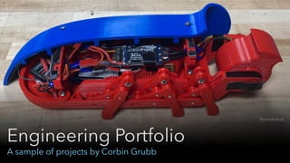
- 1. Engineering Portfolio A sample of projects by Corbin Grubb Stomatobot
- 2. Contents WPI Aerospace Engineering Major Qualifying Project • Lunar Micro Rover Autonomous Robots • Swanbot • Argus Remote Controlled Creations • Stomatobot • SkiBot
- 3. LUNAR MICRO ROVER WPI Aerospace Engineering Major Qualifying Project Design and analysis led by Corbin Grubb
- 4. PROJECT GOAL AND CONSTRAINTS ▸ Design a rover to explore the Lunar South Pole ▸ Build and test a prototype rover ▸ Rover must weigh less than 5 Kg ▸ Rover must carry a 2 Kg scienti fi c payload ▸ Rover must survive a 4-inch drop in earth gravity Rover during early testing
- 5. DESIGN PROCESS Several design options were considered to meet the project requirements, and two best design options were selected. Simple CAD models were created in SolidWorks to compare the weight, payload space, complexity, and obstacle clearing ability of each option. The four wheel rocker design was selected, and fi nal CAD designs were developed in SolidWorks, using of-the-shelf components whenever possible. ANSYS was then used to verify the strength of the design and to optimize the design wherever possible. Preliminary 2-Wheel Design Preliminary 4-Wheel Rocker Design
- 6. DESIGN FEATURES ▸ Chassis (1) holds the scienti fi c payload and control electronics ▸ Rockers (2) rotate freely relative to the chassis to overcome obstacles ▸ Motor gearboxes (3) provide power to each wheel individually ▸ Large wheels (4) provide traction in lunar regolith ▸ Differential Linkage (5) keeps chassis at the average angle of the two rockers Final SolidWorks Model (1) (2) (3) (4) (5)
- 7. STRUCTURAL ANALYSIS To ensure the design could survive a 4 inch drop, a simpli fi ed CAD model was created and ANSYS Explicit Dynamics was used to simulate the impact. The results from the Explicit Dynamics simulation were then used to develop ANSYS Static Structural simulations to test the fi nal CAD model ANSYS Static Structural simulation on fi nal design ANSYS Explicit Dynamics drop test with simpli fi ed CAD model
- 8. WHEEL DESIGN AND OPTIMIZATION The wheels of the rover were heavy and mission critical components, so extensive real-world and ANSYS tests were run to optimize the design. Real-world testing was performed to determine the shape of the traction fi ns. ANSYS simulations were run to determine the radial and tangential strength of the wheels using the data from the Explicit Dynamics drop test. Real-world traction testing Radial strength ANSYS test Tangential strength ANSYS test With each ANSYS simulation, the design of the wheel was adjusted to reduce weight. The fi nal design had a factor of safety of fi ve throughout most of the wheel.
- 9. ROVER TESTING The rover was tested climbing over a range of obstacles and terrains. The rover successfully overcame objects up to 150 mm high, equal to the diameter of the wheels. The rocker suspension system proved effective at reducing the motion of the chassis as the rover climbed uneven terrain. The wheel design demonstrated adequate grip in the simulated lunar regolith. Rover overcoming large obstacle
- 10. CREDITS MECHANICAL/ANALYSIS TEAM: Corbin Grubb Will Fisher Caleb Powell Marcela Mayor ELECTRICAL/CONTROLS TEAM: Travis McGregor Zachary Angell Lily Kinne David Acuna MISSION PLANNING: Watts Herideen-Woodruff ADVISOR: Professor Nikhil Karanjgaokar SPECIAL THANKS: WPI Academic Computing Lab WPI Practice Point Lab Daniel Ali Tribaldos
- 11. Swanbot Autonomous Panel Moving Robot Designed, simulated, and printed by Corbin Grubb Created for RBE 2001
- 12. Body Design Goals • Bot must be able to reach 4” by 4” by 1/4” panel at three unique heights and angles • Must only have one degree of freedom in upper linking • Must connect to Pololu Romi kit • Must have proper gear transmission, where needed input torque is less than 10% of motor stall torque • Minimal moving parts •
- 13. Gripper Design Goals • Must be able to hold and release a 4” by 4” by 1/4” stainless steel plate • Must need no input torque to maintain grip • Must require no more than 0.25 kg/cm of torque at any point • Must only have one degree of freedom • Minimal moving parts •
- 14. Body Features • Gripper ( 1 ) grabs and releases the target plate • Gear train ( 2 ) reduces input torque needed from blue motor ( 3 ) • Four-bar mechanism maneuvers gripper to the three required angles • Curved upper link and angled blue motor unintentionally gave robot a swanlike appearance ( 3 ) ( 1 ) ( 2 ) ( 4 )
- 15. Gripper Features • Lower plate ( 1 ) supports weight of the target plate • Compliant gripper “claw” ( 2 ) prevents plate tipping or sliding off lower plate • 9 Gram servo motor ( 3 ) actuates gripper • Two bearings in the rear ( 4 ) attach to rest of Swanbot ( 3 ) ( 1 ) ( 2 ) ( 4 )
- 16. Four-bar design To determine the proper four-bar mechanism, a sketch was made in Solidworks featuring the gripper in the three required positions. The mounting/pivoting points of the gripper were then used to f ind the necessary lengths for the “rocker” links and the location of the “ground” link.
- 17. Simulation of flexible gripper Color scale represents displacement Maximum force of 1 newton Compliant mechanism
- 18. Implementation • Compliant gripper part 3D printed in TPU plastic • Gripper body and servo lever printed in ABS plastic • 3 mm steel rods used as guide rails to prevent twisting • Base plate, body walls, gears, links, and spacers were 3d printed in ABS and PLA • M3 bolts were used as pins and axels • Ball bearings were press- f itted into the gears
- 19. Swanbot performing its duty Swanbot in action
- 20. Argus Autonomous Map Making Robot Sensor integration, Coding, and Testing by Corbin Grubb and Team 16 Created for RBE 2002
- 21. Mission Goals • Bot must be able to circumnavigate area autonomously • Must take measurements of internal object in two environments • Must convert distance measurements to an accurate maps of the objects • Must connect to Pololu Romi kit
- 22. Argus Features • Pololu Romi Chasis ( 1 ) for mobility, with a A - Star 32U4 board running C++ code • IR range sensor ( 2 ) for following the outer wall of the arena • Ultrasonic Sensor ( 3 ) for measuring distance to object • Esp32 Board ( 4 ) for uploading map to a server via WiFi • Argus’ name comes from additional cosmetic ultrasonic sensors ( 5 ), as Argus is a man with 100 eyes from greek mytholo g y ( 3 ) ( 1 ) ( 2 ) ( 4 ) ( 5 )
- 23. Mapping Process • Robot uses a State Machine to traverse the arena and collect data • Robot begins at a known location in the “idle” state, and begins when a button on the board is pressed • Robot begins crossing the arena using the IR sensor to follow the wall • At set distance intervals, the robot switches to a measurement state and collects 100 measurements of the object to be averaged and used to f ill one cell in a matrix • The robot repeats this process until it reaches the far wall, then it moves to the other side of the arena • The measuring process is repeated in the opposite direction
- 24. Results • Argus successfully mapped the objects in both arenas • Robot retuned within 10 cm of original spot • Both matrices were uploaded to a web server live Example of a matrix. 1s represent blocks mapped during the f irst pass, 2s represent blocks mapped during the second pass, and 3s represent blocks mapped during both passes
- 25. Stomatobot V0 Ant-Weight Combat Robot Designed, built, and driven by Corbin Grubb, As a part of the WPI Robotics Club
- 26. Inspired by Mantis Shrimp (Stomatopods), Stomatobot V0 served as a functional prototype for future ant-weight combat robots. Stomatobot V0 featured six klann mechanism legs, and a hard shell supported by stiff plastic springs. An asymmetrical vertical spinner was used for the active weapon. The robot was designed in Fusion 360.
- 27. For using legs instead of wheels, the bot was granted a weight limit of two pounds, twice the limit for wheeled bots. All parts for Stomatobot V0 were 3D printed, with screws, bearings, and electronics as exceptions. The bot used a 3-cell LiPo battery, two brushed drive motors, and a brushless weapon motor, with a receiver and two ESCs to control the bot.
- 28. As an experimental prototype, Stomatobot V0 only won one of its fi ve fi ghts, but sustained little damage. The fi ghts proved the resilience of the shell, but the bot lacked maneuverability. Several design changes are being implemented in Stomatobot V1, as well as a “Club” weapon. Stomatobot V0 with minor damage to the shell and weapon, and a broken weapon mount
- 29. SkiBot Radio Controlled Skiing Robot Designed, built, programmed, and tested by Corbin Grubb Cosmetic cover made by Nate Stote and Corbin Grubb
- 30. • Mimic the motion of human skiing • Have all electronics contained within rectangular body • Be capable of propulsion and steering • Be remote controlled • Look like a certain cartoon robot Design Goals
- 31. • An Arduino Uno ( 1 ) receives signals from a radio receiver board • Arduino drives a brushed motor ( 2 ) through a PWM driver board • Motor drives a ~15:1 gearbox that in turn drives the Klann mechanism arms ( 3 ) • Servo motor changes the relative height of the legs to tilt robot and steer ( 4 ) SkiBot Features ( 1 ) ( 2 ) ( 4 ) ( 3 )
- 32. Finished Robot