1. GSPublisherEngine 33.68.94.84
INDEX OF SHEETS
A-001
A-101
A-102
A-201
A-202
S-301
S-302
D-101
E-101
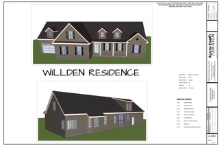
COVER SHEET
MAIN FLOOR
SECOND FLOOR
W&E ELEVATIONS
N&S ELEVATIONS
FOUNDATION
FIRST FLOOR FRAMING
DETAILS
ELECTRICIAN MARKUP PLAN
LOCATION: Madison County, ID
SNOW LOAD: 35 lbs
WIND SPEED: 90 mph
FROST DEPTH: 36"
SEISMIC: D1
REGULATION: 2009 IBC
WILLDEN RESIDENCE
DESCRIPTION
PROJECTNO:
DRAWNBY:
CHK'DBY:
REVISIONDATE
SHEET 1
OF 9
A-001
PLOTDATE:
COVERSHEETSHEETTITLE:
CalebWillden
10/11/2014
1066NorthYellowstoneHwy
Rexburg,ID83440
www.southforkengineering.com
327HarvardAvenue
RexburgIdaho
83440US
Copyright2014|SouthforkEngineering|AllRightsReserved.
SouthForkDesignGroup,LLC
THESE PLANS ARE NOT DESIGNED FOR A SPECIFIC LOCATION.
BUILDER/OWNER ARE ADVISED TO OBTAIN ENGINEERING
FOR THE SPECIFIC LOCATION.
2. GSPublisherEngine 33.68.94.84
RG
FF
BB
G
6
J
K
H
B B
3
BB
9
10
2
1
1
1
1
1
1
1
1
B
1
1
2
I
I
14
7DR W
19'-7 1/2" 23'
80'-3 1/2"
2'-93/4"8'-1/2"2'-1/4"8'-71/2"11'-83/4"8'-71/2"2'
12'-101/2"29'2'
43'-101/2"
18'-6 1/4" 1'-11 3/4" 5'-11 1/2" 9'-3 1/4" 6'-9" 9'-11 1/2" 2'-3 3/4" 2'-2 1/2" 1' 1' 3'-2" 3'-2" 1' 1'
1'-9 1/2"
4'-4 1/2" 3'-4" 3'-6"
20'-6" 34'-3" 2'-2 1/2" 2' 6'-4" 2'1'-9 1/2" 4'-4 1/2" 6'-10"
8'-101/2"2'-6"2'2'-41/2"7'-4"10'-1"10'-81/2"
8'-101/2"10'-81/2"2'-41/2"7'-4"12'-7"2'
43'-101/2"
80'-3 1/2"
1'-9 1/2" 16'-1/2" 1'-9 1/4" 6'-4" 10'-4" 6'-4" 3' 1'-11 3/4" 6'-1/4" 6'-6 3/4" 2'-8 1/2" 5'-1/2" 12'-4 1/2"
12'-4 1/2"4'-11 3/4" 12'-6 3/4" 7'-9"
7'-4 1/2"
12'-101/2"
3'-1/2" 7'-4" 6'-3 1/2" 5'
4'-81/2"7'-6"16'-91/2"
5'-8" 4'-9" 9'-11"
6'-9 1/4" 1'-1 1/4" 11'-5 3/4" 5'-6 1/2" 3'-4 1/2"
9'-31/4"93/4"
5'5'
8'-11"
7'-6"
1'-73/4"
5'-4"
8'-8 1/2"2'-1/2"
3'-4 1/2"
8'-7"5'-61/2"
14'-11/2"
14'-6 1/2"
4'
3'-81/2"
10'-9"
7'-41/2"
2'
1
#DrgID
#LayID
8' ARCHWAY
BEDROOM #2
MASTER BEDROOM
BATH
SHOWER
MASTER BATH
DOUBLE GARAGE
COVERED PORCH
LAUNDRY
W.I.C.PANTRY
FAMILY ROOM
ENTRY
LIVING ROOM
MUD ROOM
CLOSET
DINING ROOM
DOUBLE GARAGE
12'-2 1/2" X 10'-0"
5'-2" X 4'-7 1/2"
8'-6 1/2" X 5'-0"
10'-4 1/2" X 10'-2"
8'-3 1/2" X 6'-11 1/2"
10'-4 1/2" X 11'-9"
13'-11 1/2" X 13'-9"14'-6" X 14'-1 1/2"
6'-1/2" X 7'-0"
7'-0" X 7'-0"
HALF
BATH
2'-6" X
7'-0"
8'-11 1/2" X 15'-11"
KITCHEN
10'-3" X 15'-11"
19'-11 1/2" X 28'-0"
22'-0" X 17'-1/2"
FIREPLACE
FOLDING COUNTER &
UPPER CABINETS
BENCH
2
UP
16 x 7 1/2" = 10'-1 3/4"
1
2
3
4
5
6
7
8
9
10
11
12
13
14
15
DOOR SCHEDULE
ID
1
2
3
4
6
7
9
10
Quantity
19
2
1
1
1
4
1
1
DOOR
W
2'-6"
3'
3'
4'
6'
5'
8'
16'
HT
6'-8"
6'-8"
8'
6'-8"
8'
6'-8"
8'
8'
3D View NOTES
WINDOW SCHEDULE
ID
A
B
C
D
E
F
G
H
I
J
K
Quantity
1
7
1
2
5
2
1
1
2
1
1
SIZE
WIDTH
3'
3'
4'
3'
2'-6"
4'
2'-6"
3'
2'
4'
5'
HEIGHT
5'-6"
6'-4"
5'-4"
5'-4"
4'
5'-4"
4'-4"
4'-4"
6'-4"
6'-4"
4'-4"
3D Front Axonometry NOTES
0 2' 4' 8'SCALE: 1/4" = 1'-0"1
MAIN LEVEL PLAN
DESCRIPTION
PROJECTNO:
DRAWNBY:
CHK'DBY:
REVISIONDATE
SHEET 2
OF 9
A-101
PLOTDATE:
MAINFLOORSHEETTITLE:
CalebWillden
10/11/2014
1066NorthYellowstoneHwy
Rexburg,ID83440
www.southforkengineering.com
327HarvardAvenue
RexburgIdaho
83440US
Copyright2014|SouthforkEngineering|AllRightsReserved.
SouthForkDesignGroup,LLC
THESE PLANS ARE NOT DESIGNED FOR A SPECIFIC LOCATION.
BUILDER/OWNER ARE ADVISED TO OBTAIN ENGINEERING
FOR THE SPECIFIC LOCATION.
3. GSPublisherEngine 33.68.94.84
E EE
1 1
1 1
1
EE
C
A
1
7
1
77
1
DD
12'-101/2"5'-8"2'-91/2"12'-1"2'-6"5'-111/2"
12'-101/2"5'-8"17'-41/2"5'-111/2"
41'-101/2"
7'-2 1/2" 2'-5 1/2" 2'-5 1/2" 7'-1 3/4" 4'-11" 6'-11 1/4" 6'-8 1/4" 4'-5 1/2" 5'-4" 2'-5 1/2" 2'-5 1/2" 5'-9 1/4" 2'-6 1/4" 2'-4 3/4" 2'-2 1/2" 14'-6 1/4"
7'-2 1/2" 4'-11" 7'-1 3/4" 4'-6 3/4" 13'-7 1/2" 4'-9 3/4" 10'-3" 5'-9 1/4" 4'-11" 16'-8 3/4"
80'-3 1/2"
8'-101/2"9'-8"8'-10"5'-51/2"3'-1"5'-111/2"
8'-11"9'-8"17'-41/2"5'-111/2"
41'-101/2"
5'-21/2"
5'-21/2"
5'-21/2"
12'-7"
3'-10 1/2"
10'-9"
14'-7"
3'-10 1/2" 14'-10 1/2" 2'-4 1/2" 6'-11 1/2"
7'-41/2"
5'-41/2"5'-41/2"
3'-1/2"
20'-6 1/2" 8'-11" 50'-10"
20'-6 1/2" 2'-6 1/4" 3'-10" 2'-6 1/2" 50'-10"
CUSTOM
DOOR TO
ATTIC
CUSTOM
DOOR TO
ATTIC
36'-9 1/2" X 17'-0"
BONUS ROOM
14'-6" X 10'-4 1/2"
BEDROOM #2
14'-1/2" X 13'-11"
BEDROOM #3
6'-7" X 10'-4 1/2"
BATH #2
13'-3" X 12'-6"
BEDROOM #4
UP
16x71/2"=10'-13/4"
1
2
3
4
5
6
7
8
9
10
11
12
13
14
15
0 2' 4' 8'SCALE: 1/4" = 1'-0"1
SECOND FLOOR
DESCRIPTION
PROJECTNO:
DRAWNBY:
CHK'DBY:
REVISIONDATE
SHEET 3
OF 9
A-102
PLOTDATE:
SECONDFLOORSHEETTITLE:
CalebWillden
10/11/2014
1066NorthYellowstoneHwy
Rexburg,ID83440
www.southforkengineering.com
327HarvardAvenue
RexburgIdaho
83440US
Copyright2014|SouthforkEngineering|AllRightsReserved.
SouthForkDesignGroup,LLC
THESE PLANS ARE NOT DESIGNED FOR A SPECIFIC LOCATION.
BUILDER/OWNER ARE ADVISED TO OBTAIN ENGINEERING
FOR THE SPECIFIC LOCATION.
4. GSPublisherEngine 33.68.94.84
Footers Below Local Frost
Stone Veneer
Steps to Grade as necessary
36" Guard Rail
Wrapped
Column
Verify Wall Finishes
w/Owner
MAIN FLOOR
±0'
TOP PLATE
±9'-0"
TOP OF FOOTER
±5'-2"
MAIN FLOOR
±0'
TOP PLATE
±9'-0"
TOP OF FOOTER
±5'-2"
12
10
10
12
10
12
10
12
12
12
TOP OF ROOF LINE
±22'-11 1/2"
TOP OF ROOF LINE
±22'-11 1/2"
0 2' 4' 8'SCALE: 1/4" = 1'-0"2
REAR ELEVATION
0 2' 4' 8'SCALE: 1/4" = 1'-0"1
FRONT ELEVATION
DESCRIPTION
PROJECTNO:
DRAWNBY:
CHK'DBY:
REVISIONDATE
SHEET 4
OF 9
A-201
PLOTDATE:
W&EELEVATIONSSHEETTITLE:
CalebWillden
10/11/2014
1066NorthYellowstoneHwy
Rexburg,ID83440
www.southforkengineering.com
327HarvardAvenue
RexburgIdaho
83440US
Copyright2014|SouthforkEngineering|AllRightsReserved.
SouthForkDesignGroup,LLC
THESE PLANS ARE NOT DESIGNED FOR A SPECIFIC LOCATION.
BUILDER/OWNER ARE ADVISED TO OBTAIN ENGINEERING
FOR THE SPECIFIC LOCATION.
5. GSPublisherEngine 33.68.94.84
12
10
TOP OF GABLE ROOF LINE
±22'-6 1/2"
TOP OF GABLE ROOF LINE
TOP OF DORMER ROOF LINE
±18'-10 1/2"
TOP OF DORMER ROOF LINE
TOP OF GABLE ROOF LINE
±16'-1/2"
TOP OF GABLE ROOF LINE
10
12
12
10
12
10
1010
12
-0 3/4"
10'-3/4"
15'-1 3/4"
18'-2 1/4"
Footers Below
Local Frost (typ)
Anchor Stem Wall to
Footer
TJI Floor System
Attic Truss Floor
Attic Truss
KitchenStorage
AtticAttic
Garage
0 2' 4' 8'SCALE: 1/4" = 1'-0"1
RIGHT ELEVATION
0 2' 4' 8'SCALE: 1/4" = 1'-0"2
LEFT ELEVATION
0 2' 4' 8'SCALE: 1/4" = 1'-0"S2
SECTION @ STAIR
DESCRIPTION
PROJECTNO:
DRAWNBY:
CHK'DBY:
REVISIONDATE
SHEET 5
OF 9
A-202
PLOTDATE:
N&SELEVATIONSSHEETTITLE:
CalebWillden
10/11/2014
1066NorthYellowstoneHwy
Rexburg,ID83440
www.southforkengineering.com
327HarvardAvenue
RexburgIdaho
83440US
Copyright2014|SouthforkEngineering|AllRightsReserved.
SouthForkDesignGroup,LLC
THESE PLANS ARE NOT DESIGNED FOR A SPECIFIC LOCATION.
BUILDER/OWNER ARE ADVISED TO OBTAIN ENGINEERING
FOR THE SPECIFIC LOCATION.
6. GSPublisherEngine 33.68.94.84
20'-6" 59'-9 1/2"
19'-7 1/2" 23' 25'-3 1/2" 12'-4 1/2"
8'-101/2"33'
12'-101/2"29'
80'-3 1/2"
41'-101/2"
80'-3 1/2"
41'-101/2"
23'-71/2"
16'-8" 4'-9 1/2"
12'-21/2"4'-81/2"
16'-11"
4'-81/2"
9'-2"13'-91/2"
22'-111/2"
27'-8"
13'-101/2"13'-91/2"
4'
17'-101/2"13'-91/2"
16'-8" 30'-9" 11'-1/2"
Holdowns per engineer Holdowns per engineer
Holdowns per engineer
Holdowns per engineer
Holdowns per engineer
Holdowns per engineer
Holdowns per engineer
Holdowns per engineer
Holdowns per engineer Holdowns per engineer
Holdowns per engineer
Holdowns per engineer
Holdowns per engineer
Depress foundation wall to top
of finished slab.
Depress foundation wall to top
of finished slab.
Post Base Post Base Post Base
Depress foundation wall to top
of finished slab.
6" Porch Cap over compacted fill. Rebar Mat per Engineer
Craw Space Note:
1. Foundation wall size by engineer, Rebar per 2009 IBC or local
code.
2. Continuous footings sized by engineer with continuous rebar,
and are to be below local frost.
3. Anchor/Holdown size and location by engineer or local code.
4. 4" crush cravel over vapor barior.
5. Crawl space ventalation per local code.
6. Pressure treated seal at perimeter of foundation.
7. Crawl space access owner/builder.
0 2' 4' 8'SCALE: 1/4" = 1'-0"1
FOUNDATION PLAN
DESCRIPTION
PROJECTNO:
DRAWNBY:
CHK'DBY:
REVISIONDATE
SHEET 6
OF 9
S-301
PLOTDATE:
FOUNDATIONSHEETTITLE:
CalebWillden
10/11/2014
1066NorthYellowstoneHwy
Rexburg,ID83440
www.southforkengineering.com
327HarvardAvenue
RexburgIdaho
83440US
Copyright2014|SouthforkEngineering|AllRightsReserved.
SouthForkDesignGroup,LLC
THESE PLANS ARE NOT DESIGNED FOR A SPECIFIC LOCATION.
BUILDER/OWNER ARE ADVISED TO OBTAIN ENGINEERING
FOR THE SPECIFIC LOCATION.
7. GSPublisherEngine 33.68.94.84
24'-31/2"
4'4'-81/2"9'-9"14'-61/2"
16'-8" 30'-9" 12'-4 1/2"
59'-9 1/2"
33'
18'-51/2"14'-61/2"
36'-5 1/2" 2' 6'-4" 2' 13'
59'-9 1/2"
1'-2 3/4" 1'-4"
1'-4" 1'-2 3/4"
Floor joist sizing and type per engineer over
pressure treated seal plate.
3/4" T&G OSB w/ glue and fasten per
manufacturers rec. Crawl space access per
owner builder.
Wood I Joists @ 16" o.c.
Wood I Joists @ 16" o.c.
10/12
10/12
10/12
10/12
10/12
10/12
10/12 10/12 10/12 10/12 10/12 10/12
10/12 10/12
12/12 12/12
3/12
3/12
3/12
0 2' 4' 8'SCALE: 1/4" = 1'-0"1
FIRST FLOOR FRAMING
0 2' 4' 8'SCALE: 1/4" = 1'-0"2
ROOF LAYOUT
DESCRIPTION
PROJECTNO:
DRAWNBY:
CHK'DBY:
REVISIONDATE
SHEET 7
OF 9
S-302
PLOTDATE:
FIRSTFLOORFRAMINGSHEETTITLE:
CalebWillden
10/11/2014
1066NorthYellowstoneHwy
Rexburg,ID83440
www.southforkengineering.com
327HarvardAvenue
RexburgIdaho
83440US
Copyright2014|SouthforkEngineering|AllRightsReserved.
SouthForkDesignGroup,LLC
THESE PLANS ARE NOT DESIGNED FOR A SPECIFIC LOCATION.
BUILDER/OWNER ARE ADVISED TO OBTAIN ENGINEERING
FOR THE SPECIFIC LOCATION.
8. GSPublisherEngine 33.68.94.84
DESCRIPTION
PROJECTNO:
DRAWNBY:
CHK'DBY:
REVISIONDATE
SHEET 8
OF 9
D-101
PLOTDATE:
DETAILSSHEETTITLE:
CalebWillden
10/11/2014
1066NorthYellowstoneHwy
Rexburg,ID83440
www.southforkengineering.com
#ClientCompany
327HarvardAvenue
RexburgIdaho83440
US
Rexburg,US83440Copyright2014|SouthforkEngineering|AllRightsReserved.
SouthForkDesignGroup,LLC
GENERAL NOTES
All work shall be consistent with the best practices of the trades involved
and conform to the 2009 IRC.
Owner/Contractor or sub-contractor shall verify plans, dimensions and any
work or construction.
Any footing or foundation re-design shall be performed by a registered
professional engineer.
Roof truss and/or beam manufacturer shall provide shop drawings showing
recommended design. Design loads per applicable local codes and
connection details signed and sealed by a registered professional engineer.
Forced air heating. All ductwork shall be located above basement ceiling
line whenever possible.
Size main hvac trunk-line to allow a 7’-0” minimum finish ceiling in
basement areas ducts pass through per IRC R305.
Furnace shall not be used prior to completion of house unless approved by
owner. Owner/Contractor shall assure that all duct registers and furnace
are clean and free of construction materials.
Provide waterproof sheetrock in tub, shower and laundry areas per IRC
R307.2.
Vent dryer and bathroom exhaust fans to exterior of house per IRC R303.3.
Case and jamb all finished door openings.
Interior and/or exterior railings required at porch or landing will conform to
IRC R312.
Engineered joist floor systems shall be installed per manufacturer
specifications.
Provide proper gutter systems over all walks, driveways, porches or decks
as indicated on plans.
Install 6” of clean gravel in all window wells.
Finish grade the lot to slope a minimum of 6” in the first 10 feet away from
the foundation, then minimum 2% thereafter per IRC R401.3.
Mix, place, consolidate and cure all concrete per IRC R403 & R404.
All smoke detectors shall be 110V main power with battery backup. All
detectors to be connected for simultaneous alarm. Smoke alarms per IRC
R313.
Dimensions are to framed walls without sheetrock unless specified
otherwise.
FOUNDATION NOTES
All footings shall bear on undisturbed soil or compacted fill capable of
supporting a minimum design bearing pressure of 1500 PSF.
Footing elevations shown on the foundation plan, shall be lowered as
required to obtain the required design bearing pressure.
Unless noted otherwise, the bottom of all exterior footings shall be placed 6"
below local frost depth: the bottom of all interior footings shall be placed 12"
minimum below interior finished grade.
Concrete foundation shall be cast in accordance with the requirements of
IRC Section R402.
Slab on grade construction shall be in accordance with IRC R506.
STRUCTURAL NOTES
The structural drawing shall be used in conjunction with the drawings of all
other disciplines and the project specifications. The contractor shall verify
the requirements of the other trades as to sleeves, chases, hangers,
inserts, anchors, holes and other items to be placed or set in the structural
work.
The Owner/Contractor shall be responsible for complying with all safety
precautions and regulations during the work. The engineer will not advise
on nor issue direction as to safety precautions and programs.
The structural drawings herein represent the finished structure. The
Owner/Contractor shall provide all temporary guying and bracing required to
erect and hold the structure in proper alignment until all structural work and
connections have been completed. The investigation, design, safety,
adequacy and inspection of erection bracing, shoring, temporary supports,
etc. are the sole responsibility of the Owner/Contractor.
The engineer shall not be responsible for the methods, techniques and
sequences of procedures to perform the work. The supervision of the work
is the sole responsibility of the Owner/Contractor.
Drawings indicate general and typical details of construction. Where
conditions are not specifically shown, similar details of construction shall be
used, subject to approval by the engineer.
Loading applied to the structure during the process of construction shall not
exceed the safe load-carrying capacity of the structural members. Do not
apply any construction loads until structural framing is properly connected
together and until all temporary bracing is in place.
All ASTM and other references are per the latest additions of the standards,
unless otherwise noted.
WOOD FRAMING NOTES
All wood framing material shall be surfaced dry and used at 19% maximum
moisture content.
All stud and wall framing shall be No. 2 grade Doug Fir.
All joist, rafter, & misc. framing shall be No. 2 grade Doug Fir. Unless noted
otherwise.
All framing exposed to the weather or in contact with masonry or concrete
shall be pressure treated in accordance with the American Wood Preservers
Association Specification where possible.
Provide LVL header beams of the same size as joists or rafters to frame
around openings in the plywood deck unless otherwise indicated.
Bolt-holes shall be carefully centered and drilled not more than 1/16” larger
than the bolt diameter. Bolted connections shall be snug but not to the
extent of crushing wood under washers.
Prefabricated metal joist hangers, hurricane clips, hold-down anchors and
other accessories shall be as manufactured by "Simpson Strong-Tie
Company”, or approved equal. Install all accessories per the manufacturer’s
requirements. All steel shall have a minimum thickness of 0.04 inches (per
ASTM A446, Grade A) and be galvanized (coating G60).
Holes and notches drilled or cut into wood framing shall not exceed the
requirements of IRC R600.
All plates, anchors, nails, bolts, washers and other miscellaneous hardware
permanently exposed to weather shall be hot dip galvanized.
Sheathing of floors, walls and roofs shall be in accordance with IRC R500,
R600 and R800.
2'-6"MIN
7
34
8
2
1
9
13 12
11
9
10
6
5
6"MIN
KEYNOTES
1 - FOOTING, SEE PLAN AND SCHEDULE FOR
SIZE AND REINF.
2 - CONCRETE WALL
3 - FLOOR JOIST, SEE PLAN
4 - CONT. SILL PLATE AND ANCHOR BOLTS
5 - FLOOR SHEATHING
6 - REQ'D PANEL BOUNDARY NAILING
7 - WALL STUDS
8 - WALL SHEATHING
9 - REQ'D PANEL EDGE NAILING
10 - CONT. BOTTOM PLATE W/ 10d COMMON
NAILS @ 6" O.C.
11 - CONT. RIMBOARD W/ SIMPSON A35 CLIP @
32" O.C.
12 - 2x8 LEDGER W/ 1/2 DIA LAG SCREWS @ 12"
O.C., STAGGER TOP & BOT.
13 - DECK JOIST
2
1
3
1 3
7
6
3
4
5
1
3
8
4
2
1
2
E
D
PLAN
KEYNOTES
1 - WALL SHEATHING
2 - HOLDOWN
3 - WOOD STUD WALL
4 - CONCRETE WALL
5 - WOOD ATTACHMENT SEE HOLDOWN
CONNECTION SCHEDULE
6 - EDGE NAILING SEE SHEAR WALL
SCHEDULE
7 - WOOD POST SEE HOLDOWN SCHEDULE
8 - WOOD FLOOR JOIST
SECTION D
SECTION E
2'-6"MIN
7
34
8
2
1
9
3 14
11
9
10
6
5
6"MIN
12
13
KEYNOTES
1 - FOOTING, SEE PLAN AND SCHEDULE FOR
SIZE AND REINF.
2 - CONCRETE WALL
3 - FLOOR JOIST, SEE PLAN
4 - CONT. SILL PLATE AND ANCHOR BOLTS
5 - FLOOR SHEATHING
6 - REQ'D PANEL BOUNDARY NAILING
7 - WALL STUDS
8 - WALL SHEATHING
9 - REQ'D PANEL EDGE NAILING
10 - CONT. BOTTOM PLATE W/ 10d COMMON
NAILS @ 6" O.C.
11 - CONT. RIMBOARD W/ SIMPSON A35 CLIP @
32" O.C.
12 - JOIST BLOCKING @ 32" O.C. W/ SIMPSON H3
(PROVIDE WEB FILLER AS REQ'D
13 - (4) 10d COMMON @ EACH BLOCK
14- 2x8 LEDGER W/ 1/2" DIA LAG SCREWS @ 12"
O.C., STAGGER TOP & BOT.
3
4
2
1
KEYNOTES
1 - POST, SEE PLAN
2 - SIMPSON POST BASE
3 - PIER W/ (4) #4 DOWELS
INTO FOOTING & #3 CLOSED STIRRUPS @
12" O.C. W/ (3) STIRRUPS IN TOP 9"
4 - CONC. FOOTING, SEE SCHEDULE
2
1
7
6
5
3
4
KEYNOTES
1 - FOOTING, SEE PLAN AND SCHEDULE FOR
SIZE AND REINF.
2 - CONCRETE WALL
3 - CONCRETE SLAB
4 - CONT. SILL PLATE AND ANCHOR BOLTS
5 - WALL STUDS
6 - WALL SHEATHING
7 - REQ'D PANEL EDGE NAILING
Dormer Ridge
Dormer
Rafter
Simpson Hangers
Simpson VPA
Valley Rafter
Not Necessary if Front
of Dormer Aligns With
Load-Bearing Wall Below
Simpson Strap
Support
Rafter Beams
9
104
6
6
8
6
7
2
1
11
12
5
3
KEYNOTES
1 - FLOOR SHEATHING
2 - REQ'D PANEL BOUNDARY NAILING
3 - WALL STUDS
4 - DOUBLE TOP PLATE
5 - WALL SHEATHING
6 - REQ'D PANEL EDGE NAILING
7 - CONT. BOTTOM PLATE W/ 10d COMMON
NAILS @ 6" O.C.
8 - CONT. RIMBOARD W/SIMPSON A35 CLIP
@ 32" O.C.
9 - SOLID BLOCKING
10 - FLOOR JOISTS
11 - JOIST BLOCKING @ 32" O.C. W/ SIMPSON
H3 (PROVIDE WEB FILLER AS REQ'D)
12 - (4) 10d COMMON @ EACH BLOCK
7
10
3
9
8
5
11
1 62
3
4
KEYNOTES
1 - 10d COMMON @ 6" O.C.
2 - FLOOR SHEATHING
3 - STUD WALL W/ 2X6 @ 16" O.C.
4 - BLOCKING W/ 10d COMMON @ 6" O.C.
5 - FLOOR JOISTS
6 - WEB SSTIFFENERS EACH SIDE
7 - PROVIDE MID HEIGHT BLOCKING
8 - FOOTING
9 - SHEATHING TO MATCH WALL ABOVE
10 - L50 EACH BLOCK
11 - SIMPSON SDS25300
NOTES:
A - LOAD BEARING WALL ABOVE MUST
STACK DIRECTLY OVER WALL BELOW
86
7
2
1
3
9
5
4
KEYNOTES
1 - FLOOR SHEATHING
2 - REQ'D PANEL BOUNDARY NAILING
3 - WALL STUDS
4 - DOUBLE TOP PLATE
5 - WALL SHEATHING
6 - REQ'D PANEL EDGE NAILING
7 - CONT. RIMBOARD W/SIMPSON A35 CLIP
@ 32" O.C.
8 - FLOOR JOIST, W/ SIMPSON H3 AT 32" O.C.
MAX (PROVIDE WEB FILLER AS REQ'D)
9 - PARTITION WALL ABOVE WHERE OCCURS,
COORDINATE WITH ARCH.
6
6
6
6
1
48
1
7
2
13
3 4
5
3
1
32
4
5
KEYNOTES
1 - EDGE NAILING PER SHEAR WALL
SCHEDULE.
2 - WALL SHEATHING AS OCCURS.
3 - LOCATION OF STRAP AT END OF SHEAR
WALL, SEE PLAN FOR TYPE OF STRAP.
4 - FULL HEIGHT WOOD STUD TYP.
5 - 16d FACE NAIL AT 16" O.C.
6 - DISTANCE FROM CORNERS TO CENTER OF
STRAP EQUALS WIDTH OF WALL (MAX.)
7 - 16d FACE NAIL AT 6" O.C.
EXTERIOR SHEATHING AT CORNER
INTERIOR SHEATHING AT CORNER
INTERIOR SHEATHING AT
WALL INTERSECTION
3
5
6
2
4
1
2 1
8
3
5
6
7
KEYNOTES
1 - FLOOR SHEATHING
2 - REQ'D PANEL BOUNDARY NAILING
3 - FLOOR JOISTS
4 - SIMPSON JOIST HANGER
5 - WOOD BEAM
6 - BUILT UP BEAM NAILING
7 - BLOCKING W/ 10d TOE NAILS AT 6" O.C.
TO BEAM BELOW (AT SIM. CONDITIONS
WHERE JOISTS END AT BEAM, USE CONT.
RIM JOISTS IN LIEU OF THE BLOCKING)
8 - SIMPSON H3 AT 32" O.C. MAX. PROVIDE
WEB FILLER AS REQ'D)
CASE A
7
8
4
6
5312
1 2
4 91110
8
6
KEYNOTES
1 - (4) 16d NAILS INTO EACH ROOF FRAMING
MEMBER
2 - 2x8 (MIN) CONT BEARING PLATE.
3 - TOE NAIL OVER-BUILD FRAMING TO
BEARING PLATE W/ (3) 16d NAILS MIN.
4 - ROOF SHEATHING
5 - 2x OVERBUILD FRAMING
6 - TOP CHORD OF TRUSS OR ROOF
FRAMING MEMBER
7 - 2x STUD PONY WALL AS OCCURS ON
PLAN (WALL SHALL BE CENTERED
BETWEEN MAX SPAN), ALIGN OVER
TRUSS PANEL POINT.
8 - ROOF SHEATHING (SHEATH LOWER
ROOF PRIOR TO CONSTRUCTION OF
OVER-BUILD).
9 - PREFABRICATED OVERBUILD ROOF
TRUSSES @ 24" O.C.
10 - (3) 16d NAILS INTO EACH ROOF FRAMING
MEMBER.
11 - 2x6 (MIN) CONT BEARING PLATE.
12 - EDGE NAILING 8d NAILS AT 4" O.C.
OPTION 1
OPTION 2
8
732" TYP. WITH
SOLID BLOCKING
10
3 9
12
3
4
6
5
3
KEYNOTES
1 - HEADER BEARING TRIMMERS OR HEADERS
2 - FULL HEIGHT STUD FLOOR TO FLOOR
3 - A.P.A. RATED WALL SHEATHING
4 - REQ'D PANEL EDGE NAILING
5 - COIL STRAP
6 - 2x FLAT BLOCKING
7 - HEADER AT DOOR OR WINDOW, TYP.
8 - CEILING OR FLOOR LINE
9 - FLOOR LINE
10 - SIMPSON CS16 COILED STRAP CUT TO
FIT EACH OPENING TOP AND BOTTOM
(TOP ONLY AT DOORS) FILL EVERY
OTHER NAIL HOLE WITH 8d COMMON
NAILS
TYP. DOOR
OPENING
TYP. WINDOW
OPENING
B
B
A
SECTION A
SECTION B
NOT TO SCALE
FLOOR JOIST TO CONCRETE WALL
NOT TO SCALE
TYPICAL STHD HOLDOWN
NOT TO SCALE
FLOOR JOIST BLOCKING
NOT TO SCALE
CONCRETE PIER
NOT TO SCALE
STUD WALL TO CONCRETE WALL CONNECTION
NOT TO SCALE
DORMER DETAIL
NOT TO SCALE
FLOOR JOISTS TO STUD WALL
NOT TO SCALE
DETAIL
NOT TO SCALE
FLOOR JOIST INT. SHEAR WALL
NOT TO SCALE
TYPICAL SHEAR SHEATHING AT WALL INTERSECTION
NOT TO SCALE
JOIST @ BEAM CONNECTION
NOT TO SCALE
TYPICAL OVERBUILD FRAMING
NOT TO SCALE
LATERAL TIES AT OPENINGS
9. GSPublisherEngine 33.68.94.84
RG
FF
BB
G
6
J
K
H
B B
3
BB
9
10
2
1
1
1
1
1
1
1
1
B
1
1
2
I
I
14
7DR W
UP
16 x 7 1/2" = 10'-1 3/4"
1
2
3
4
5
6
7
8
9
10
11
12
13
14
15
E EE
1 1
1 1
1
EE
C
A
1
7
1
77
1
DD
UP
16x71/2"=10'-13/4"
1
2
3
4
5
6
7
8
9
10
11
12
13
14
15
0 2' 4' 8'SCALE: 1/4" = 1'-0"1
Main Level Electrical
0 2' 4' 8'SCALE: 1/4" = 1'-0"2
Upper Level Electrical
DESCRIPTION
PROJECTNO:
DRAWNBY:
CHK'DBY:
REVISIONDATE
SHEET 9
OF 9
E-101
PLOTDATE:
ELECTRICIANMARKUPPLANSHEETTITLE:
CalebWillden
10/11/2014
1066NorthYellowstoneHwy
Rexburg,ID83440
www.southforkengineering.com
327HarvardAvenue
RexburgIdaho
83440US
Copyright2014|SouthforkEngineering|AllRightsReserved.
SouthForkDesignGroup,LLC
THESE PLANS ARE NOT DESIGNED FOR A SPECIFIC LOCATION.
BUILDER/OWNER ARE ADVISED TO OBTAIN ENGINEERING
FOR THE SPECIFIC LOCATION.