
Recommended
Recommended
More Related Content
What's hot
What's hot (20)
Viewers also liked
Viewers also liked (16)
Similar to Introduction to AFM
Similar to Introduction to AFM (20)
Recently uploaded
Recently uploaded (20)
Introduction to AFM
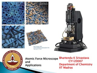
- 1. Atomic Force Microscope and Applications Bhartendu K Srivastava CY12D007 Department of Chemistry IIT Madras
- 2. PRINCIPLE • Invented in 1986 • Cantilever • Tip • Surface • Laser • Multi-segment photo detector
- 4. Topography Contact Mode ◦ High resolution ◦ Damage to sample ◦ Can measure frictional forces Non-Contact Mode ◦ Lower resolution ◦ No damage to sample Tapping Mode ◦ Better resolution ◦ Minimal damage to sample 2.5 x 2.5 nm simultaneous topographic and friction image of highly oriented pyrolytic graphic (HOPG). The bumps represent the topographic atomic corrugation, while the coloring reflects the lateral forces on the tip. The scan direction was right to left http://stm2.nrl.navy.mil/how-afm/howafm.html#imaging%20modes
- 7. With an AFM, a large range of topographies and many types of materials can be imaged. Examples of surface features that may be imaged include: atomic terraces, carbon nanotubes, colloidal particles, viruses, DVD textures up to micro lens textures, fractured surfaces, and complex multi-phase polymers. In other words, AFM is capable of delivering unique 3D topography information from the angstrom level to the micron scale with unprecedented resolution. Sample preparation
- 8. The following is a partial list of the material classes of particles in different environmental media, as analyzed by an AFM: 1.0 Imaging in Air 2.0 Imaging in liquids 3.0 Imaging embedded particles 1.1 Dry Powders 2.1 Bio-Particles in 3.1 Soft polymer and Bio buffer materials 1.2 Evaporated 2.2 Inorganic Particles 3.2 Hard Surface Material Suspensions 1.3 Bio-Particles 3.3 Membranes and defects 1.4 Carbon nanotubes 1.5 TEM Samples 1.6 SEM Samples
- 9. AFM particle imaging requires that: a) The particles to be rigidly adhered to a substrate. b) The particles to be dispersed on the substrate. c) The substrate roughness is less than the size of the nanoparticles .
- 10. 1.Substrates: -flat and smooth -Mica/AP-mica -Glass-HOPG -Other substrates 2.Sample Preparation-DNA -Proteins -Lipids -Cells 3. Cantilevers -AC mode -Contact mode AFM Sample Preparation in Biology
- 11. Summary: Substrates + Samples Requirements: Atomically flat surface (exception: cell imaging) Surface charge: positive, negative Substrates: mica (negatively-charged) –DNA, proteins AP-Mica or APS-Mica (positively-charged): more rough surface –DNA, proteins Graphite: hydrophobic –proteins Glass cover slips –cells Polystyrene Petri dishes –cells
- 12. Sample Prep: Proteins Imaging Conditions: Liquid is preferable. In air, salts crystallize. Concentration: 1 to 100 μg/ml Substrate: HOPG or mica Buffer: to promote positive charges Protocol: Incubate solution on substrate for at least 15min (even up to 24 hours), rinse with buffer. Play with pH, salt concentration to optimize the results.
- 13. Interpretation
- 16. Filamentous bacteria from waste water Amplitude image of filamentous bacteria from a waste water sample Intermittent contact mode • Scan field: 5µm * 5µm Height image of filamentous bacteria from a waste water sample Intermittent contact mode • Scan field: 5µm * 5µm • Z-range: 300nm
- 17. Optical phase contrast image of filamentous bacteria from a waste water sample, with height images superimposed. • Scan field: 5µm * 5µm (lower AFM image) Phase image of filamentous bacteria from a waste water sample Intermittent contact mode • Scan field: 5µm * 5µm