1. CHAPTER THREE: - METHODOLOGY
Data collection method
In this study to collect the necessary data we use primary sources. Among the primary sources
observation and direct interviews will be used to collect data from prospective person. To
accomplish this study the following data collection methods are used:-
1) Primary data: - primary data are those which are collected for the first time and this happen
to be original in character. We used primary data collection methods to define the thesis
parts.
A. Observation: - Direct observation of problem is used as a means of study and collects
some essential data. We observed that there is shortage of power in our country and it is best
solution to that to design free energy source.
B. Interview: - The design of the interview questions was based on the thesis objectives.
Interview was the major instrument we used in order to collect some information from
mechanical engineering lab assistants about the structure of the design. We asked an oral
interview that can answer our objectives.
2) Secondary data: - are those which are already available i.e. data which have already been
collected and analyzed by someone.
A. Internet access: - we used internet as a data collection method to refer different sources
to get some reference.
B. Document: - we used to read documents as a reference to study more about the analysis
and components of parts.
Material and methods
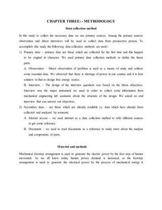
Mechanical footstep arrangement is used to generate the electric power by the foot step of human
movement. As we all know today human power demand is increased, so the footstep
arrangement is used to generate the electrical power by the process of mechanical energy is
2. converted into electrical energy in order to compensate the electric power demand.
Source: http://www.irjet.net
Fig.3.1 Schematic Representation of Foot Step
In this thesis work we are converting Mechanical energy into Electrical energy by utilize the
wasted energy in a useful way. By using Rack and Pinion arrangement we are converting motion
of the steps into rotational motion of the dynamo. In first foot step we are using rack and pinion
arrangement directly to rotate the shaft. But in second step we are using spur and pinion gear
mechanism to obtain better efficiency. Through Dynamo the rotational energy is converted into
electrical energy. This electrical energy output will be stored in the battery.
COMPONENTS USED FOR DESIGN
The foot step arrangement is constructed by steel plate or other material which is placed within
the surface areas and mainly placed in the crowed areas like at malls, walkways and other
different places. The material used for the construction of foot step arrangement is
Top Plate
Base plate
Rack and Pinion section
Gear arrangement
Springs
3. DC Generator
Shaft
LEDs
Bolts and nuts
L-bracket
Left /right support
Rod support
Top plate: plate where human footsteps and transfer the impact to the rack and pinion
arrangement.
Fig.3.2 Top plate
4. Base plate: it is a metal plate which carries the whole body of the design.
Fig.3.3 Base plate
Springs: A coil spring, also known as a helical spring, is a mechanical device which is
typically used to store energy and subsequently release it, to absorb shock, or to maintain a
force between contacting surfaces. They are made of an elastic material formed into the
shape of a helix which returns to its natural length when unloaded. It main purpose is to
return the upper plate to its original position after the load is removed.
5. Fig.3.4 spring
L-bracket: is used to support the main structure and used to connect left/right side support to
the base plate.
7. Left /right support: used to support the top plate the spring as well as the rod that connect
with the top plate.
Fig 3.6 Left /right support
8. Rod support: used to guide the rod which connect to top plat and make it move in right path of
back and forth.
Fig 3.7 Rod support
Rack and Pinion: A rack and pinion gears system is composed of two gears. The normal
round gear is the pinion gear and the straight or flat gear is the rack. A rack and pinion is
types of linear actuator that comprises a pair of gears which convert rotational motion into
9. linear motion. The circular pinion engages teeth on a linear "gear" bar which is called the
“rack“
Fig.3.8 Pinion and Rack
Gears: A gear is a rotating machine part having cut teeth which mesh with another toothed
part to transmit torque. Geared devices can change the speed, torque, and direction of a
power source. Gears almost always produce a change in torque, creating a mechanical
advantage, through their gear ratio, and thus may be considered a simple machine.
Fig.3.9 Gear arrangement
DC generator: DC generator is an electrical generator. This DC generator produces direct
current with the use of a commutator. The DC generator uses rotating coils of wire and
10. magnetic fields to convert mechanical rotation into a pulsing direct electric current. The
commutator is needed to produce direct current. When a loop of wire rotates in a magnetic
field, the magnetic flux through it, and thus the potential induced in it, reverses with each
half turn, generating an alternating current. It main purpose is by attaching with one of the
gear to generate electricity.
Shaft: Is a rotating machine element, usually circular in cross section, which is used to
transmit power from one part to another, or from a machine which produces power to a
machine which absorbs power. The pinion of the rack is mounted on this shaft as well as the
gear arrangement with transfers the mechanical power to the dc generator. it holds the gears,
upper plate and other parts together.
Fig.3.10 shaft
LEDs: it is a device that indicates that whether electricity is generated or not by giving light
when a foot step is applied. It is connected directly to the DC generator part.
Bolt: is a form of mechanical thread fastener with external male thread. It used to hold two or
materials together.
MECHANICAL DESIGN
The analysis contains only the structure, and the design will be performed efficiently when all
the dimensions, loads and requirements are met completely. The design for whole device comes
with top plate, base plate, 3 gears, and 1 rack with pinion, rod supports, left/right side support,
spring and generator.
11. DESCRIPTION OF ANALYSES
I. The amount of force that can apply on the top plate and springs
Now we assume that the maximum weight of human being is 100kg so we assume that
the amount of gravity is 9.81 m/𝑠2
from the force that applied on the top plate is
F=mass × acceleration=100kg×9.81 m/𝑠2
=981N
First we are going to calculate the reaction force that act on the left and right side spring.
Fig.3.11Reaction force at the top plate
Equilibrium equation
∑𝑓𝑥=0
∑ 𝑚𝐴=0
F×16cm + 𝑅𝐵×32cm=0
12. ∑ 𝑚𝐵=0
F×16cm - 𝑅𝐴×32cm =0
Reaction at point B
𝑅𝐵=
(981𝑁×16cm )
32cm
= 490.5N
Reaction at point A
𝑅𝐴=
(100×16cm)
32cm
= 490.5N
Bending moment
𝑀1 (at 16cm)= 490.5N×16cm
=7848Ncm=78.48Nm
𝑅𝐴 And 𝑅𝐵 these reaction forces are the force that act on the spring by the weight of man who
walks on the top plate
And 𝑀1 is the bending monument of the top plate when 100kg amount of weight is applied on
the top plate of the machine at a distance of 16cm away from reaction forces.
II. Now we can calculate or design the spring that we use in the machine
Using hooks law for the spring we can find the spring constant
Force (𝐹) =490.5N
Length of the spring (L) =10cm
Distance for compression (X) =5cm
To find the spring constant use this equation
𝑅𝐵 Or 𝑅𝐴=𝐾 ∗ X where k=spring constant, X= the distance moved by the sprig when force
(𝐹) exert on it
𝑅𝐵=𝐾 ∗ X
𝐾=
𝑅𝐵
𝑋
=
490.5𝑁
10𝑐𝑚
=490.5kN/m
We use the spring that has a spring constant (k) = 490.5kN/m
13. III. The weight of top plate
The given parameters’ are
Height (H) = 15cm
Length (L) = 40cm
Width (W) =0.5cm
Density of steel =7850
𝑘𝑔
𝑚3
Here we can find the volume (V) and the weight (𝑊
𝐺 ) of the top plate.
V=L×W×H= 0.15×0.005×0.4=3× 10⁻⁵
𝑚3
Weight =density × volume
𝑊𝐺 =3× 10⁻⁵
𝑚3
× 7850
𝑘𝑔
𝑚3
𝑊𝐺 =1.8𝑘𝑔
IV. Tangential force on the rack
If we use the rack for the vertical application than the tangential force of the rack is given
by
𝐹𝑟=𝑚𝑔 + 𝑚𝑎+𝐹𝑒
Where
𝐹𝑟 =Tangential force of rack
𝐹𝑒=pressing force for the application
𝑚= moved mass; includes mass of top plate and any other mass that has effect on the rack
𝑔 =Force of gravity
𝑎=maximum acceleration that the machine experience but in our case the only acceleration is “g”
since there is no velocity change.
𝐹𝑟=𝑚(𝑔 + 𝑎) + 𝐹𝑒=1.8kg (9.81𝑚
𝑠2
⁄ +0) +981N
𝐹𝑟=17.658N + 981N=998.658N
14. V. Torque on the pinion
The torque on the pinion is simply multiply the tangential force of the rack by radius of
the pinion
We take the diameter of the pinion is 2.5cm our reason to take this dimension it is when
the crack move 5cm our pinion will rotate two full rotation so we can produce maximum
amount of torque.
T=𝐹𝑟×𝑟𝑃 where: - 𝐹𝑟 =tangential force of rack
𝑟𝑃 =radius of pinion
𝑇=torque on the pinion
T=998.658N × 1.25cm =12.48Nm
VI. The maximum permissible torque for the shaft with known dimension
The maximum Permissible shear stress on the shaft is (𝜏) 90Mpa that the shaft material can
handle
𝑑2= 1.25cm → 𝑐2= 0.75cm where: - 𝑑2=outer diameter of the shaft
𝑐2=outer radius of the shaft
𝑑1= 0.75cm → 𝑐1= 0.375cm 𝑑1=inner diameter of the shaft,
𝑐2=inner radius of the shaft
First find the value of inertia “J”
J=
𝜋
2
(𝐶2
4
− 𝐶1
4
) =
𝜋
2
((0.00754
− 0.003754
))
J =4.657×10⁻⁹
𝑚4
Now find the maximum torque using the equation
𝜏 =
𝑇𝑐2
𝐽
= where: - 𝑇𝑚 = the maximum torque that the material can handle
𝑇𝑚 =
𝜏𝐽
𝑐
=
90𝑀𝑝𝑎 ×4.657 ×10−9
𝑚4
0.0075𝑚
𝜏=given maximum permissible torque
𝑇𝑚= 55.884 Nm
So as we see the maximum torque that the material can handle is greater than that of the machine
will experience (T<𝑇𝑚) when it implement so our shaft is safe to use.
15. VII. EMF generated by the DC generator
Since we use wave winded type of generator we use the formula given by
Reasons why we choose wave winded type of generator
Basic comparison Lap winded generator wave winded generator
Definition The coil is lap back to the
succeeding coil.
The coil of the winding form the
wave shape.
EMF Less More
Winding Cost High (because more
conductor is required)
Low
Efficiency Less High
Parallel Path The numbers of parallel
path are equal to the total
of number poles.
The number of parallel paths is
equal to two.
Uses In low voltage, high
current machines.
In high voltage, low current
machines.
𝐸𝑔 =
ψZPn
60𝐴
where: - Z=number of conductor=P×A
P=number of pole
𝑛=speed of rotor
𝐸𝑔=EMF generated
𝐴=number of parallel path in this case it is half of
the number of pole
We use wave winded generator that have 4 pole and number of conductor 4
First we calculate the speed of rotor using the formula of
The velocity or the speed is 0.5m/s because the downward and upward movement of the
rack is occur with is a second and it move only 5cm so speed
𝑛=
𝑠
𝑡
where: - s =the distance moved by the rack
t= time taken to move that distance
𝐸𝑔 =
0.2×4×8×0.5
60×2
=0.3v
16. VIII. The weight of base plate
The given parameters’ are
Height (H) = 20cm
Length (L) = 35cm
Width (W) =0.5cm
Density of steel =7850
𝑘𝑔
𝑚3
Here also we can find the volume (V) and the weight (𝑊𝐺 ) of the top plate.
V=L×W×H= 0.20×0.005×0.35=3.5× 10⁻⁴
𝑚3
Weight =density × volume
𝑊𝐺 =3.5× 10⁻⁴
𝑚3
× 7850
𝑘𝑔
𝑚3
𝑊𝐺 =2.75𝑘𝑔
IX. Volume of a box for the device.
Here we are going to calculate the box for a device or a total place where covered by the
device when it implemented in real world.
Length of the device (L) = 40cm
Height of the device (H) = 35cm
Width of the device (W) = 25cm
Now we can find the volume (V) of the device
V=L×W×H=400cm×35cm×25cm=0.4375𝑚3
When we implemented the machine will cover 0.4375𝑚3
this amount of volume.
17. WORKING PRINCIPLE
The basic working principle of this project is based on the rack and pinion arrangement to
implements this we adjust the steel plates above and below the gear system and moveable
springs. The spring, rack and pinion arrangement is fixed below the foot step which is mounted
on base. Spring system is used for return mechanism of upper plate after release of load. The
upper plate is mounted on two springs; the weight impact is converted into electrical power. The
shaft along with pinion is supported by end bearings. The shaft along with pinion is supported by
end bearings a gear is provided there also. When the pressure is applied, the rack pressures the
pinion to move and the linear motion is converted into rotational motion a gear is coupled to the
shaft. The weight impact is converted into electrical power with proper control unit. To the
pinion shaft DC generator is provided and LEDs are coupled to it. The gear wheel which is
provided in shaft is coupled to the DC generator. . From the DC generator the wires are taken.
These wires are connected to LEDs, to display the output power. Thus Mechanical energy is
converted in to Electrical energy.
The working of mechanical Foot Step power generation is demonstrated:
I. When force is applied on the plate by standing on plate the spring gets compressed.
II. The rack moves vertically down.
III. The pinion meshed with the rack gear results in circular motion of the pinion gear.
IV. For one full compression the pinion Moves one semicircle, when the force applied on the
plate released the pinion reverses and moves another semicircle.
V. When the force is released from the plate pinion reverses and moves another circle and cause
rotation of gear pairs.
VI. The generator attached to the last gear hence results in the dc power generation. The power
generated by the foot step generator can be stored in an energy storing device.
18. The complete diagram of the footstep power generation is given below
Fig.3.12 Flow diagram of power generation
Human foot on the top
plate
Rack and pinion
arrangement
Gear pairs
Dynamo or generator
LEDs