Download to read offline

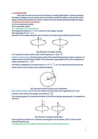
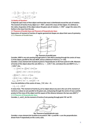
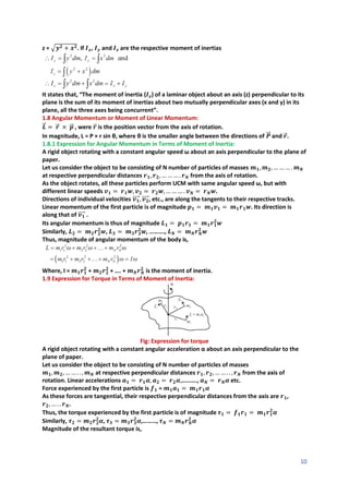
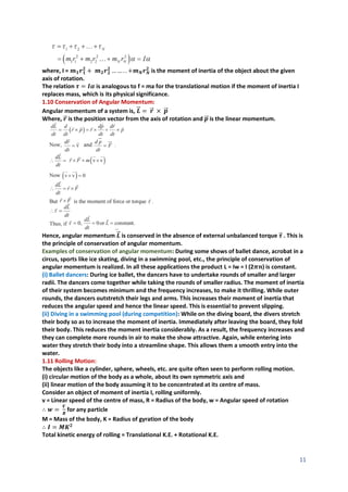
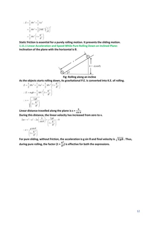

1. The document discusses rotational dynamics and circular motion. It defines concepts like angular velocity, moment of inertia, centripetal force, and radius of gyration. 2. Examples of circular motion discussed include vehicles moving in circular tracks, wells of death, and vehicles on banked roads. The forces and equations of motion are analyzed. 3. Vertical circular motion under gravity is also examined, like a point mass attached to a string or rod moving in a vertical circle. Dynamics of a vehicle on a convex overbridge are also covered. 4. Moment of inertia is introduced as an analogous concept to mass for rotational motion. Formulas are given for moment of inertia of objects like rings, discs, and


