
Recommended
More Related Content
Similar to Equation for reflection.pdf
Similar to Equation for reflection.pdf (20)
Recently uploaded
Recently uploaded (20)
Equation for reflection.pdf
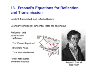
- 1. 13. Fresnel's Equations for Reflection and Transmission Incident, transmitted, and reflected beams Boundary conditions: tangential fields are continuous Reflection and transmission coefficients The "Fresnel Equations" Brewster's Angle Total internal reflection Power reflectance and transmittance Augustin Fresnel 1788-1827
- 2. Posing the problem What happens when light, propagating in a uniform medium, encounters a smooth interface which is the boundary of another medium (with a different refractive index)? k-vector of the incident light boundary nincident ntransmitted First we need to define some terminology.
- 3. Definitions: Plane of Incidence and plane of the interface Plane of incidence (in this illustration, the yz plane) is the plane that contains the incident and reflected k-vectors. x y z Plane of the interface (y=0, the xz plane) is the plane that defines the interface between the two materials
- 4. Definitions: “S” and “P” polarizations 2. “P” polarization is the parallel polarization, and it lies parallel to the plane of incidence. 1. “S” polarization is the perpendicular polarization, and it sticks up out of the plane of incidence The plane of the interface (y=0) is perpendicular to this page. Here, the plane of incidence (z=0) is the plane of the diagram. x y z I R T A key question: which way is the E-field pointing? There are two distinct possibilities.
- 5. reflected light reflecting medium Definitions: “S” and “P” polarizations The amount of reflected (and transmitted) light is different for the two different incident polarizations. Note that this is a different use of the word “polarization” from the way we’ve used it earlier in this class.
- 6. ni nt i k r k t k i r t Ei Bi Er Br Et Bt Interface x y z Beam geometry for light with its electric field sticking up out of the plane of incidence (i.e., out of the page) We treat the case of s-polarization first: the xz plane (y = 0) Augustin Fresnel was the first to do this calculation (1820’s). Fresnel Equations—Perpendicular E field
- 7. ni nt i k r k t k i r t Ei Bi Er Br Et Bt Interface Boundary Condition for the Electric Field at an Interface: s polarization x y z In other words, The Tangential Electric Field is Continuous So: Ei(y = 0) + Er(y = 0) = Et(y = 0) The component of the E-field that lies in the xz plane is continuous as you move across the plane of the interface. Here, all E-fields are in the z-direction, which is in the plane of the interface. (We’re not explicitly writing the x, z, and t dependence, but it is still there.)
- 8. Boundary Condition for the Magnetic Field at an Interface: s polarization ni nt i k r k t k i r t Ei Bi Er Br Et Bt Interface x y z i i *It's really the tangential B/, but we're using i t 0 –Bi(y = 0) cosi + Br(y = 0) cosr = –Bt(y = 0) cost The Tangential Magnetic Field* is Continuous In other words, The total B-field in the plane of the interface is continuous. Here, all B-fields are in the xy-plane, so we take the x-components:
- 9. Reflection and Transmission for Perpendicularly Polarized Light Ignoring the rapidly varying parts of the light wave and keeping only the complex amplitudes: 0 0 0 0 0 0 cos( ) cos( ) cos( ) i r t i i r r t t E E E B B B 0 0 0 0 0 0 0 0 : ( )cos( ) ( )cos( ) Substituting for using t i r t i r i i t r i t E E E E n E E n E E 0 0 0 ( )cos( ) cos( ) i r i i t t t n E E n E 0 0 /( / ) / . But and i r B E c n nE c Substituting into the second equation:
- 10. Reflection & Transmission Coefficients for Perpendicularly Polarized Light 0 0 0 0 0 0 ( )cos( ) ( )cos( ) : cos( ) cos( ) cos( ) cos( ) i r i i t r i t r i i t t i i i t t n E E n E E E n n E n n Rearranging yields 0 0 / 2 cos( ) / cos( ) cos( ) t i i i i i t t t E E n n n 0 0 / , is transmission coefficient Analogously, the , t i E E 0 0 / cos( ) cos( ) / cos( ) cos( ) r i i i t t i i t t r E E n n n n 0 0 / Solving for yields t reflection coefficient he : r i E E These equations are called the Fresnel Equations for perpendicularly polarized (s-polarized) light.
- 11. ni nt i k r k t k i r t Ei Bi Er Br Et Bt Interface × Fresnel Equations—Parallel electric field x y z Beam geometry for light with its electric field parallel to the plane of incidence (i.e., in the page) Note that the reflected magnetic field must point into the screen to achieve for the reflected wave. The x with a circle around it means “into the screen.” E B k Note that Hecht uses a different notation for the reflected field, which is confusing! Ours is better! This leads to a difference in the signs of some equations... Now, the case of P polarization:
- 12. Reflection & Transmission Coefficients for Parallel Polarized Light These equations are called the Fresnel Equations for parallel polarized (p-polarized) light. || 0 0 / cos( ) cos( ) / cos( ) cos( ) r i i t t i i t t i r E E n n n n || 0 0 / 2 cos( )/ cos( ) cos( ) t i i i i t t i t E E n n n Solving for E0r / E0i yields the reflection coefficient, r||: Analogously, the transmission coefficient, t|| = E0t / E0i, is For parallel polarized light, B0i B0r = B0t and E0icos(i) + E0rcos(r) = E0tcos(t)
- 13. To summarize… || cos( ) cos( ) cos( ) cos( ) i t t i i t t i n n r n n || 2 cos( ) cos( ) cos( ) i i i t t i n t n n 2 cos( ) cos( ) cos( ) i i i i t t n t n n cos( ) cos( ) cos( ) cos( ) i i t t i i t t n n r n n s-polarized light: p-polarized light: And, for both polarizations: sin( ) sin( ) i i t t n n plane of incidence incident wave transmitted wave interface plane of incidence incident wave transmitted wave interface E-field vectors are red. k vectors are black.
- 14. Reflection Coefficients for an Air-to-Glass Interface Incidence angle, i Reflection coefficient, r 1.0 .5 0 -.5 -1.0 r|| r┴ 0° 30° 60° 90° The two polarizations are indistinguishable at = 0° Total reflection at = 90° for both polarizations. nair 1 < nglass 1.5 Brewster’s angle r||=0! Zero reflection for parallel polarization at: “Brewster's angle” The value of this angle depends on the value of the ratio ni/nt: Brewster = tan-1(nt/ni) Sir David Brewster 1781 - 1868 For air to glass (nglass = 1.5), this is 56.3°.
- 15. Incidence angle, i Reflection coefficient, r 1.0 .5 0 -.5 -1.0 r|| r┴ 0° 30° 60° 90° Brewster’s angle Total internal reflection Critical angle Critical angle Total internal reflection above the "critical angle" crit sin-1(nt /ni) 41.8° for glass-to-air nglass > nair (The sine in Snell's Law can't be greater than one!) Reflection Coefficients for a Glass-to-Air Interface
- 17. Reflectance (R) R Reflected Power / Incident Power r r i i I A I A Because the angle of incidence = the angle of reflection, the beam’s area doesn’t change on reflection. Also, n is the same for both incident and reflected beams. A = Area 2 0 0 0 2 c I n E i wi ni nt r wi 2 R r So: since 2 0 2 2 0 r i E r E
- 18. Transmittance (T) t t i i I A I A A = Area 2 0 0 0 2 c I n E cos( ) cos( ) t t t i i i A w A w t i wi wt ni nt If the beam has width wi: 2 0 0 2 0 0 2 2 2 0 0 0 0 2 2 t t t t t t t t t t i i i i i i i i i i c n E n E w I A w n w T t c I A w n w n E w n E The beam expands (or contracts) in one dimension on refraction. since 2 0 2 2 0 t i E t E 2 cos cos t t i i n T t n T Transmitted Power / Incident Power
- 19. Reflectance and Transmittance for an Air-to-Glass Interface Note that it is NOT true that: r + t = 1. But, it is ALWAYS true that: R + T = 1 Perpendicular polarization Incidence angle, i 1.0 .5 0 0° 30° 60° 90° R T Parallel polarization Incidence angle, i 1.0 .5 0 0° 30° 60° 90° R T Brewster’s angle
- 20. Perpendicular polarization Incidence angle, i 1.0 .5 0 0° 30° 60° 90° R T Reflectance and Transmittance for a Glass-to-Air Interface Parallel polarization Incidence angle, i 1.0 .5 0 0° 30° 60° 90° R T Note that the critical angle is the same for both polarizations. And still, R + T = 1
- 21. Reflection at normal incidence, i = 0 2 t i t i n n R n n 2 4 t i t i n n T n n When i = 0, the Fresnel equations reduce to: For an air-glass interface (ni = 1 and nt = 1.5), R = 4% and T = 96% The values are the same, whichever direction the light travels, from air to glass or from glass to air. This 4% value has big implications for photography. “lens flare”
- 22. Windows look like mirrors at night (when you’re in a brightly lit room). One-way mirrors (used by police to interrogate bad guys) are just partial reflectors (actually, with a very thin aluminum coating). Disneyland puts ghouls next to you in the haunted house using partial reflectors (also aluminum-coated one- way mirrors). Smooth surfaces can produce pretty good mirror-like reflections, even though they are not made of metal. Where you’ve seen Fresnel’s Equations in action
- 23. Optical fibers only work because of total internal reflection. Fresnel’s Equations in optics R = 100% R = 90% Laser medium 0% reflection! 0% reflection! Many lasers use Brewster’s angle components to avoid reflective losses: