Final year mechanical projects in bangalore
•Download as DOCX, PDF•
1 like•180 views

final year ece in bangalore,final year eee projects in bangalore,chennai,final year mechanical projects in bangalore,final year embedded system projects in bangalore,chennai

Recommended
More Related Content
What's hot
What's hot (20)
Similar to Final year mechanical projects in bangalore
Similar to Final year mechanical projects in bangalore (20)
More from Ashok Kumar.k
More from Ashok Kumar.k (11)
Recently uploaded
Recently uploaded (20)
Final year mechanical projects in bangalore
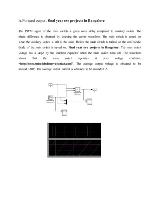
- 1. A.Forward output : final year cse projects in Bangalore The PWM signal of the main switch is given some delay compared to auxiliary switch. The phase difference is obtained by delaying the carrier waveform. The main switch is turned on while the auxiliary switch is still in the state. Before the main switch is turned on the anti-parallel diode of the main switch is turned on. Final year eee projects in Bangalore. The main switch voltage has a slope by the snubbed capacitor when the main switch turns off. The waveform shows that the main switch operates at zero voltage condition. “http://www.embeddedinnovationlab.com”. The average output voltage is obtained to be around 380V. The average output current is obtained to be around38 A.
- 2. Reverse output We then compared the torque outputs of without soft switching model and IGBT soft switching model as shown in Fig. 7 and Fig. 8 respectively. Maximum torque in both models is 14 N-m. As clear from the output, torque start decreasing in interval (0-0.01 sec) and after that it becomes constant up to 0.22 sec and further decreases and becomes negative. Final year embedded system projects in Chennai. After that it again starts increasing and becomes constant in interval from 0.23 sec to 0.5 sec. From 0.5 sec it again starts increasing to maximum value and after that it again decreases and become constant for the model without soft switching. Torque in soft switching model decreasing in interval (0-0.01 sec) and after that it become constant up to 0.3 sec and further decreases and become negative. http://www.embeddedinnovationlab.com After that it again starts increasing and becomes constant in interval from 0.3 sec to 0.5 sec. From 0.5 sec it again starts increasing to maximum value and after that it again decreases and become constant. http://www.embeddedinnovationlab.com.From the outputs we observed that torque improves with soft switching technique. Finally, we compared the voltage outputs of without soft switching model and IGBT soft switching model whose outputs are shown in Fig. 9 and Fig. 10.Voltage in without soft switching model decreases first and after that it becomes constant. In soft switching model, voltage remains constant over the whole period. So we can infer that there is no effect on the bus voltage when motor starts with soft switching. The named as ‘isolated switched-capacitor tapped-inductor (SCTI) boost converter’. The proposed converter consists of two parts. The primary side has a TI boost converter with a
- 3. singlemain switch controlled by a PWM compensator and a gatedriver. The secondary side has an isolated charge pump. From the inductor tapping, the main switch voltage stress is Reduced, final year mechanical projects in Chennai. And the voltage spike on the switch is significantly attenuated. Given that low voltage stress exists on the active switch, the circuits can use low voltage MOSFETs, which generally have low Rds(on). MOSFETs decrease the conduction loss dramatically [10], thus making this variable one of the dominant factors of efficiency. http://www.embeddedinnovationlab.com. The output of the switched cell is connected with the boost output in series. The stacked-output structure of the proposed converter is suitable for high-voltage and low-current applications. Compared with other multiple-module connected topologies, MOSFET and diode are relieved from severe voltage stress. The DCM is also employed to eliminate the reverse-recovery loss of the diode. http://www.embeddedinnovationlab.com