
Recommended
More Related Content
Similar to Measuring the NA of an Optical Fiber
Similar to Measuring the NA of an Optical Fiber (20)
Recently uploaded
Recently uploaded (20)
Measuring the NA of an Optical Fiber
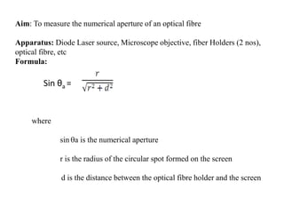
- 1. Aim: To measure the numerical aperture of an optical fibre Apparatus: Diode Laser source, Microscope objective, fiber Holders (2 nos), optical fibre, etc Formula: Sin θa = where sin a is the numerical aperture r is the radius of the circular spot formed on the screen d is the distance between the optical fibre holder and the screen
- 2. Diagram:
- 3. Figure 2
- 4. Fig.3 Schematic representation of the Experimental Set up
- 5. Actual Set up of the experiment in the Lab.
- 6. Theory: Optical fibers are fine transparent glass or plastic fibers which can propagate light. They work under the principle of total internal reflection from diametrically opposite walls. In this way light can be taken anywhere because fibers have enough flexibility. This property makes them suitable for data communication, design of fine endoscopes, micro sized microscopes etc. An optic fiber consists of a core that is surrounded by a cladding which are normally made of silica glass or plastic. The core transmits an optical signal while the cladding guides the light within the core. Since light is guided through the fiber it is sometimes called an optical wave guide. The basic construction of an optic fiber is shown in figure (1). In order to understand the propagation of light through an optical fibre, consider the figure (2). Consider a light ray (i) entering the core at a point A , travelling through the core until it reaches the core cladding boundary at point B. As long as the light ray intersects the core-cladding boundary at a small angles, the ray will be reflected back in to the core to travel on to point C where the process of reflection is repeated .ie., total internal reflection takes place. Total internal reflection occurs only when the angle of incidence at core/cladding interface is greater than the critical angle. If a ray enters an optic fiber at a steep angle(ii), when this ray intersects the core-cladding boundary, the angle of intersection is too large. So, reflection back in to the core does not take place and the light ray is lost in the cladding. This means that for light to be guided through an optic fibre, a light ray must enter the core with an angle less than a particular angle called the acceptance angle of the fibre. A ray which enters the fiber with an angle greater than the acceptance angle will be lost in the cladding.
- 7. The significance of NA is that light entering in the cone of semi vertical angle im only propagate through the fibre. The higher the value of im or NA more is the light collected for propagation in the fibre. Numerical aperture is thus considered as a light gathering capacity of an optical fibre. Numerical Aperture is defined as the Sine of half of the angle of fibre’s light acceptance cone. i.e. NA= Sin θa where θa, is called acceptance cone angle.
- 8. Procedure: 1. Mount Laser source, objective and detector on the respective holders. 2. Mount both the ends of the optical fibre on the fibre holders. 3. Align the different objects as per the setup shown below. 4. Couple the light from the laser source onto one of the fibre ends using a microscopic objective (provided with the kit). 5. Light from the laser is coupled into the given optical fibre by using microscope objective. 6. Switch ON the Laser source and focus the light from the optical fibre on the screen provided. 7. A red spot appears on the screen. 8. Note down the distance between the optical fibre holder and the screen (d). 9. Note down the diameter of the luminous red spot produced on the screen (D) and from this calculate the radius of the spot . 10. Substitute the values of r and d in the formula for numerical aperture to calculate the same. 11. Repeat the same experiment for different values of d.
- 9. S.No. Distance between the screen and optical fibre holder d (cm) Diameter of the spot on the screen D (cm) r = D/2 Numerical Aperture 1. 2. 3. Observation Table
- 10. Result: Numerical Aperture of given optical fibre = ....... Precautions: 1. Mounting and coupling should be carefully done. 2. Care should be taken so that laser light should not directly fall into the eye. 3. As far as possible, experiment should be conducted in dark room environment.