1. Fiber optics
1 Introduction
From time to time scientists have tried to design and improve communication system
by which messages are sent over long distances. The communications system consists of the
three parts viz (i) transmitter (ii) transmission channel (iii) receiver using a transmission
line, the signal gets progressively attenuated and distorted. So the improvement in the
communication process would mean motivation to improve the transmission fidelity and at
the same time to improve the data rate of transmission.
With the development of lasers, reliable and powerful coherent radiation became
available. So it was natural to use this light for communication purposes. There are two
reasons for this (i.e.) (i) higher frequency and (ii) more information carrying capacity
compared to conventional radio and micro-wave carriers. We also know that light waves
cannot travel far in open atmosphere as the energy gets very rapidly dissipated. Hence some
kind of guiding channel is needed just like for guiding electric current a conducting path, like
a metal wire, is needed. Optical fiber provides the necessary wave guide for light.
Fiber optics is a technology related to transportation of optical energy (light energy)
in guiding media specifically glass fibers.
3.2 Optical fiber
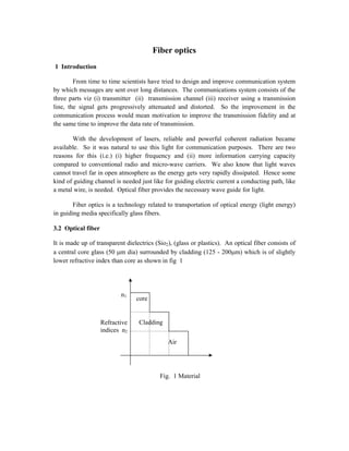
It is made up of transparent dielectrics (Sio2), (glass or plastics). An optical fiber consists of
a central core glass (50 m dia) surrounded by cladding (125 - 200m) which is of slightly
lower refractive index than core as shown in fig 1
Fig. 1 Material
Refractive
indices n2
core
Cladding
Air
n1
2. Fig. 2 Structure of an optical fiber
The cladding is enclosed by the strength members like (Kevlar) and polyurethane jacket,
which acts as protective skin for core and cladding, as shown in fig 2, the protective layer is
used so as to make the optical cable to withstand for hard pulling, bending, sketching, rolling
etc. The layer also traps the escaping light from the core.
3.3 Principle and propagation of light in optical fibers
For optical fibers, the process of propagation of light is simple, because once the light
enters the fiber, the rays do not encounter any new surfaces but repeatedly they hit the same
surface. The reason of confining the light beam inside the fibers is the total internal
reflection.
Even for a bent fiber, the light guidance take place by multiple total internal
reflections all over the length of the fiber as shown in fig 3
Principle
The principle of optical fiber communication is Total Internal Reflection
Total Internal Reflection
The phenomenon of Total Internal Reflection takes place when it satisfied the
following two conditions.
1. Light should travel from denser medium to rarer medium
(i.e.) n1 > n2
Where n1 = refractive index of core
n2 = refractive index of cladding
2. The angle of incidence on core should be greater than the critical angle
(i.e.) >c
Where = angle of incidence & c = critical angle
3. Fig 3
Propagation phenomenon
Let the light ray passes from denser medium to rarer medium.
Case (i) when < c, the ray is refracted into the rarer medium as shown in fig 4
Fig 4
Case (ii) when = c, the ray passes along the interface as shown in fig 5. So that
the angle of refraction is 900
. This angle (c) is called as critical angle
Fig 5
core
Cladding (n2)
rarer medium Refracted
Ray
Core n1
Denser medium
Cladding (n2)
rarer medium
n1
n1 > n2
< c
Cladding (n2)
Core n1
Cladding (n2)
n1
c
900
n1 > n2
cladding
= c
4. Case (iii) when > c, the ray is totally reflected back into the denser medium itself
as shown in fig 6
> c
Fig 6
From Snell’s law
n1 sin 1 = n2 sin 2 ……………(1)
[When,1 = c & 2 = 900
], then eqn. (1) becomes,
n1 sin c = n2 sin 90 …………….(2)
= [sin 90 = 1] ………..(3)
From eqn.(3), we get
∅ =
4 Acceptance angle and Numerical aperture
`
Fig 7 Path of typical ray launched into a fiber
Cladding (n2)
Totally internally
Reflected Ray
Core n1
Cladding (n2
c
n1 > n2
Normal to core wall
Cladding n2
Totally internally
Reflected Ray
Core n1
Cladding (n2)
c
n1 > n2
> c
0
B
r
Core
n1
i
A
C
Launch zone n0
Fiber axis
normal to
core face
Typical ray path
into fiber
Fiber end face
5. Acceptance angle can be defined as the maximum angle of launch that a light can
suffer total internal reflection. The cone is referred as acceptance cone.
Fig 7 shows a longitudinal cross section of the launch end of a fiber with a ray
entering it. The light is launched from a medium of refractive index n0 (n0 = 1 for air) into
core of refractive index n1. The ray enters with an angle of incidence i to the fiber end face.
This particular ray enters the core at its axis point A and proceeds after refraction at an angle
r from the axis. It then undergoes total internal reflection at B on core wall at an internal
incidence angle . Let us now find up to what value of i at A, total internal reflection at B
is possible. From triangle ABC,
r + + 900
= 1800
r = 9 - …………….. (1)
From Snell’s law,
n0 sin i = n1 sin r ……………..(2)
∝ = sin (90 − ) [ r =90 - ]
∝ = cos …………….. (3) [sin(90 - )=cos]
Let i (max) be the maximum possible angle of incidence at the fiber end face at A
for which is equal to c to suffer total internal reflection. If for a ray i exceeds i (max),
then will be less than c and hence at B the ray will be refracted.
Hence eqn (3) can be written as
(max) = cosθc..........(4)
We know that
=
cos c = 1 – sin2
c
= 1 − = − / …………(5)
Eq (4) becomes
sin i (max) = n1/n0 n1
2
– n2
2
/ n1
2
sin i (max) = n1
2
– n2
2
n0
i (max) = sin -1
[n1
2
– n2
2
] …………………(6)
n0
This maximum angle is called the acceptance angle
Rotation of the acceptance angle about the fiber axis as shown in fig 8 describes the
acceptance core of the fiber. Light launched at the fiber end within this acceptance core will
6. be accepted and propagated to the other end of the fiber by total internal reflection. Larger
acceptance angle make launching easier.
Fig. 8
Numerical aperture
‘Numerical aperture’ is defined as the sine of the maximum acceptance angle of the
fiber.
NA = sin i (max) = n1
2
– n2
2
……………….. (7)
n0
Fractional Index change ()
It is the ratio of refractive index difference in core and cladding to the refractive index
of core.
(ie) = n1 – n2 ………………..(8)
n1
n1 = n1 – n2 ………………..(9)
We known NA = n1
2
– n2
2
(Or) = (n1+n2) (n1-n2) ………………… (10)
Substituting equation (9) in eqn (10) we have
(or) NA = (n1+n2) n1
If n1n2, then NA = 2n1
2
NA = n12 …………….(11)
7. 5 Types of optical fibers based on materials, modes and refractive indices
6 Glass and Plastic fibers
Based on materials in which the fibers are made it is classified into two types as
follows:
Glass fibers
If the fibers are made up of mixture of metal oxides and silica glasses
Examples:-
The glass fibers can be made by any one of the following combinations of core and
cladding
(i) core : Sio2 ; cladding P2O3 – Sio2
(ii) core : Geo2 – Sio2 ; cladding : Sio2
Plastic fibers
If the fibers are made up plastics which can be handled without any care due to its
toughness and durability it is called plastic fiber.
Examples:-
The plastic fibers are made by any one of the following combinations of core and
cladding.
(i) core : Polymethyl methacrylate ; cladding: co-polymer
(ii) core : Polystyrene; cladding: Methyl methacrylate
7 Single and multimode fibers
Mode is the one which describes the nature of propagation of electromagnetic waves
in a wave guide.
Optical fibers are based on
Material No. of modes Refractive indeed profile
Glass
fiber
Plastic
fiber
Single
mode fiber
Multi mode
fiber
Step
index
fibre
Graded
indexfibe
r
8. Based on the modes of propagation the fibers are classified into two types viz.
(i) Single mode fibers
(ii) Multi mode fibers
(i) Single mode fibers
In general the single mode fibers are step index fibers. These type of fibers are made
from doped silica. It has a very small core diameter so that it can allow only one mode of
propagation and hence called single mode fibers. The cladding diameter must be very large
compared to the core diameter. Thus in the case of a single mode fiber, the optical loss is
very much reduced. The structure of a single mode fiber is shown in fig. 9.
Fig 9
Structure
Core diameter : 5 – 10 m
Cladding diameter : Around 125 m
Protective layer : 250 to 1000 m
Numerical aperture : 0.08 to 0.10
Band width : More than 50 MHz km
Application
Because of its high band width, they are used in long distance communication
systems.
(ii) Multi-mode fibers:
The multimode fibers are useful in manufacturing both for the step index and graded
index fibers. The multimode fibers are made by multi-component glass compounds such as
glass-clad-glass, silica-clad-silica, etc. Here the core diameter is also larger than the diameter
of the single mode fibers, so that it can allow many modes to propagate through it and hence
called as multimode fibers. The structure of the multimode fiber is shown in fig 10.
n1
n2
9. Fig. 3.10
Structure :
Core diameter : 50 – 350 m
Cladding diameter : 125 – 500 m
Protective layer : 250 to 1100 m
Numerical aperture : 0.12 to 0.5
Band width : Less than 50 MHz km
Application
Because of its less bandwidth it is very useful in short distance communication
systems.
8. Step index and graded index fibers:-
Based on the variation in the refractive index of the core and the cladding, the fibers
are classified into two types, viz.
(i) step index fiber
(ii) graded index fiber
(i) Step index fiber
Here the refractive indices of air, cladding and core vary step by step and hence it is
called as step index fiber.
In step index fiber we have both single mode and multimode fibers as shown in fig
11 & fig 12 respectively.
n1
n2
10. Fig. 12 Multi mode step Index fiber
Cladding
Cladding
Air Ray Propagation
Air
Core (n1)
Cladding (n2)
Air (n0)
r – Radius of Fiber
n – Refractive index of fiber
Cladding
Cladding
Air Ray Propagation
Air
r – Radius of Fiber
n – Refractive index of fiber
n
n1
n2
n0
Fig 3.11 Single mode step index fiber
11. Transmission of signal in step index fiber:-
Fig. 13 Signal transmissions in step index fiber
Generally the signal is sent though the fiber in digital form (i.e.) in the form of pulses
representing 0s and 1s. Let us now consider the propagation of one such pulse through
multimode fiber. The same pulsed signal travels in different paths (represented by
multimodes). Hence at the receiving end only ray (1) which travels along the fiber axis
reaches first while the rays taking zigzag path (2) reach after some time delay. Hence the
pulsed signal received at the other end is broadened. This is called intermodal dispersion.
This imposes limitation on the separation between pulses thereby reducing the transmission
rate and capacity. This difficulty is overcome by manufacturing graded index fiber.
(ii) Graded index fiber (GRIN)
Here the refractive index of the core varies radically from the axis of the fiber. The
refractive index of the core is maximum along the fiber axis and its gradually decreases thus
it is called as graded index fiber. Here the refractive index becomes minimum at the core –
cladding interface. In general the graded index fibers will be of multimode system. The
multimode graded index fiber has very less intermodal dispersion compared to multimode
step index fiber. A typical multimode graded index fiber is shown in fig 14.
Transmission of signal in graded index fiber
2
1
core
Air Ray Propagation
Air
n1
n2
n0
Cladding
Cladding
Cladding
n
Fig. 3.14 Graded index fiber
12. Fig. 15 Propagation of different model rays inside graded index fiber
Let us now consider a signal pulse travelling through graded index fiber in two
different paths 1 and 2. The pulse 1 travelling along the axis of the fiber, though travels
along shorter route, it travels through a medium of higher refractive index. The other pulse 2,
travelling away from the axis undergoes refraction and bends as shown in the fig 15.
Though it travels longer distance, it travels along the path possessing relatively lesser
refractive index and hence both the pulses reach the other end simultaneously. Thus the
problem of intermodal dispersion can be overcome by using graded index fiber.
11 Losses in optical fibers
When light propagates through an optical fiber, a small percentage of light is lost
through different mechanisms. The loss of optical power is measured in terms of decibels per
kilometer for attenuation losses.
Attenuation
It is defined as the ratio of the optical power output (Pout) from a fiber of length (L in
kilometers) to the power input (Pin).
- 10 Pout
Attenuation () = log dB/ km
L Pin
Since attenuation plays a major role in determining the transmission distance, the
following attenuation mechanisms are to be considered in designing an optical fiber.
1. Absorption
2. Scattering
3. Radiative losses
1. Absorption
2
1
core
13. Usually absorption of light occurs due to imperfections of the atomic structure such as
missing molecules, (OH–
) hydroxyl ions, high density cluster of atoms etc., which absorbs
light.
Absorption also depends on the wavelength of the light used. The three bands of
wavelength at which the absorption increases drastically is 950nm, 1250nm and 1380nm.
For example, at the wavelength say 850 nm the absorption is 1.5 dB/km and for 1500 nm, it
is 0.5 dB/km.
2. Scattering
Scattering is also a wavelength dependent loss, which occurs inside the fibers. Since
the glass is used in fabrication of fibers, the disordered structure of glass will make some
variation in the refractive index inside the fiber. As a result, if light is passed through the
atoms in the fiber, a portion of the light is scattered (elastic scattering). This type of
scattering is called Rayleigh scattering
Rayleigh Scattering Loss 1 / 4
Radiative losses
Radiative loss occurs in fibers, due to bending of finite radius of curvature in optical
fibers. The two types of bends are
(a) Macroscopic bend and
(b) Microscopic bend
a) Macroscopic bends
If the radius of core is large compared to fiber diameter as in fig 18. it may cause
large – curvature at the position where the fiber cable turns at the corner. At this corner the
light will not satisfy the condition for total internal reflection and hence it escapes out from
the fiber. This is called as macroscopic losses. Also note that this loss is negligible for small
bends.
Fig. 18
Escaping ray
Cladding
14. b) Microscopic bends
Micro-bends losses are caused due to non-uniformities or micro-bends inside the fiber
as shown in figure 19. This micro bends in fiber appears due to non uniform pressures
created during the cabling of the fiber or even during the manufacturing itself. This led to
loss of light by leakage through the fiber.
Fig. 19
12. Distortion and Dispersion
The optical signal becomes increasingly distorted as it travels along a fiber. This
distortion is due to dispersion effect.
Dispersion
When an optical signal or pulse is sent into the fiber the pulse broaden as it propagates
through the fiber. This phenomenon is called dispersion as shown in fig
20.
Fig. 20
From the fig 20 we can see that the pulse received at the output is wider than the
input pulse. Hence the output pulse is said to be distorted, due to dispersion effect.
The pulse broadening or dispersion will occur in three ways, viz.,
(1) Inter modal dispersion
Cladding
Microscopic
bends
Escaping ray
Cladding
Output pulse
Over lapping
Input pulse
Core
15. (2) Material dispersion or chromatic dispersion and
(3) Wave guide dispersion
(1) Inter – modal dispersion
When more than one mode is propagating through a fiber, then the inter-modal
dispersion will occur. Since, many modes are propagating; they will have different
wavelengths and will take different time to propagate through the fiber, which leads to inter-
modal dispersion.
Explanation
When a ray of light is launched into the fiber, the pulse is dispersed in all possible
paths through the core, so called different modes.
Each mode will be of different wave length and has different velocity as shown in fig
21. Hence, they reached the end of the fiber at different time. This results in the elongation
of data in the pulse. Thus causes the distorted pulse. This is known as inter-modal
dispersion.
Fig. 21
2. Material dispersion / Chromatic dispersion
In material dispersion, the dispersion occurs due to different wavelength of light
traveling at different speed inside the fiber as shown in fig. 22.
Fig 22
Cladding
core
1
2
Cladding
core
1
2
16. 3. Wave guide dispersion
The wave guide dispersion arises due to the guiding property of the fiber and due to
their different angles at which they incident at the core cladding interface of the fiber, as
shown in fig 23.
Fig. 3.23
In general
Inter-modal dispersion > material dispersion > wave guide dispersion
13 Fiber optical Communication System
An optical fiber communication system consists of three important parts viz., (i)
Transmitter (ii) Optical fiber (iii) Receiver as shown in fig.24
a. Information signal source
The information signals source, may be voice, music, video signals etc. Which is in
the analog form to be transmitted is converted from analog signal to electrical signal.
b. Transmitter
The transmitter consists of a drive circuit and a light source. The drive circuit
transfers the electric input signal into digital pulses and the light source converts that into
optical pulses. The light source usually used is LED. Here the electric pulses modulate the
intensity of the light source (Laser or LED) and are focused onto the optical fiber.
c. Optical fiber
It acts as a wave guide and transmits the optical pulses towards the receiver, by the
principle of total internal reflection.
d. Receiver
The photo detector is a receiver which receives the optical pulses and converts it into
electrical pulses. Further the signals are amplified by an amplifier. These electrical signals
are decoded (i.e.) converted from digital to analog signals. Thus the original electrical signal
is obtained, in analog form, with the same information.
In this way information is transmitted from one end to other end.
Cladding
core
1
2
1 2
17. Fig. 24 Fiber optics communication system (Block diagram)
14. Light source for optical fiber
In optical fiber systems light beams generated by light sources carry the information.
Common types of source
(i) Light – emitting diodes (LED)
(ii) Laser diodes
They work on the principle of electro-luminance. It is a phenomenon of emission of
light radiation by converting electrical energy into light.
LED (Light emitting diode)
The LED is a P-n Junction, semi conductor diode. It emits light when it is forward
biased, by phenomenon called electro luminescence.
As shown in fig 3.25 (a) when the diode is forward biased, electrons are injected into
the anode region and holes into the cathode they reach the anode and cathode regions
respectively. In some of the recombinations, energy is given in the form of light. Figure 3.25
(c) showing recombination’s and emission of light.
P N
+ -
Fig. 3.25 (a) LED under forward bias
18. Fig. 3.25 (b) System of LED
Fig. 25 (c) Recombination’s and emissions of light
The color of the emitted light depends on the type of material used as given as
follows.
Gallium arsenide (GaAs)….. Infrared radiation (invisible)
Gallium Phosphide (GaP) ….Red Or Green
Gallium arsenide phosphide (GaAsP)… Red Or Yellow.
LEDs operate at voltage levels from 1.5v to 3.3v, with the current of some tens of
mille amperes.
They are used in burglar alarm systems, picture-phones, calculators, digital
computers, solid state video displays and optical communication system’s
LIGHT EMITTING DIODE (LED)
It is a semiconductor p-n junction diode which emits light when it is forward biased.
PRINCIPLE
EMITTED LIGHT
METAL CONTACT (+)
CHARGE
CARRIER
COMBINATION
METAL CONTACT
ELECTRONS
HOLES
P
N
. . .
. .
+ -
+ -
19. The electrons injected into p-region from n-region make a direct downward transition
from the conduction band into valence band ant they recombine with holes and emit photons
of energy Eg.
We know that the forbidden gap energy is given by
Eg = h ……(1)
where, h → Planck’s constant
→ Frequency of the emitted radiation.
But, we know that
= l
………(2)
Where c→ Velocity of the light
→ Wavelength of light
Substituting eqn. (2) in eqn. (1) , we have
=
……….(3)
Hence, the wavelength of the emitted photon is given by the relation
=
Therefore, the wavelength of the light emitted purely depends on the band gap energy.
An n- type layer is grown on a substrate and a p-type layer is deposited on it by
diffusion. Since carrier recombination takes place in the p- layer, it is deposited upper most.
For maximum light emission, a metal film anode is deposited at the outer edges
of the p- type layer. The bottom of the substrate is coated with a metal (gold) film for
reflecting most of the light to the surface of the device and also to provide connection with n-
type layer.
Working:
When the p-n junction diode is forward biased, the barrier width is reduced, raising the
potential energy on the n-side and lowering that on the p-side. (Fig. 3.25(e).
The free electrons and holes have sufficient energy to move into the junction region.
If a free electron meets a hole, it recombines with each other resulting in the release of a
photon.
Thus, light radiation from the LED is caused by the recombination of holes and electrons
that are injected into the junction by a forward bias voltage.
Advantages of LED
1. Light output is proportional to the current. Hence, the light intensity of LEDs
2. Can be controlled easily by varying the current flow.
20. 3. It has low drive voltage and low noise.
4. It is easily interfaced to digital logic circuits.
5. Variety of LEDs are available which emit in different colors like red, green,
6. Yellow etc.
7. It has long life time and high degree of reliability.
8. It can be operated over a wide range of temperatures.
Disadvantages of LED
1. It requires high power.
2. Its preparation cost is high.
3. LED is not suitable for large area display because of its high cost.
4. It cannot be used for illumination
15 LASER DIODES
The semiconductor laser diode is the most suitable source for fiber optical communications.
3.16 Detectors
For processing the light signal at the receiving end of the fiber we require a device to
convert the light signal that comes out from the fiber into electrical waveforms. That device
is called detectors / photo-detectors.
Definition
It is a device which converts light signal into electrical waveforms.
Types of photo-detectors
Photo-detectors are of three types
(i) Photo emissive e.g.: photo tubes
(ii) Photo conductive e.g.: doped Ge and Si
(iii) Photo voltaic eg: PIN photo diode
Out of these, photo voltaic devices are almost ideal for fiber systems.
Photo diode
Silicon photodiode is a light sensitive device, also called photo detector, which
converts light signals into electrical signals. The construction and symbol of a photodiode
are shown in fig 3.26.
21. Fig. 26 (a) Fig 26 (b)
A lens permits light to fall on the junction. When light falls on the reverse biased PN
photodiode junction, hole-electron pairs are created. The movement of these hole-electron
pairs in a properly connected circuit results in current flow. The current is proportional to the
intensity of light and is also affected by the frequency of the light falling on the junction of
the photodiode.
The characteristics of a photo diode are shown in fig. 27. The reverse current
increases in direct proportion to the level of illumination. Even when no light is applied,
there is a minimum leakage current, called dark current, flowing through the device. Photo
diodes are used as light detectors, demodulators and encoders. They are used in optical
communication systems and switching circuits.
Fig. 27 Characteristics of photodiode
3.17 Fiber optic sensors
Optical sensor is a transducer which converts any form of signal into optical signal in
the measurable form.
Types of sensors
There are two types of sensors, viz.,
P N
LIGHT
DARK CURRENT
0 LUX
200 LUX
400 LUX
600 LUX
800 LUX
VA IN VOLTS 0
20
40
60
80
100
(A)
22. (i) Intrinsic sensors (or) Active sensors
(ii) Extrinsic sensors (or) passive sensors
(i) Intrinsic sensors (or) Active sensors
In intrinsic sensors the physical parameter to be sensed directly acts on the fiber itself
to produce the changes in the transmission characteristics.
Examples : (i) Temperature / Pressure sensor
(ii) Liquid level sensor
(ii) Extrinsic sensors (or) Passive sensors
In extrinsic sensors, separate sensing element will be used and the fiber will act as a
guiding media to the sensors.
Examples (i) Displacement sensor and
(ii) Laser Doppler velocimeter sensor
3.18 Temperature / Pressure sensor (Intrinsic sensor)
Principle:
It is based on the principle of Interference between the beams emerging out from the
reference fiber and the fiber kept in the measuring environment.
Description:
It consists of a Laser source to emit light. A beam splitter, made of glass plate is inclined to
an angle of 450
inclination divides the beam emerging from the laser source into two beams
(i) Main beam and (ii) Split beam, exactly at right angles to each other.
The main beam passes through the lens L and is focused onto the reference fiber
which is isolated from the environment to be sensed.
The beam after passing through the reference fiber then falls on the lens L2.
The spitted beam passes through the lens L3 and is focused onto the test fiber kept in
the environment to be sensed.
The split beam after passing through the test fiber is made to fall on the lens L2.
The two beams after passing through the fibers, produces a path difference due to the
change in parameters such as pressure, temperature etc., in the environment.
Therefore a path difference is produced between the two beams, causing the
interference pattern as shown in fig. 3.28
Thus the change is pressure (or) temperature can be accurately measured with the help
of the interference pattern obtained.
23. 19 Displacement Sensor (Extrinsic sensor)
Principle: Light is sent through a transmitting fiber and is made to fall on a moving target.
The reflected light from the target is sensed by a detector with respect to intensity of light
reflected from it the displacement of the target is measured.
Description:
It consists of a bundle of transmitting fibers coupled to the laser source and a bundle
of receiving fibers coupled to the detector as shown in fig 3.29. The axis of the transmitting
fiber and the receiving fiber with respect to the moving target can be adjusted to increase the
sensitivity of the sensor.
Working:
Light from the source is transmitted through the transmitting fiber and is made to fall
on the moving target. The light reflected from the target is made to pass through the
receiving fiber and the same is detected by the detector. Based on the intensity of light
received, the displacement of the target can be measured, (i.e.) If the received intensity is
more, then we can say that the target is moving towards the sensor and if the intensity is less,
we can say that the target is moving away from the sensor.
Laser
Source
Reference Fiber
Beam splitter
Interference
pattern
Measuring
environment
Test fiber
L1
L3
Fig. 3.28
24. 3.20 Fiber optic medical endoscopy
An endoscopy is an instrument designed to provide a direct view of internal parts of
the body. It is also designed to perform tasks such as the removal of samples, injection of
fluids and diathermy. This instrument transmits the images from accessible areas such as
food path, stomach, intestines, heart and lungs through a long flexible fiber.
The long flexible shaft from the instrument is usually, constructed of steel mesh. It is
sheathed with a protective, low-friction covering of PVC. The shaft is about 10mm in
diameter. It is about 0.6 to 1.8m long. This fiber end has a short deflectable section about
50-85mm long leading to its distal tip. The long flexible shaft has at least one non-coherent
fiber-optic bundle to transmit light from the distant light source to the distal tip.
Fig. 3.30
.
.
.
.
Laser
source
Moving
target
Detector
Transmitti
ng fiber
Receiving
fiber
eyepiece
Operating
channel
Aspirat
ion
control
Air/wat
er
control
shoulder
Long
flexible
shaft
Deflecta
ble
section Distal
tip
Objective
lens (+
coherent
bundle)
Tool
aperture
Light exit
(incoherent
bundle)
Lens
washing
channel
Detail of
distal tip
From light
source
Umbilical
tube
Tip
deflection
control
Locking
control
25. a) A coherent fiber optic bundle to transmit the image of inner part of the body from the
objective lens at the distal tip.
b) A flexible tube through which water can be pumped to wash the objective lens;
c) An operation channel for the performance of tasks;
d) Control labels
The viewing end of the endoscope contains.
a) an eyepiece, with focus controls and camera attachment
b) Distal tip deflection controls, giving poly directional control up to about 200
degree, plus locking capability.
c) Objective lens control with focusing effect.
d) Valve controls for application of water or air jet through the irrigation channel
e) Operating channel valve, which controls the entry of catheters, electrodes, biopsy,
forceps and other flexible devices.
f) Connection with the umbilical tube to provide light through a non-coherent fiber-
optic bundle.
3.21 Some applications of fiber-optic endoscope
Endoscope is used for the examination of the gastro intestinal tract for diagnosis and
treatment of ulcers, cancers, constrictions, bleeding sites and so on.
The heart respiratory system and pancreas can be investigated.
By measuring absorption of light by the blood (by passing the light through one fiber
and collecting the light through another fiber) we can estimate the proportion of hemoglobin
in the blood.
3.22 Advantages of fiber-optic communication
Fiber optic communication has a number of attractive features.
a) Enormous bandwidth
In the coaxial cable transmission the bandwidth is up to around 500MHz only
whereas in fiber optical communication it is as large as 105
GHz. Thus the information
carrying capacity of optical fiber system is far superior to the best copper cable system.
b) Ease of handling
Due to small diameter and light weight, optical fibers may be used more easily than
copper cables.
c) Less cross-talk
In optical fibers, cross-talk is negligible.
d) Noise-free transmission
Optical fiber communication is noise free.
e) Economical
26. Optical fiber communication is economical. It delivers signals at low cost.
f) Safety
Optical fibers conduct light signals that are harmless. On the other hand, copper
cables conduct electricity, which sometimes becomes dangerous.
g) Ruggedness and flexibility
Fiber cable structures are flexible, compact and extremely rugged.
h) Longer life span
Optical fibers have a life span of 20-30 years while copper cables have a life span of
12-15 years.
Formulae List
n1
2
-n2
2
* Numerical aperature NA = sin : (max) =
n0
n1
2
-n2
2
* Angle of acceptance i(max) = sin-1
n0
* In grade index fiber, variation of refractive index from the core is given by
n(x) = n1 [1 – 2 (x/a)p
]2
* Attenuation loss = -10 log (Pout/Pin)dB
* Attenuation loss per km of fiber = -(10/L) log(Pout/Pin) dB/km
27. Solved Problems
1. Calculate the numerical aperture of an optical fiber whose core and cladding are made of
materials of refractive index 1.6 and 1.5 respectively. (Nov.2002)
Given data
Refractive index of core n1 = 1.6
Refractive index of cladding n2 = 1.5
Solution
Formula : NA = n1
2
– n2
2
= (1.6)2
– (1.5)2
= 2.56 – 2.25
= 0.55677
Numerical aperture of the optical fiber = 0.55677 (No Unit)
2. Calculate the numerical aperture and the acceptance angle of an optical fiber from the
following data Refractive index of core is 1.55, Refractive index of cladding is 1.50. (Jan
2005)
Given data:
Refractive index of core n1 = 1.55
Refractive index of cladding n2 = 1.5
Solution0
(i) NA = n1
2
– n2
2
= (1.55)2
– (1.5)2
= 0.1525
= 0.3905 (No Unit)
(ii) Acceptance angle Sin im = NA
im = sin-1
(NA)
= sin-1
(0.3905)
im = 220
591
3. A step index fibre has a number aperture of 0.26, core refractive index of 1.5 and a core
diameter of 100 m. Calculate the refractive index of the cladding. (May 2005)
Given data:
28. Numerical aperture = 0.26
Refractive index of core (n1) = 1.5
Diameter of the core = 100 m
Solution
NA = n1
2
– n2
2
(NA)2
= n1
2
– n2
2
n2 = n1
2
– (NA)2
n2 = (1.5)2 – (0.26)2
n2 = 2.1824
n2 = 1.4773 no unit
Refractive index of cladding n2 = 1.4773 no unit
4. The maximum angle of acceptance for an optical fibre is 11.540, find the refractive index
of cladding if the core refractive index is 1.60 . (May 2003)
Given data
im = 11.540
n1 = 1.6
we know sin im = (n1
2
– n2
2
) ½
sin (11.540) = ((1.6)2
– n2
2
) ½
n2 = 1.58
5. Calculate the numerical aperture, acceptance angle, and the critical angle of a fibre having
core refractive index = 1.5 and the cladding refractive index 1.45.
(May 2007)
Given data
n1 = 1.50
n2 = 1.45
solution :
(i) NA = n1
2
– n2
2
= (1.5)2
– (1.45)2
= 0.3841
(ii) imax = sin-1
(NA)
= sin-1
(0.3841)
= 220
351
30. Part-A Questions & Answers
1. Define numerical aperture. (Dec 2003, May 2007)
Numerical aperture determines the light gathering capacity of fibre. It is a measure of
the amount of light that can be accepted by a fibre.
Numerical aperture (NA) can also be defined as the sine of the acceptance angle (im).
If n1 and n2 are the refractive index of the core and cladding respectively then
NA = sin im = n1
2
– n2
2
2. Give the applications of the fibre optical system.(May 2004)
1. It can be used for long distance communication in trunk lines
2. A large number of telephone signals nearly 15,000 can be passed through the
optical fibres in a particular time without any interference.
3. It is used in computer networks, especially in LAN.
4. It is also used as optical sensors.
3. Mention any four advantages of LED in electronic display (Jan 2006)
a) very small in size
b) different colours of display
c) works under a wide range of temperature
d) It has a very wide range of operation.
4. Distinguish between step index and graded index fibre. (May 2003, May 2004)
Step index fibre Graded index fibre
1. The difference in refractive indices
between the core and cladding is obtained
ina single step and hence called as step-
index fibre.
Due to non-uniform refractive indices, their
difference in refractive indices between the
core and the cladding gradually increases
from centre towards.
2. The light rays propagate as meridinal
rays and pass through fibre axis
The light propagation is in the form of skew
rays and does not cross the fibre axis
3. It follows a ziz-zag path of light
propagation
It follows spiral path of light propagation
4. It has a low bandwidth It has high bandwidth
5. Distortion is more in multimode step-
index fibre
Distortion is very less almost zero.
5. Explain the basic principle of fibre optic communication. (Nov 2002)
Total internal reflection is the principle of fibre optic communication
Principle
31. When light travels from a denser to a rarer medium, at a particular angle of incidence
called critical angle, the ray emerges along the surface of separation. When the angle of
incidence exceeds the critical angle, the incident ray is reflected in the same medium and this
phenomenon is called total internal reflection.
6. Give four application of fibre optic sensors
1. Fibre optic sensors are used as optical displacement sensors, which is used to find
the displacement of a target along with its position.
2. It is used as a fluid level detector.
3. It is used to sense the pressure, temperature etc, at environment.
4. It is also used to measure the number of rotations of the fibre coil using the
instrument called as cryroscope.
7. What are the types of optical fibers based on number of modes.
Optical fibers are classified depending on modes of propagation in the guide.
(i) Single mode fiber – one mode
(ii) Mutli mode fiber – many mode
8. What is single mode fiber?
In a fiber, if only one mode is transmitted through it, then it is said to a single mode
fiber.
9. What is multimode fiber?
If more than one mode is transmitted through optical fibers, then it is said to be a
multimode.
10. Mention the components involved in fiber optical system
Three components involved in fiber optical system are
1. Light source
2. Photo detector
3. Optical fibre transmission line
11. What are the advantages of the fibre optical communication system over the
conventional system
a. They are light in weight and small in size
b. There is no possibility of internal noise
c. No hazards of short circuits as in metal wires
d. Immunity to adverse temperature and moisture
e. Since fibre is made up of glass, the raw material of the glass is silica which is
available in plenty in the earth
12. Give the applications of the fibre optical system
32. As we have large bandwidth, the system is capable of handling a large number of
channels. Thus found wide applications in communications.
It is widely used in defence sensor since high privacy is maintained
It is used for signaling purposes
Fibre optics is also used in cable television, space vehicles, ships and submarine
cable.
13. What is basic principle of fibre sensor?
A fibre optic sensor in general, consists of a light source, the light source is coupled to
an optical fibre. A light detector which receives the signal carrying light beam as it emerges
from the fibre. The signal from detector is processed electrically forgetting the desired
output.
14. What are the essential components of optical sensors?
The essential components of optical sensor
(i) light source
(ii) light detector
(iii) optical fibre
15. What is optical fibre communication system?
The optical fibre communication system is a communication system. Its purpose is to
transfer information from some source to a distant user.
16. What is the basic principle in optical fibre communication system?
The basic optic fibre communication is the transmission of information by
propagation of optical signal through optical fibres over the required distance. It involves
deriving optical signal from electrical signal at the transmitting end and conversion of optical
signal back to electrical signal at the receiving end.
17. What are the basic components of fibre optic communication system.
The main parts of fibre optic communication system are
1. Information signal source
2. Transmitter
3. Propagation medium
4. Light source
5. Photo detector
6. Receiver
18. What are common types of source?
The most common sources are
1. Light emitting diode (LED)
2. Laser diodes
33. 19. What are the types of photo detectors?
Photo detectors are the three types:
1. Photo emissive
2. Photo conductive
3. Photo voltaic
20. What are the types of photo detector?
There are three forms of photo detector
1. PN Junction photo detector
2. PIN Photo diode
3. Avalanche photo diodes (APD)
Part – B Questions
1. Explain the propagation of light through optical fibre and the application of optical fibre
as wave guide and sensor (Nov 2001)
2. (i) Define numerical aperture and derive an expression for numerical aperture and angle
of acceptance of fibre in terms of refractive index of the core and fibre. mention six
advantages of optical fibre for communication as a waveguide (Nov 2002)
(ii) Explain the basic principle, the construction and working of one type of optical fibre
sensor (Nov 2002)
3. (i) Describe the propagation of light through an optical fibre
(ii) What are numerical aperture and acceptance angle of a fibre? Explain any two
applications of optical fibre (May 2003)
4. Distinguish between step index and graded index fibres (Jan 2005)
5. Discuss the various types of optical fibres (May 2005)
6. Explain with a neat block diagram, the basic instrumentation technique adopted to explain
the fibre optic communication link. (May 2007)