2. ME20025 Machine Design 09831
Pair 76 10162
2
Summary
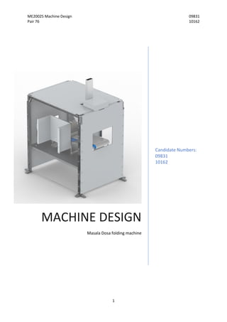
This design process focused upon the development of a masala dosa folding machine. The main
functions are transportation through the machine, filling the dosa, folding and pressing. A
morphological chart and three concepts were created and evaluated. A final design was created and
it was evaluated further in terms of cost, reliability and food safety.
Table of Contents
1. Introduction
1.1 Problem Overview
1.2 Requirements Specification
1.3 Approach to Analysis
2. Concept Design
2.1 Design Alternatives
2.2 Food safety
2.3 Concepts
2.4 Evaluation and selection
3. Design
3.1 Design Analysis and Development
3.1.1 Angle of slip
3.1.2 Torque Analysis
3.1.3 Shaft Analysis and Bearing selection
3.2 Incorporated Food Safety Features
3.3 Manufacturing/Material selection
3.3.1 Shaft
3.3.2 Roll block
3.3.3 Frame
3.3.4 Outsourced components
3.4 Assembly
3.5 Maintenance
3.6 Mode of operation
3.7 Operating sequence
3.8 Reliability analysis
3.9 Operational energy use
3.10 Costs
3.11 Design evaluation
4. Solution Specification
5. Conclusion
6. References
Appendix
3. ME20025 Machine Design 09831
Pair 76 10162
3
1. Introduction
1.1 Problem Overview
The project focused upon designing a masala dosa filling and folding machine. The functions of
which included filling the dosa pancake before rolling or folding it and then pressing it to enforce the
folds. The machine would be used in commercial industry to sell frozen masala dosas in large
quantities. The machine would need to automatically produce a masala dosa and would fold one
dosa in one cycle, which was specified to take 25 seconds.
1.2 Requirements Specification
D/W Wt Requirements Keyword Date
D
D
D
D
D
Geometry:
- Maximum height of machine is 2.5m
- Filling is 150x60x20mm
- Stated Weight
- Masala Dosa has a diameter of
300±10mm
- Footprint of 2 x 1.5m
Height
Filling size
Weight
Diameter
Footprint
10/02/17
10/02/17
10/02/17
10/02/17
10/02/17
D
D
D
D
D
D
D
Operation:
- 2 folds
- Include filling in Dosa
- 25 seconds per dosa
- Machine operating for 8hrs/day
- 10 years’ lifetime
- The operator should be able to load the
machine with the filling, but then the
machine is fully automated
- ‘Hold’ mechanism to seal the dosa
Folds
Filling
Time/Dosa
Machine operating
Lifetime
Automatic
Hold mechanism
10/02/17
10/02/17
10/02/17
10/02/17
10/02/17
10/02/17
10/02/17
D
Forces:
- Coefficient of friction between dosa
pancake and filling small enough so that
filling does not slide out of the pancake
whilst being rolled.
Friction 21/02/17
D
D
Energy:
- Run for 8hrs/day
- Machine powered by the mains, single
phase with 6 Bar air supply
Energy/Day
Power
10/02/17
10/02/17
D
W
D
3
Materials:
- Food safe machinery
- Use cheap and have limited wastage of
material whilst maintaining strength
- 24 frozen blocks of filling
Food safe
Wastage/Cost
Filling
10/02/17
10/02/17
10/02/17
D
W 2
Safety:
- Operational noise less than 100dB
- Operational noise less than 85Db
Noise
Noise
10/02/17
10/02/17
W
W
2
2
Sustainability/Environment:
- Energy efficient
- Sustainable materials
Efficiency
Materials
10/02/17
10/02/17
4. ME20025 Machine Design 09831
Pair 76 10162
4
D
W 3
Economics:
- Sold for £8-10 000
- Manufacturing cost significantly less
Price
Cost
10/02/17
10/02/17
D
W 3
Production/Assembly:
- 10 Manufactured in total
- Easy to assemble
Units
Assembly
10/02/17
10/02/17
W
W
3
3
Maintenance:
- Easy to maintain
- Easy to clean
Maintenance
Clean
10/02/17
10/02/17
Table 1.2.1 shows the Requirements Specification created for this design brief.
1.3 Approach to Analysis
Figure 1.3.1 shows the flow diagram of the process taken in this design project.
5. ME20025 Machine Design 09831
Pair 76 10162
5
Figure 1.3.2 shows a function diagram of the machine design, including the inputs and outputs of the system.
Figure 1.3.1 shows the flow diagram used to evaluate and carry out this design process. Figure 1.3.2 shows the function design created for the machine as
detailed in the design brief provided.
6. ME20025 Machine Design 09831
Pair 76 10162
6
2. Concept Design
2.1 Design Alternatives
The first step to addressing this brief, once the requirements specification had been established, was
to develop a morphological chart. The brief was split into the different functions of the machine:
folding, pressing, filling and transporting the masala dosa. Various ways of achieving each function
were then developed. The morphological chart can be seen in Figure 2.1.1. The coloured arrows
show the different pathways that were combined to create three concepts for this brief.
Figure 2.1.1 shows the morphological chart and pathways used to create the concept drawings.
2.2 Food safety
When designing a machine to be used with food, it is of vital importance to address and explore the
methods of creating a hygienic and food safe machine. Under EU regulations, companies are forced
to ensure there are quality control system to ensure a standard of food safety is met (1). There are
numerous rules which need to be followed to ensure hygienic food production facilities:
- Machine materials must be able to be cleaned before use, to a microbiological level
- Machines must be able to be inspected, maintained and cleaned
- All surfaces must be smooth, without ridges or crevices
- There should be minimal projections, edges and recesses
- The surfaces that are in contact with the food must be easily cleaned
- Machines should be constructed so that the food production is safe from liquids, animals,
soil, etc in areas that cannot be cleaned
- No lubricants or any other additional substances come into contact with the food
- Machine should be made of compatible materials (1)
Therefore, when creating concepts, it was important to evaluate the hygiene rules to ensure none
were being violated. It is also important that the materials in contact with the food are non-toxic
and will not transfer harmful chemicals to the food. Materials which are food safe are: plastic, paper,
metal and rubber (2). Metals such as stainless steel can be safely used as there are no chemicals
which can transfer from the metal to the food (3).
7. ME20025 Machine Design 09831
Pair 76 10162
7
Figure 2.1.1 shows the morphological chart and pathways used to create the three concept drawings shown in Section 2.3. This can also be seen in
Appendix 9.
Key
Concept 1
Concept 2
Concept 3
8. ME20025 Machine Design 09831
Pair 76 10162
8
2.3 Concepts
Figure 2.3.1 show Concept 1 which was developed from Figure 2.1.1. The pathway is in green.
Concept 2 is shown in Figure 2.3.2. The pathway of this concept is in blue.
Figure 2.3.3 shows Concept 3 which was developed from Figure 2.1.1. The pathway is in orange.
2.4 Evaluation and selection
Criteria Weighting 2 1 3
Score Wt Sc Score Wt Sc Score Wt Sc
Weight 2
Datum
-2 -4 1 2
Dimensions/Size 3 -1 -3 0 0
Ease of
operation
3 -1 -3 0 0
Ease of refilling 1 1 1 0 0
Materials
(efficient/cheap)
3 0 0 0 0
Noise, less than
85dB
2 0 0 1 2
Energy efficient 2 -1 -2 1 2
Sustainable
materials
2 0 0 0 0
Manufacturing
cost low
3 -2 -6 1 3
Easy to
assemble
3 -1 -3 0 0
Easy to
maintain/clean
3 -2 -6 1 3
0 -26 12
Table 2.4.1 shows the Pugh matrix with a five-point scale system, used to evaluate the three concept
designs shown in Section 2.3.
From Table 2.4.1, Concept 3 scored the highest overall, this was due to a simplified process and
including fewer moving parts. This suggested that it would be easier to maintain and repair than the
other concepts. It would also have lower manufacturing costs due to the limited number of parts.
Concept 1 on the other hand, scored significantly lower, despite a thorough idea. This concept was
relatively complex and required a lot of moving parts. The dosa would also be exposed to gears
which could cause problems with regards to food safety and to the fundamental operation of the
machine. Therefore, considering the Pugh matrix, it was decided to develop Concept 3 as the final
design.
9. ME20025 Machine Design 09831
Pair 76 10162
9
Figure 2.4.1 shows the final design, with and without the guards.
10. ME20025 Machine Design 09831
Pair 76 10162
10
3. Design
3.1 Design Analysis and Development
3.1.1 Angle of slip
After deciding to use a roll block to force the dosa pancake to roll against itself, it was decided to
conduct an experiment to determine approximate slip angles between the dosa pancake and the
conveyor belt, as seen in Figure 3.1.1.1. The angle of slip between the dosa pancake and frozen
filling was also determined, as can be seen in Figure 3.1.1.2. The angles of slip found can be seen in
Table 3.1.1.1.
Figure 3.1.1.1 shows the experimental set up used to determine the angle of slip.
Figure 3.1.1.2 shows the experiment which determined the angle of slip between the dosa pancake
and the filling.
11. ME20025 Machine Design 09831
Pair 76 10162
11
Materials Angle (degrees)
Dosa and filling 5
Dosa and conveyor belt 40
Table 3.1.1.1 shows the angles of slip which were experimentally determined.
Many assumptions were made in this experiment:
- That the filling can be modelled by ice, assuming the relative density is 1.
- That the filling can be modelled by a block of ice with dimensions 165 x 70 x 40, which is
larger than the stated filling size, this can be seen in Figure 3.1.1.3
- The surface of the conveyor belt can be modelled by cardboard
- The masala dosa pancake can be modelled using a tortilla wrap
Figure 3.1.1.3 shows the block of ice used to model the masala dosa filling.
Several problems were encountered in this experimental set up, one being that the measuring
system was not very precise. It was difficult to accurately measure the angle of the cardboard, it
would only have been accurate to ±1°. The cardboard was often not at the same angle consistently
along the ‘belt’ so determining the actual angle of slip was challenging. In addition, the block of ice
used to model the filling began to thaw during the experiment which caused the cardboard to
dampen, which would have altered the surface texture of it leading to inconsistent results.
12. ME20025 Machine Design 09831
Pair 76 10162
12
3.1.2 Torque Analysis
The camshaft in the cam system needed to be analysed to determine the correct shaft size. The
cams on the camshaft needed to raise the rolling block to top dead centre and back to its lowest
position (1 full rotation). The torque required for this was found using Tdθ = mg dx + µN dp.
T = Torque, θ = Angle of rotation, mg = Weight of the block, x = Linear upward block motion, µ =
Coefficient of friction, N = Normal reaction on block and p = Perimeter distance of cam.
Mg and µN represent the weight of the block and total friction between the block and the cams
respectively. The normal reaction exerted by the cams equates to the weight of the block. Therefore,
the equation can be simplified to Tdθ = mg dx + µmg dp.
For simplicity, the cams were modelled as circles with radius 40mm and a gradual radius increase of
30mm. The max distance from the centre of the cams were 70mm as shown in Figure 3.1.2.1. To
calculate the total perimeter of the cam, the radius was assumed constant over π/8. Trigonometry
was used to find the perimeter by splitting the section into two triangles. The outer distance of these
triangles was added to ¾ of the perimeter for a 40mm radius circle. The calculation, Perimeter of
cam = 2 x outer triangle edges + ¾ x perimeter of 40mm radius circle = 0.287m, is shown in Appendix
1.
Figure 3.1.2.1. shows the cam design.
Table 3.1.2.1 shows the constants required for this torque calculation. Only the rotational portion of
the cams that exerted torque on the block to raise it up needed to be considered. As the torque is
exerted over π/2 radians, this angle of rotation will be used.
Constant Quantity
Angle of rotation, θ π/2 rads
Block mass, m 73kg
Gravitational acceleration, g 9.81m/s2
Vertical linear block displacement, x 30mm
Cam perimeter distance, p 0.287m
Table 3.1.2.1 shows the constants used in the torque calculations.
Appendix 2 shows that the Torque required over 1 cycle equals 73.1Nm.
13. ME20025 Machine Design 09831
Pair 76 10162
13
Next, the shaft rotational speed was determined. As the block was being raised and lowered once
for every dosa, the cams must rotate by one revolution for each dosa. As one dosa was being passed
through the machine every 25 seconds: 60/25 = 2.4 dosas are being passed through each minute.
Therefore, the camshaft must rotate at a speed of 2.4rev/min while supplying a minimum total
torque of 73.1Nm to the cams. The component which provided both low rotational speed and a
considerable amount of output torque as well as compatibility with a 230V input, was a Panasonic
M91Z60G4GGA geared motor was used, as shown in Figure 3.1.2.2.
Figure 3.1.2.2 shows the specification of the motor chosen for the camshaft.
The integrated gear ratio of 120:1 was chosen, the speed was reduced from 1300rpm to 10.83 rpm.
The output torque converged to 19.6Nm for the high integrated gear ratios. A gear ratio of 4.5 was
required to reduce the speed to 2.4rpm whilst increasing the torque above the requirement of
73.1Nm. Therefore, an external gear ratio was used. A spur gear transmission was chosen for
simplicity as the gear ratio was not large enough to consider planetary or worm gears. The 4.5 speed
ratio gave an output torque of 88.2Nm, which was a considerable amount of torque clearance to
supply to the cams. HPC PG4-14 and HPC PG4-63 were chosen for this transmission as they provided
a large diameter bore for the cam shaft. The calculations used to choose the motor and gears are
shown in Appendix 3.
3.1.3 Shaft analysis and Bearing selection
A camshaft was designed with the constraints of having to hold the PG4-63 gear and having 20mm
diameter on each end to fit the two cams. Table 3.1.3.1 shows the constants used.
Constants Quantity
Weight of rolling block, W 716N
Shaft diameter at cams 20mm
Shaft diameter at driven gear 30mm
Torque supplied by driven gear 88.2Nm
Table 3.1.3.1 shows the constants used in the camshaft analysis.
14. ME20025 Machine Design 09831
Pair 76 10162
14
Firstly, a free body diagram was constructed to simplify the problem. Only vertical forces were
considered as there were no forces acting in the horizontal direction, this can be seen in Figure
3.1.3.1.
Figure 3.1.3.1 shows the free body diagram of the camshaft.
Shear force and bending moment graphs were then plotted to show where the maximum bending
moments and shear forces would act on the shaft, these can be seen in Figure 3.1.3.2. A torque
diagram can be seen in Figure 3.1.3.3.
Figure 3.1.3.2 shows the shear force and bending moments diagrams for the camshaft analysis.
15. ME20025 Machine Design 09831
Pair 76 10162
15
Figure 3.1.3.3 shows the torque diagram for the shaft analysis.
The nodes along the shaft were then established. These are chosen locations which are susceptible
to high shear force or bending moment, such as at the centre of bearings and the cams; or which
contain a considerable amount of stress concentration, such as at shoulders. Table 3.1.3.2 shows the
locations of the nodes.
Nodes Locations
1, 11 Centre of cam
2, 4, 5, 6, 8, 10 Shoulder
3, 9 Centre of bearings
7 Centre of cam gear
Table 3.1.3.2 shows the nodes and locations for the shaft analysis.
Design and safety factors were also established. The constituting factors are shown in Appendix 4
with justification, while the design factors at each node are shown in the iteration spreadsheets. The
main factors included: Fatigue factor = 1.5, Shock factor = 1, Safety factor = 2.145. An initial shaft
design can be seen in Figure 3.1.3.4.
Figure 3.1.3.4 shows the initial shaft design for the camshaft with the numbered nodes shown.
16. ME20025 Machine Design 09831
Pair 76 10162
16
Iteration 1
Initially, the cams were designed with bores of 15mm while the cam gear was chosen to have a bore
of 25mm. This was done to minimise material and subsequently cost where possible. One such shaft
configuration which satisfied these parameters is shown in Figure 3.1.3.4.
Figure 3.1.3.5 shows the first iteration table generated.
The stress analysis table in Figure 3.1.3.5 shows that at several nodes, most notably around the
bearings, the allowable stress for the two stainless steel materials were lower than the combined
stress. The stainless-steel materials would not be able to accommodate the stress and would fail.
The shaft could be made thicker in those locations, fillet radii could be made larger to reduce stress
concentration or the torque or bending forces could be reduced, to combat this. The most feasible
solution was to increase the thickness of the shaft at those locations. Increasing these quantities
reduced both the bending stress and torsional stress as shown in Appendix 5.
Iteration 2
Many of the shaft cross-sections were made larger as shown in Figure 3.1.3.6. This caused the
allowable stresses on both stainless-steel materials to be above the combined stress and thus both
could be used. This shaft design was taken forward to the next stage, the final shaft design can be
seen in Figure 3.1.3.7. The cams were modified and the gears and bearings were chosen. AISI 1018
mild steel was chosen as the final shaft material.
17. ME20025 Machine Design 09831
Pair 76 10162
17
Figure 3.1.3.6 shows the final iteration table for the shaft analysis.
Figure 3.1.3.7 shows the final camshaft design.
Bearing Selection
Two parameters constrained the selection of bearings: the minimum lifetime and the bore of the
bearing. It was calculated that the bearing lifetime would be 4.2 million cycles for 10 years of
operation and the established shaft diameter through the bearings was 30mm. In addition, it was
desirable for the bearings to be compatible with a housing component which could be bought. In
this case, the static and dynamic loading was not a significant factor in bearing selection as both
values were particularly low with applied load, p =358N and dynamic load, C = 578N. To satisfy the
requirements, SKF 2306K bearings were chosen as well as the SE 507-606 housing which can be
bolted at its flanges to a flat surface. All bearing calculations are shown in Appendix 6.
18. ME20025 Machine Design 09831
Pair 76 10162
18
Keyways and bore reducer
Keyways were implemented for both the driving gear at the cam motor shaft and for the driven gear
on the cam shaft. The keyway calculations are shown in Appendix 7. To enable the driving gear with
a bore diameter of 25mm to fit onto the motor shaft with a shaft diameter of 15mm, a bore reducer
was added. This also increased the length of the motor shaft, allowing the driving gear bore to be in
full contact on the shaft. Interference fits between all interfaces have been chosen.
Conveyor belt motor
The main constraint on the conveyor speed was the rolling time. As the pancake rolling takes ⅜ of
the cam rotation (half of the time where rolling block is at lowest position), the rolling can be shown
to take 9.375s. Therefore, 300mm of distance must be covered (diameter of dosa) in 9.375s. This
dictates a speed of 0.032m/s on the conveyor and thus a rotational velocity of 6.11rpm in the
conveyor motor and driving roller. To provide this rotational speed, a Crouzet 80 547 016 motor was
chosen. Although this motor has an output speed of 9rpm, the speed can be controlled via a control
system in the black box to maintain the rotation as close to 6.11rpm as possible. Associated
calculations are shown in Appendix 8.
3.2 Incorporated Safety Features
It was decided after choosing the concept to include guarding in the structure of the framework. This
was for numerous reasons, one being that it would stop contaminants from entering the machines
system and coming into contact with the food. The guards also serve the other purpose of protecting
the user or operator from the working machine. In addition, all materials chosen for the machine
were either stainless steel or aluminium. These materials are suitable as they do not contain any
chemicals that would contaminate the food. Also, the machine is relatively simple to assemble,
meaning that the individuals pieces can be removed and cleaned easily. For instance, the conveyor
belt can be removed easily by removing the circlips form the roller shaft, and then taken off the
rollers. It could then be easily cleaned as it is made of rubber.
To further improve the safety aspects of this design, interlocking guards could be used to ensure that
the machine is only operational when they are closed fully (4). In addition, an emergency stop
system could also be incorporated to further improve the safety and control of the operator (5). This
could be achieved by having the emergency stop remove power to the machine, so all functions
cease immediately.
19. ME20025 Machine Design 09831
Pair 76 10162
19
3.3 Manufacturing and Material selection
3.3.1 Shaft
The camshaft in the cam system was chosen to be made from stainless steel. This was due to food
safety. One method of manufacturing the shaft would be using closed die forging. Two dies are used
to force the raw material into the desired shape, this can be seen in Figure 3.3.1.1.
Figure 3.3.1.1 shows the process of closed die forging (6).
This process can produce complicated shapes and can provide small tolerances (7), both which can
be useful especially with a part such as the camshaft which is vital to the function of the machine.
After being forged, the shaft would need to be machined to improve its surface finish.
3.3.2 Roll block
The roll block which the dosa is forced to roll against is made from aluminium. This could be
manufactured by sand casting. This process is ideal for low volume production rates. A pattern of the
part is pressed into moulding sand, it is then removed leaving an indentation of the required part in
the sand. Cores are used to create the correct internal structure for the part. The metal is then
poured into the sand mould and it solidifies. The sand is then removed from the casting (8). The roll
block would then need to machined to improve the surface finish of the part. The process of sand
casting can be seen in Figure 3.3.2.1.
Figure 3.3.2.1 shows the mould used in sand casting (9).
20. ME20025 Machine Design 09831
Pair 76 10162
20
3.3.3 Frame
The frame of the machine consists of four main components: two sides, a middle platform and a top
platform. These are made from stainless steel and could be manufactured by open die forging. This
process allows large parts to be made, and can produce many different types of parts (7). The
process consists of the material being compressed between dies, moved and then compressed again
(10). This can be seen in Figure 3.3.3.1. The part would then need to be machined and also drilled to
ensure the holes required for screws are present, some of which may need to be tapped.
Figure 3.3.3.1 shows the process of open die forging (11).
3.3.4 Outsourced components
Component Description Source
M10 x 50 bolt Zinc plated steel Screwfix
M10 x 90 bolt Stainless steel Screwfix
M16 x 90 bolt Stainless steel ACCU Group
M10 nut Zinc plated steel Screwfix
M16 nut Zinc plated steel Screwfix
M10 washer - Screwfix
Circlip ID 8.4mm Stainless Steel ACCU Group
Scotch yoke
motor
Crouzet Synchronous AC Geared Motor, Clockwise, 230 V
ac, 2.4 rpm, 3.5 W (12)
RS Components
Camshaft motor Panasonic M91 Reversible Induction AC Motor, 60 W, 1
Phase, 4 Pole, 230 V ac (13)
RS Components
21. ME20025 Machine Design 09831
Pair 76 10162
21
Conveyor motor Crouzet Synchronous AC Geared Motor, Reversible, 230 V
ac, 9 rpm, 7.2 W (14)
RS components
Bearings Self-aligning ball bearings (15) SKF
Bearing housing Split plummer block housings, SNL and SE series for
bearings on an adapter sleeve, with standard seals (16)
SKF
Sensor Through beam photoelectric sensor connected to the black
box
Fargo controls
Table 3.3.4.1 shows the outsourced components selected for this machine design.
3.4 Assembly
Step Brief description
1 Assemble the frame sides and the middle platform using M10 x 60 and M10 x 90.
2 Place the conveyor roller supports and conveyor motor support and attach to the
middle platform using M10 x 90.
3 Assemble shaft sub-assembly, mesh the gears and press the cams on the ends of the
camshaft.
4 Using M10 x 90 attach the shaft sub-assembly to the middle platform, ensuring the
motor is in correct location.
5 Press fit roller shafts into rollers, and the roller motor shaft into the third roller.
6 Place motor, rollers and conveyor belt in location and secure using circlips. Ensure
wires are safely placed/positioned so can be connected to the black box.
7 Attach roll block to guard rail and place in position.
8 Attach top frame platform using M10 x 60.
9 Join dispenser and motor support to frame using M10 x 60 and M10 x 90.
10 Press fit dispenser motor shaft onto scotch yoke wheel.
11 Assemble scotch yoke and dispenser mechanism.
12 Place dispenser mechanism in location.
13 Place black box in location, ensure wires are safely gathered.
14 Place filling cartridge in the dispenser.
Table 3.4.1 shows a brief assembly sequence of the Masala Dosa folding machine.
22. ME20025 Machine Design 09831
Pair 76 10162
22
3.5 Maintenance
Component Maintenance
Motors All motors used may need to be replaces, as well as being
maintained. If excessive heat or noise is observed, should be
thoroughly checked, otherwise minimal maintenance is required.
Conveyor belt The conveyor belt will need to be regularly checked for wear, as well
as routinely cleaned. The dosa pancake and filling may leave residue
that could lead to jams in the rollers. Lubrication would be needed on
the rollers to ensure a smooth continuous movement.
Scotch yoke mechanism Should be checked for wear between motor shaft and scotch yoke
wheel as this could cause mechanism to no longer work. Lubrication
may be needed between the wheel and the mechanism to ensure
smooth release of filling.
Gears Lubrication may be needed. In addition, should be regularly checked
for wear or teeth damage. Should be semi-regularly checked to
ensure correct alignment between teeth.
Cams Brief inspections should be carried out to ensure no cracks or fatigue
in cams due to roll block weight. May need to be replaced if cracks or
significant wear are observed.
Bearings The camshaft bearings should be checked to ensure no excessive
wear or damage has sustained them. There should be minimal heat
generation, meaning minimal maintenance requirements.
Table 3.5.1 shows the various components in the machine and the required maintenance for each.
3.6 Mode of operation
1 One pancake every 25 seconds travels
on an inclined conveyor and drops onto
the machine conveyor. There is a gap in
the front panel to allow the pancakes to
enter.
23. ME20025 Machine Design 09831
Pair 76 10162
23
2 A cartridge housing on top of the
machine stores 24 dosa fillings to be
dropped onto the dosa pancakes on the
conveyor.
3 A scotch yoke mechanism operating at
2.4rpm pushes out a dispenser unit.
This dispenser unit stores one filling in
its gap and when it is at its position in
the image, a gap on the platform allows
the filling to drop onto the conveyor.
This is timed such that one drops every
25 seconds. In addition, a through beam
photoelectric sensor is used to identify
when the dosa pancake is on the right
position on the conveyor belt. This is
connected to a black box which controls
the three motors. When the sensor has
been activated, the three motors turn
on for 25 seconds.
4 The conveyor motor powering the
conveyor belt rotates at 6.11 rpm after
being turned on. This speed is
maintained by a control system in the
black box and is specifically rotated at
this value to move the unfolded
pancake and filling towards the rolling
block at a speed of 0.032m/s.
5 The cam motor is also timed to operate
at a speed of 2.4rpm and transfers a
torque of 88.2Nm to the cam shaft.
24. ME20025 Machine Design 09831
Pair 76 10162
24
6 This cam shaft raises the rolling block,
via two cams, a vertical distance of
30mm. The roll block rolls the dosa,
when it is at its lowest position, for
9.375 seconds. The dosa drops onto the
conveyor when the block is at top dead
centre for 3.125 seconds. The conveyor
moves the dosa under the rolling block
to press it for 12.5 seconds. The rolling
block is supported by 4 linear rail guides
which are attached to the walls of the
machine housing. These rail guides
ensure that the rolling block only moves
in the vertical direction and does not
tilt.
7 The folded and pressed dosa then
emerges from the back side of the
machine through a gap in the back
panel.
Table 3.6.1 shows the mode of operation of this design.
25. ME20025 Machine Design 09831
Pair 76 10162
25
Figure 3.6.1 shows the final rendered design.
3.7 Operating sequence
Figure 3.7.1 shows the timing diagram for this design. A represents the through beam photoelectric
sensor which is controlled by the black box. This sensor identifies that the dosa pancake is present
on the conveyor belt which causes all three motors to start. B, C and D represent the dispenser
motor, conveyor motor and camshaft motor respectively. On this diagram, 1 is equivalent to 2
seconds. The entire process per dosa takes 25 seconds.
26. ME20025 Machine Design 09831
Pair 76 10162
26
3.8 Reliability study
Table 3.8.1 shows the reliability evaluation of the design.
27. ME20025 Machine Design 09831
Pair 76 10162
27
Figure 3.8.1 shows the fault tree for the Masala Dosa machine design.
28. ME20025 Machine Design 09831
Pair 76 10162
28
3.9 Operational energy use
General Information
Machining scenario Masala Dosa Folding Machine
Machine lifetime 10 years
Functional unit – No. of working hours/year 2920 hours
Energy Requirements
Black box 500W = 0.5kW
Rolling operation 60W = 0.06kW
Dispenser mechanism 3.5W = 0.0035kW
Conveyor belt 7.2 W = 0.0072kW
Time breakdown in s/cycle
Black box 25s/cycle (100%)
Rolling operation 9.375s/cycle (37.5%)
Dispenser mechanism 25s/cycle (100%)
Conveyor belt 25s/cycle (100%)
Time breakdown in hours
Black box 2920hrs
Rolling operation 1090hrs
Dispenser mechanism 2920hrs
Conveyor belt 2920hrs
Energy use
Black box 1460kWh
Rolling operation 65.4kWh
Dispenser mechanism 10.22kWh
Conveyor belt 21.024kWh
Total energy use per year 1556.644kWh
Total energy use per machine lifetime 15,566.44 kWh
Tables 3.9.1 – 3.9.5 show the operational energy use of the masala dosa folding machine. The total
energy use per lifetime was found to be 15,566.44 kWh. This was using the assumption that the
black box power rating was 500W, and the maximum motor power ratings were used.
29. ME20025 Machine Design 09831
Pair 76 10162
29
3.10 Costs
Table 3.10.1 shows the cost estimates for this design. All manufacturing process costs were
approximately determined. To further reduce the cost of this machine, alternative materials could
be considered, in addition to cheaper manufacturing processes. The overall total cost was found to
be £5200.
30. ME20025 Machine Design 09831
Pair 76 10162
30
Table 3.10.1 shows the cost estimate for this design. These are approximate values, and some parts
which were initially thought to be manufactured have been assumed to be purchased from
suppliers, such as the conveyor belt. This would be a more cost effective and could be further
applied to the remaining parts to decrease the total cost of the design.
3.11 Design evaluation
The created design has many positive aspects, one being that the method of rolling/folding the dosa
is relatively simple. However, it relies heavily upon the timing and synchronisation of the three
motors to ensure the masala dosa is rolled correctly. The black box and sensor used would have to
be accurate to ensure this. There are also many ways in which this design could be improved. One
being to add to the safety features already present. Including an emergency stop and changing the
guards to interlocking guards would increase the safety of the user. In addition, further research into
food safe practices could be carried out to further increase the hygiene and food safety of the
machine. Also, buying in framework from a supplier rather than manufacturing it would be more
cost effective and simpler. In addition, to improve ease of assembly the bolts used could be of the
same thread and length.
4. Solution Specification
- Entire folding and filling process takes 25 seconds
- Rolling process takes 9.375s
- 15566.44kWh a lifetime for the machine
- Powered by three motors connected to a black box, a Crouzet Synchronous AC Geared
Motor 3.5 W, Panasonic M91 Reversible Induction AC Motor 60 W and a Crouzet
Synchronous AC Geared Motor 7.2 W
- Through beam photoelectric sensor connected to the black box
- Footprint 2m x 1.5m
- Height 2.5m
- Total cost of £5200
- Retail price £8-10 000
- 230V, 50Hz power supply (mains)
31. ME20025 Machine Design 09831
Pair 76 10162
31
Figure 4.1 shows the final rendered design, as described in the above solution specification.
5. Conclusion
The final design, as seen in Section 4, met many of the requirements of this design brief. However,
there are many improvements which could be made to further increase the safety of the machine, in
terms of food safety but also in terms of general safety for the user. The dimensions of the finished
design met the design requirements, as did the time taken per dosa. However, this design relies
heavily upon synchronisation, meaning a black box was necessary. To further simplify the solution,
fewer motors could be used to simplify the design further. The frames could also be made smaller to
reduce material used.
As the batch size is low, sand casting was chosen to manufacture the roll block. Closed die forging
was used to manufacture the camshaft, and open die forging was chosen for the framework.
However, buying in the framework from a supplier such as ITEM 24 would have been easier. Guards
would also be able to be bought in.
Overall, the design met most of the requirement specification. However, certain aspects could be
altered to generally improve the function and safety of the machine.
32. ME20025 Machine Design 09831
Pair 76 10162
32
6. References
(1) Maguire, E., n.d. Hygeine Design requirements for Food processing machinery. [Online]
Available at:
https://moodle.bath.ac.uk/pluginfile.php/1032055/mod_resource/content/1/Hygienic%20d
esign%20requirements%20for%20food%20processing%20machinery.pdf
[Accessed 17 03 21].
(2) European Food Safety Authority, n.d. [Online]
Available at: https://www.efsa.europa.eu/en/topics/topic/food-contact-materials
[Accessed 22 03 2017].
(3) Zeidler, T., n.d. Guide to Stainless Steel. [Online]
Available at: http://eatdrinkbetter.com/2011/10/18/guide-to-stainless-steel/
[Accessed 22 03 2017].
(4) Lockett, A., 2015. Infographic for Engineering Design: Interlocking Guards. [Online]
Available at:
https://moodle.bath.ac.uk/pluginfile.php/818063/mod_resource/content/1/Design%20for%
20Interlocking%20Guards%20Infographic%20v0%203.pdf
[Accessed 21 03 2017].
(5) Lockett, A., 2015. Infographic for Engineering Design: Emergency Stop. [Online]
Available at:
https://moodle.bath.ac.uk/pluginfile.php/818062/mod_resource/content/1/Design%20for%
20Emergency%20Stop%20Systems%20Infographic%20v0%203.pdf
[Accessed 21 03 2017].
(6) Brooks forging, n.d. Forging Processes. [Online]
Available at: http://www.brooksforgings.co.uk/content/forging-processes
[Accessed 22 03 2017].
(7) Forging Industry Association, n.d. Types of Forging Processes. [Online]
Available at: https://www.forging.org/types-of-forging-processes
[Accessed 21 03 2017].
(8) Metal Technologies, n.d. Sand Casting Explained. [Online]
Available at: http://www.metal-technologies.com/docs/default-
source/education/sandcasting.pdf?sfvrsn=6
[Accessed 21 03 2017].
(9) Anon., n.d. Metal casting diagram. [Online]
Available at: http://www.pixell.club/metal-casting-diagram/
[Accessed 21 03 2017].
(10)Compass & Anvil, n.d. Open & Closed Die Forging. [Online]
Available at: http://www.compass-anvil.com/closed-die-forging
[Accessed 22 03 2017].
33. ME20025 Machine Design 09831
Pair 76 10162
33
(11)Anon., n.d. Lecture 2: Forging. [Online]
Available at:
http://nptel.ac.in/courses/112107144/Metal%20Forming%20&%20Powder%20metallurgy/l
ecture2/lecture2.htm
[Accessed 22 03 2017].
(12)RS Components, n.d. Crouzet Synchronous AC Geared Motor, Clockwise, 230 V ac, 2.4 rpm,
3.5 W. [Online]
Available at: http://uk.rs-online.com/web/p/ac-geared-motors/1812848/
[Accessed 21 03 2017].
(13)RS Components, n.d. Panasonic M91 Reversible Induction AC Motor, 60 W, 1 Phase, 4 Pole,
230 V ac. [Online]
Available at: http://uk.rs-online.com/web/p/ac-motors/0424162/
[Accessed 22 03 2017]
(14)RS Components, n.d. Crouzet Synchronous AC Geared Motor, Reversible, 230 V ac, 9 rpm, 7.2
W. [Online]
Available at: http://uk.rs-online.com/web/p/ac-geared-motors/2044787/
[Accessed 22 03 2017]
(15)SKF, n.d. Self-aligning ball bearings. [Online]
Available at: http://www.skf.com/group/products/bearings-units-housings/ball-
bearings/self-aligning-ball-bearings/self-aligning-ball-
bearings/index.html?designation=2306%20K
[Accessed 21 03 2017]
(16)SKF, n.d. Split plummer block housings, SNL and SE series for bearings on an adapter sleeve,
with standard seals. [Online]
Available at: http://www.skf.com/group/products/bearings-units-housings/bearing-
housings/split-plummer-block-housings-snl-2-3-5-6-series/snl-se-series-adapter-sleeve-with-
standard-seals/index.html?designation=SE%20507-
606%20%2B%202306%20K%20%2B%20HA%202306
[Accessed 21 03 2017]
34. ME20025 Machine Design 09831
Pair 76 10162
34
Appendix
Appendix 1:
Cam perimeter = (2 x sin(45) x 0.07) + (¾ x 2pi x 0.04) = 0.287m
Appendix 2: Torque required by cams over 1 cycle:
T = (mg dx + µmg dp)/dθ
=(73 x 9.81 x 30E-3)/(pi/4) + (1.4 x 73 x 9.81 x 287E-3)/(2xpi)
= 73.1Nm
Appendix 3: Motor and transmission must provide a speed of 2.4rpm and a torque of over 73.1Nm.
Motor chosen: Panasonic M91Z60G4GGA with MY9G120B Flanged edition
Using 120:1 Speed ratio
Output omega = 1300rpm
With integrated 120:1 speed ratio: 1300/120 = 10.83rpm from motor
Torque = 19.6Nm from motor
10.83/2.4 = 4.5
Therefore a gear ratio of 4.5 is required to reduce the rotational speed to 2.4rpm
Final torque with 4.5 speed ratio: 19.6 x 4.5 = 88.2Nm > 73.1Nm
Therefore, 88.2/2 = 44.1Nm of torque transferred to each cam
Gears chosen:
Driving gear: HPC PG4-14 with PCD = 56mm and Bore D = 25mm
Driven gear: HPC PG4-63 with PCD = 252mm and Bore D = 30mm
252/56 = 4.5
Appendix 4 - Design and Safety Factors:
Design Factor, Ny = b x c x d x k
Fatigue Factor, b = 1.5 as there is alternating tension and compression in shaft
Shock Factor, c = 1 as load applied gradually over pi/4 angle. Not a high amount of loading.
For Safety Factor, d, Pugsley’s Method was used.
35. ME20025 Machine Design 09831
Pair 76 10162
35
d=X x Y
For X: A = Good, B = Good, C = Fair. Thus X = 1.95
For Y: D = Not Serious, E = Serious. Thus Y = 1.1
d=1.95 x 1.1 = 2.145
In summary: b = 1.5, c = 1, d = 2.145. K is dependent on fillet radii and concentration of stress at the
node.
Appendix 5 - Increasing diameter to reduce both bending and torsional stress
Bending Stress, σ = My/I
Where M = Bending moment, y = Distance from neutral axis and I = Second moment of area
Second moment of area of a shaft, I = (pi x d^4)/64
Therefore I is directly proportional to (diameter)^4 and σ is inversely proportional to (diameter)^4
Torsional Stress, τ = (T x r)/J
Where T = Torque, r = Radius and J = Polar second moment of area
Polar second moment of area of a shaft, J = (pi x d^4)/32
Therefore J is directly proportional to (diameter)^4 and τ is inversely proportional to (diameter)^4
Thus increasing diameter reduces both bending and torsional stress by a considerable amount -
specifically by a power of 4.
Appendix 6 - Bearing Selection
For SKF 2306K self-aligning ball bearing:
Working out minimum bearing life:
Life = 10 years, 8 hours/day, 25s/dosa
36. ME20025 Machine Design 09831
Pair 76 10162
36
(10 x 365 x 8 x 60 x 60)/25 = 4.2 million cycles
Main Bearing Equation: C = P x proot(L)
Where C = Dynamic load rating (kN), P = Applied load (N), p = 3 for ball bearings, L = Life time
(millions of cycles)
P = ½ x rolling block weight = 358N
Co = 8.8kN > P
Equivalent dynamic load rating, C = (358) x cuberoot(4.2) = 578N
578 < 23.4kN
As both static load and dynamic load ratings are satisfied, this bearing can be used.
Appendix 7 - Keyway calculations
1. For driving gear (on cam motor shaft)
Integrated width = 5mm, length = 25mm
For close and interference between 12mm and 17mm shaft diameter:
Height, h = 5
Key = 5mm x 5mm cross section with width = 5 -0.012 to -0.042 mm
3mm depth in shaft
2.3mm depth in hub
Length can be 10-56mm which was satisfied
Therefore, driving gear key = Square parallel key: 5 x 5 x 25
2. For driven gear (on camshaft)
For shaft diameter = 30mm, normal fit width = 8 +0.018 to -0.018 in hub
8 + 0 to -0.036 in shaft
Normal fit depth = 4 +0.2 to 0 in shaft
3.3 +0.2 to 0 in hub
Length, l can be 18-90mm, allowing 20mm length to be used
Therefore, driven gear key = Rectangular parallel key: 8 x 7 x 20
Appendix 8 - Conveyor belt motor
Rolling time = ¾ x ½ x 25s = 9.375s
Rolling requires a 300mm diameter pancake to be rolled in 9.375s
Therefore, conveyor speed = 300mm/9.375s = 32mm/s = 0.032m/s
37. ME20025 Machine Design 09831
Pair 76 10162
37
Conveyor belt roller perimeter = 2 x pi x 0.05m = pi/10 m
Rotational speed of belt roller = 0.032/(pi/10) = 0.10186 revolutions per second
0.10186 x 60 = 6.11rpm
Appendix 9 – Morphological chart