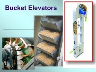
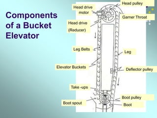
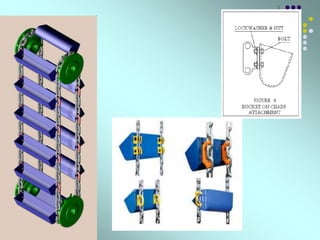
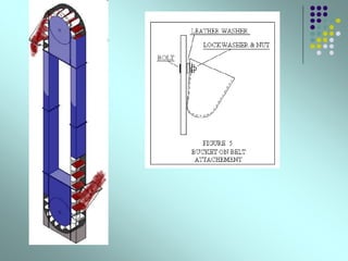
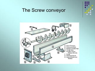
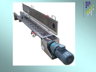
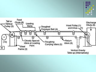
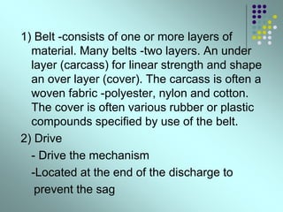
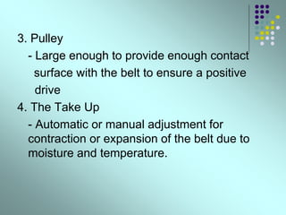
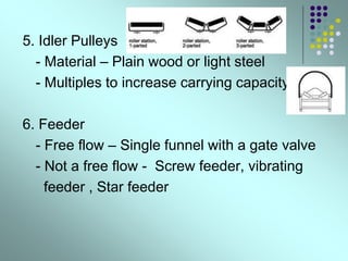
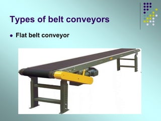
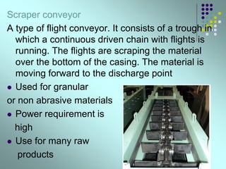
The document provides information on various types of conveyors used in material handling. It discusses belt conveyors, chain conveyors, scraper conveyors and bucket elevators in detail. Belt conveyors are very efficient and cause low damage to products. They are used for long distance conveying. Chain conveyors operate at slower speeds but cause more noise. Scraper conveyors use a trough and chain with flights to scrape materials along the bottom. Bucket elevators efficiently move materials vertically using buckets attached to a belt or chain. The document also provides equations to calculate conveyor design parameters such as belt tension, power requirements, and acceleration.


![The basics of the Calculations of
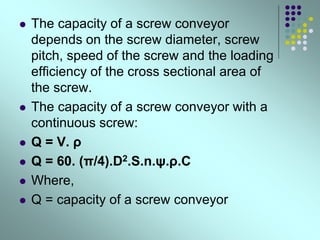
Conveyor Belt Design Parameters
Belt tension: The belt of the conveyor always
experience a tensile load due to the rotation of
the electric drive, weight of the conveyed
materials, and due to the idlers. The belt
tension at steady state can be calculated as:
Tb = 1.37*f*L*g*[2*mi+ (2*mb + mm)*cos (δ)]
+ (H*g*mm)…….eqn.1.1](https://image.slidesharecdn.com/conveyors-220722191718-1f03d276/85/CONVEYORS-ppt-24-320.jpg)
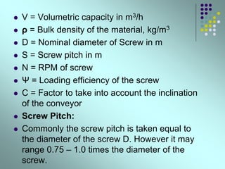
![ Acceleration :
The acceleration of the conveyor belt can be
calculated as:
A= (Tbs – Tb)/ [L*(2*mi + 2*mb+mm)]………eqn.1.6
Where,
A is in m/sec2
Tbs = the belt tension while starting in N.
Tb = the belt tension in steady state in N.
L = the length of the conveyor in meters.
mi = Load due to the idlers in kg/m.
mb = Load due to belt in kg/m.
mm = Load due to the conveyed materials in kg/m.](https://image.slidesharecdn.com/conveyors-220722191718-1f03d276/85/CONVEYORS-ppt-29-320.jpg)
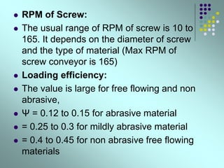
![ Tb = 1.37*0.02*250*9.81*[16.67+ {2*25+
(416.67/1.5)}*cos (5)] + (20*9.81* (416.67/1.5)) =
77556.88 N.
The belt tension while starting the system can be
calculated by using the eqn.1.4:
Tbs = 1.5 * 77556.88 = 116335.32 N
For calculating the power at drive pulley, we will use
the eqn.1.3:
Pp = (77556.88*1.5)/ 1000 = 116.335 kw
We will use the eqn.1.5 estimate the size of the motor:
Pm = 116.35/0.9 = 129.261 kw](https://image.slidesharecdn.com/conveyors-220722191718-1f03d276/85/CONVEYORS-ppt-32-320.jpg)
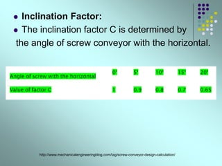
![ We will use the eqn.1.6 to find out the
acceleration of the motor:
A = (116335.32 - 77556.88)/
[250*{(2*16.67) + (2*25) + (416.67/1.5)}]
= 0.429 m/sec2](https://image.slidesharecdn.com/conveyors-220722191718-1f03d276/85/CONVEYORS-ppt-33-320.jpg)

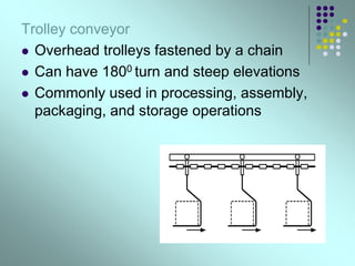
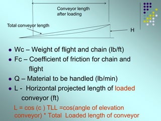
![Chain conveyor design
Generally flight speed – 75 -125ft/min
Capacity decreases with inclination
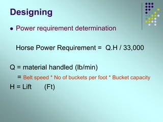
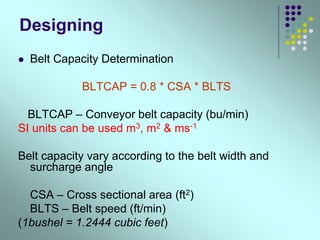
Horse power requirement
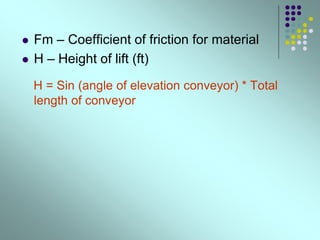
Horse power = 2* V *Lc* Wc* Fc + Q(L *Fm +H)
33000
V – Speed of the conveyor
Lc - Horizontal projection length of conveyor (ft)
Lc = cos ( c) * TCL
[ =cos(angle of elevation conveyor) * Total conveyor
length]](https://image.slidesharecdn.com/conveyors-220722191718-1f03d276/85/CONVEYORS-ppt-40-320.jpg)