SlideShare a Scribd company logo
1 of 21
NOTM
1. Compare and contrast the various unconventional machining process on the basis of
type of energy employed, material removal rate, transfer media and economical
aspects.
ANS: - The unconventional machining processes do not employ a conventional or traditional
tool for metal removal. Instead they directly utilize some form of energy for metal
machining. In this process there is no direct physical contact between the tool and
work piece.
ENERGY
TYPE
MATERIAL
REMOVAL
RATE
ENERGY
EMPLOYED
TRANSFER MEDIA
AND
ECONOMICAL
ASPECTS
PROCESS
Mechanical Plastic shear
erosion
Hydraulic pressure,
Pneumatic pressure
(Mechanical and fluid
motion)
High velocity particles AJM,
USM,
WJM,
AWJM
Electrochemical Ion displacement High current Electrolyte ECM
Mechanical and
Electrochemical
Ion
displacement,
Plastic shear
High current,
Mechanical motion
Electrolyte ECG
Chemical Vaporization,
Corrosive agent
corrosive agent Chemical CHEMICAL
MACHINUNG,
EDM
Thermal Vaporization Powerful radiation,
High speed electrons,
High voltage
Amplified coherent
light radiation,
Electron stream,
Ionized gas stream
LBM,
IBM,
PAM,
EBM
ENERGY SOURCE APPLIED
1. IBM – Ionized substance
2. CHM – corrosive agent
3. ECG – Electrical current and Mechanical motion
4. ECM – Electrical current
5. EDM – Electrical spark
6. EBM – High-speed electrons
7. AJM – Mechanical and fluid motion
8. LBM – Powerful Radiation.
Unconventional machining is classified according to major energy source as follows:
Thermal Energy methods: In this method, heat energy is concentrated on a small area
of the work piece to melt and vaporize tiny bits of work
material.
Examples: -
i) Laser beam machining
ii) Plasma Arc machining
iii) Electron beam machining
iv) Ion beam machining
Electrical energy methods: In this method, electrical energy is directly used to cut the
material to get the final shape and size.
Examples:
i) Electro Discharge machining(EDM)
ii) Wire cut EDM
Electro chemical energy methods: In this method, material is removed by ion
displacement of the work piece material in
contact with a chemical solution.
Examples:
i) Electro chemical machining
ii) Electrochemical grinding
iii) Electro chemical honing
iv) Electro chemical deburring
Chemical energy method: This method involves controlled etching of the work piece
material in contact with a chemical solution.
Example: Chemical machining
Mechanical energy methods: In this method, material is removed by mechanical erosion
of the work piece material.
Example: i) Ultrasonic machining
ii) Abrasive jet machining
iii) Water jet machining.
2. Explain the USM machine setup and discuss various feed mechanisms. Discuss the
influence process parameters and application.
ANS: -
Ultrasonic machining is a non-traditional machining process. USM is grouped under the
mechanical group NTM processes. In ultrasonic machining, a tool of desired shape
vibrates at an ultrasonic frequency (19 ~ 25 kHz) with an amplitude of around 15 – 50 μm
over the workpiece. Generally, the tool is pressed downward with a feed force, F. Between
the tool and workpiece, the machining zone is flooded with hard abrasive particles
generally, in the form of a water based slurry. As the tool vibrates over the workpiece, the
abrasive particles act as the indenters and indent both the work material and the tool. The
abrasive particles, as they indent, the work material, would remove the same, particularly
if the work material is brittle, due to crack initiation, propagation and brittle fracture of the
material. Hence, USM is mainly used for machining brittle materials {which are poor
conductors of electricity and thus cannot be processed by Electrochemical and Electro
discharge machining (ECM and EDM)}.
FEED MECHANISMS: -
1. Counter weight feed mechanisms
2. Spring loaded feed mechanisms
3. Pneumatic and hydraulic feed mechanisms
4. Electric solenoid control
5. Motor type etc.
Process Parameters and their Effects.
During discussion and analysis as presented in the previous section, the process parameters which
govern the ultrasonic machining process have been identified and the same are listed below along
with material parameters
• Amplitude of vibration (ao
) – 15 – 50 μm
• Frequency of vibration (f) – 19 – 25 kHz
• Feed force (F) – related to tool dimensions
• Feed pressure (p)
• Abrasive size – 15 μm – 150 μm
• Abrasive material – Al2
O3
- SiC
- B4
C
- Boronsilicarbide
- Diamond
• Flow strength of work material
• Flow strength of the tool material
• Contact area of the tool – A
• Volume concentration of abrasive in water slurry – C
MACHINE: -
The basic mechanical structure of an USM is very similar to a drill press.
However, it has additional features to carry out USM of brittle work material. The workpiece is
mounted on a vice, which can be located at the desired position under the tool using a 2 axis table.
The table can further be lowered or raised to accommodate work of different thickness.
1. Slurry delivery and return system
2. Feed mechanism to provide a downward feed force on the tool during machining
3. The transducer, which generates the ultrasonic vibration
4. The horn or concentrator, which mechanically amplifies the vibration to the required
amplitude of 15 – 50 μm and accommodates the tool at its tip.
The ultrasonic vibrations are produced by the transducer. The transducer is driven by suitable
signal generator followed by power amplifier. The transducer for USM works on the following
principle
• Piezoelectric effect
• Magnetostrictive effect
• Electrostrictive effect
Magnetostrictive transducers are most popular and robust amongst all. Typical
Magnetostrictive transducer along with horn. The horn or concentrator is a wave-guide,
which amplifies and concentrates the vibration to the tool from the transducer.
The horn or concentrator can be of different shape like
• Tapered or conical
• Exponential
• Stepped
Machining of tapered or stepped horn is much easier as compared to the
exponential one.
Applications
• Used for machining hard and brittle metallic alloys, semiconductors, glass, ceramics,
carbides etc.
• Used for machining round, square, irregular shaped holes and surface impressions.
• Machining, wire drawing, punching or small blanking dies.
Limitations
• Low MRR
• Rather high tool wear
• Low depth of hole
3. DEFINE ECM AND ALSO EXPLAINDYNAMIC OF ECM.
ANS: -
Electro Chemical Machining
Electrochemical Machining (ECM) is a non-traditional machining (NTM)
process belonging to Electrochemical category. ECM is opposite of
electrochemical or galvanic coating or deposition process. Thus ECM can
be thought of a controlled anodic dissolution at atomic level of the work
piece that is electrically conductive by a shaped tool due to flow of high
current at relatively low potential difference through an electrolyte which is
quite often water based neutral salt solution.
PROCESS: -
During ECM, there will be reactions occurring at the electrodes i.e. at the
anode or workpiece and at the cathode or the tool along with within the
electrolyte.
Let us take an example of machining of low carbon steel which is primarily a
ferrous alloy mainly containing iron. For electrochemical machining of steel,
generally, a neutral salt solution of sodium chloride (NaCl) is taken as the
electrolyte. The electrolyte and water undergoes ionic dissociation as shown
below as potential difference is applied
NaCl ↔ Na+ + Cl-
H2O ↔ H+ + (OH)-
As the potential difference is applied between the work piece (anode) and the
tool (cathode), the positive ions move towards the tool and negative ions
move towards the workpiece.
Thus the hydrogen ions will take away electrons from the cathode (tool) and
from hydrogen gas as:
2H+ + 2e- = H2 ↑ at cathode
Similarly, the iron atoms will come out of the anode (work
piece) as:
Fe = Fe+ + + 2e-
Within the electrolyte iron ions would combine with chloride ions to form iron
chloride and similarly sodium ions would combine with hydroxyl ions to form
sodium hydroxide
Na+ + OH- = NaOH
In practice FeCl2 and Fe(OH)2 would form and get precipitated in the form of
sludge. In this manner it can be noted that the work piece gets gradually
machined and gets precipitated as the sludge. Moreover, there is not coating
on the tool, only hydrogen gas evolves at the tool or cathode. Depicts
the electro-chemical reactions schematically. As the material removal takes
place due to atomic level dissociation, the machined surface is of excellent
surface finish and stress free.
The voltage is required to be applied for the electrochemical reaction to
proceed at a steady state. That voltage or potential difference is around 2 to
30 V. The applied potential difference, however, also overcomes the following
resistances or potential drops. They are:
• The electrode potential
• The activation over potential
• Ohmic potential drop
• Concentration over potential
• Ohmic resistance of electrolyte
EQUIPMENT
The electrochemical machining system has the following modules:
• Power supply
• Electrolyte filtration and delivery system
• Tool feed system
• Working tank
APPLICATIONS
ECM technique removes material by atomic level dissolution of the same by
electrochemical action. Thus the material removal rate or machining is not dependent
on the mechanical or physical properties of the work material. It only depends on the
atomic weight and valiancy of the work material and the condition that it should be
electrically conductive. Thus ECM can machine any electrically conductive work
material irrespective of their hardness, strength or even thermal properties. Moreover
as ECM leads to atomic level dissolution, the surface finish is excellent with almost
stress free machined surface and without any thermal damage.
ECM is used for
• Die sinking
• Profiling and contouring
• Trepanning
• Grinding
• Drilling
• Micro-machining
4. DEFINE EBM? DISCUSS ABOUT ITS EQUIPMENT SET UP AND PRINCIPLE
OF OPERATION.
ANS: -
ELECTRON BEAM MACHINING – PROCESS
Electron beam is generated in an electron beam gun. The construction and working
principle of the electron beam gun would be discussed in the next section. Electron beam
gun provides high velocity electrons over a very small spot size. Electron Beam Machining
is required to be carried out in vacuum. Otherwise the electrons would interact with the air
molecules, thus they would lose their energy and cutting ability. Thus the workpiece to be
machined is located under the electron beam and is kept under vacuum. The high-energy
focused electron beam is made to impinge on the workpiece with a spot size of 10 – 100
μm. The kinetic energy of the high velocity electrons is converted to heat energy as the
electrons strike the work material. Due to high power density instant melting and
vaporization starts and “melt – vaporization” front gradually progress, Finally the molten
material, if any at the top of the front, is expelled from the cutting zone by the high vapor
pressure at the lower part. Unlike in Electron Beam Welding, the gun in EBM is used in
pulsed mode. Holes can be drilled in thin sheets using a single pulse. For thicker plates,
multiple pulses would be required. Electron beam can also be manoeuvred using the
electromagnetic deflection coils for drilling holes of any shape.
ELECTRON BEAM MACHINING – EQUIPMENT
the schematic representation of an electron beam gun, which is the heart of any electron beam
machining facility. The basic functions of any electron beam gun are to generate free electrons at
the cathode, accelerate them to a sufficiently high velocity and to focus them over a small spot
size. Further, the beam needs to be manoeuvred if required by the gun.
The cathode as can be seen in Fig. 9.6.3 is generally made of tungsten or tantalum. Such
cathode filaments are heated, often inductively, to a temperature of around 2500
0
C. Such
heating leads to thermo-ionic emission of electrons, which is further enhanced by
maintaining very low vacuum within the chamber of the electron beam gun. Moreover, this
cathode cartridge is highly negatively biased so that the thermo-ionic electrons are strongly
repelled away from the cathode. This cathode is often in the form of a cartridge so that it
can be changed very quickly to reduce down time in case of failure.
Just after the cathode, there is an annular bias grid. A high negative bias is applied to this grid so
that the electrons generated by this cathode do not diverge and approach the next element, the
annular anode, in the form of a beam. The annular anode now attracts the electron beam and
gradually gets accelerated. As they leave the anode section, the electrons may achieve a velocity
as high as half the velocity of light.
ELECTRON BEAM PROCESS – PARAMETERS
The process parameters, which directly affect the machining characteristics in Electron Beam
Machining, are:
• The accelerating voltage
• The beam current
• Pulse duration
• Energy per pulse
• Power per pulse
• Lens current
• Spot size
• Power density
As has already been mentioned in EBM the gun is operated in pulse mode. This is achieved by
appropriately biasing the biased grid located just after the cathode. Switching pulses are given to
the bias grid so as to achieve pulse duration of as low as 50 μs to as long as 15 ms.
Beam current is directly related to the number of electrons emitted by the cathode or available in
the beam. Beam current once again can be as low as 200 μamp to 1 amp.
ELECTRON BEAM MACHINING – ADVANTAGES AND LIMITATIONS
EBM provides very high drilling rates when small holes with large aspect ratio are to be drilled.
Moreover, it can machine almost any material irrespective of their mechanical properties. As it
applies no mechanical cutting force, work holding and fixturing cost is very less. Further for the
same reason fragile and brittle materials can also be processed. The heat affected zone in EBM is
rather less due to shorter pulses. EBM can provide holes of any shape by combining beam
deflection using electromagnetic coils and the CNC table with high accuracy.
5. EXPLAIN THE PROCESS OF LBM AND PAM WITH A NEAT SKETCHS.
ANS: -
Laser Beam Machining – the lasing process
Lasing process describes the basic operation of laser, i.e. generation of coherent (both temporal
and spatial) beam of light by “light amplification” using “stimulated emission”.
In the model of atom, negatively charged electrons rotate around the positively charged nucleus in
some specified orbital paths. The geometry and radii of such orbital paths depend on a variety of
parameters like number of electrons, presence of neighboring atoms and their electron structure,
presence of electromagnetic field etc. Each of the orbital electrons is associated with unique energy
levels. At absolute zero temperature an atom is considered to be at ground level, when all the
electrons occupy their respective lowest potential energy. The electrons at ground state can be
excited to higher state of energy by absorbing energy form external sources like increase in
electronic vibration at elevated temperature, through chemical reaction as well as via absorbing
energy of the photon. Depicts schematically the absorption of a photon by an electron. The electron
moves from a lower energy level to a higher energy level.
On reaching the higher energy level, the electron reaches an unstable energy band. And it comes
back to its ground state within a very small time by releasing a photon. This is called spontaneous
emission. Schematically the same is shown in Fig. 9.6.7 and Fig. 9.6.8. The spontaneously emitted
photon would have the same frequency as that of the “exciting” photon.
Sometimes such change of energy state puts the electrons in a meta-stable energy band. Instead of
coming back to its ground state immediately (within tens of ns) it stays at the elevated energy state
for micro to milliseconds. In a material, if more number of electrons can be somehow pumped to
the higher meta-stable energy state as compared to number of atoms at ground state, then it is
called “population inversion”. Such electrons,
at higher energy meta-stable state, can return to the ground state in the form of an avalanche
provided stimulated by a photon of suitable frequency or energy. This is called stimulated
emission. Fig. 9.6.8 shows one such higher state electron in meta-stable orbit. If it is stimulated by
a photon of suitable energy then the electron will come down to the lower energy state and in turn
one original photon, another emitted photon by stimulation having some temporal and spatial
phase would be available. In this way coherent laser beam can be produced.
Fig. 9.6.9 schematically shows working of a laser. There is a gas in a cylindrical glass vessel. This
gas is called the lasing medium. One end of the glass is blocked with a 100% reflective mirror and
the other end is having a partially reflective mirror. Population inversion can be carried out by
exciting the gas atoms or molecules by pumping it with flash lamps. Then stimulated emission
would initiate lasing action. Stimulated emission of photons could be in all directions. Most of the
stimulated photons, not along the longitudinal direction would be lost and generate waste heat.
The photons in the longitudinal direction would form coherent, highly directional, intense laser
beam.
PLASMA ARC MACHINING (PAM)
PLASMA ARC MACHINING (PAM): -
Plasma-arc machining (PAM) employs a high-velocity jet of high-temperature gas to
melt and displace material in its path called PAM, this is a method of cutting metal with a
plasma-arc, or tungsten inert-gas-arc, torch. The torch produces a high velocity jet of high
temperature
ionized gas called plasma that cuts by melting and removing material from the
work piece. Temperatures in the plasma zone range from 20,000° to 50,000° F (11,000° to
28,000° C). It is used as an alternative to ox fuel-gas cutting, employing an electric arc at very
high temperatures to melt and vaporize the metal.
EQUIPMENT:
A plasma arc cutting torch has four components:
1. The electrode carries the negative charge from the power supply.
2. The swirl ring spins the plasma gas to create a swirling flow pattern.
3. The nozzle constricts the gas flow and increases the arc energy density.
4. The shield channels the flow of shielding gas and protects the nozzle from metal spatter.
PRINCIPLE OF OPERATION:
PAM is a thermal cutting process that uses a constricted jet of high-temperature plasma gas to
melt and separate metal. The plasma arc is formed between a negatively charged electrode
inside the torch and a positively charged work piece. Heat from the transferred arc rapidly
melts the metal, and the high-velocity gas jet expels the molten material from the cut.
6. Estimate the material removal rate in AJM of a brittle material with flow strength of 8
GPa. The abrasive flow rate is 4 gm/min, velocity is 100 m/s and density of the abrasive
is 3 gm/cc.
ANS: -
Flow strength(H) = 8GPa (8*109)
Flow rate (ma) = 4 gm/min (4*10-3)
Velocity (v) =100 m/s
Density of the abrasive (𝜌) = 3gm/cc (3*103)
ma*v3/2
MRR=𝜌g
1/4*H3/4
4*10-3/60*(100)3/2
MRR= (3000)1/4*(8*109)3/4
MRR = 18*10-10m3/min
18 mm3/min
7. If in a RC type generator, to get an idle time of 500 μs for open circuit voltage of 100 V
and maximum charging voltage of 70 V, determine charging resistance. Assume C =
100 μF.
ANS: -
Idle time(tc) = 500 μs (5*10-6)
Voltage= 100V
maximum charging voltage = 70 V
C = 100 μF.
Tc = -
𝑅𝑐𝐶
𝑰𝒏(1−Vc/Vc)
500*10-6 = -
𝑅𝑐∗200∗10−6
𝑰𝒏(1−70/100 )
Rc = 6𝛺
8. Glass is being machined at a MRR of 6 mm3/min by Al2O3 abrasive grits having a grit
diameter of 150 μm. If 100 μm grits were used, what would be the MRR? If from the
initial setting the frequency is increased from 20 kHz to 25 kHz. Determine new MRR.
(Grit diameter in second case is kept constant)
ANS: -
MRR = 6mm3/min
Grit diameter = 150 μm
100 μm grits = MRR? 𝜎 𝑤(1 + 𝜆)
NOW
MRR1 = Kdg keeping all other variables unchanged
MRR1
MRR2
=
dg1
dg2
MRRhang2 = MRR1
dg1
dg2
MRR2 = 6
100
150
= 4mm3/min
Now
Frequency is increased from 20 kHz to 25 kHz with constant diameter
MRR1 = Kf keeping all other variables same
MRRNEW = (
F NEW
F OLD
)3/4 MRROLD
= (
25
20
)3/4 *6
=7.5mm3/min
9. Composition of a Nickel super alloy is as follows: Ni = 70.0%, Cr = 20.0%, Fe = 5.0%
and rest Titanium. Calculate rate of dissolution if the area of the tool is 1500 mm2 and
a current of 2000 A is being passed through the cell. Assume dissolution to take place
at lowest valency of the elements.
ANi = 58.71 ρNi = 8.9 νNi = 2
ACr = 51.99 ρCr = 7.19 νCr = 2
AFe = 55.85 ρFe = 7.86 νFe = 2
ATi = 47.9 ρTi = 4.51 νTi = 3
ANS: -
Area = 1500mm2
A = dissolution of particle in water as abrasive material
𝜌 = density of material
Indentation force for pure iron (F) = 965000coulomb
MRR =?
NOW
𝜌alloy =
1
∑ ( 𝑎𝑖
𝜌𝑖
).
=
1
𝑎𝑁𝑖
𝜌𝑁𝑖
+
𝑎𝐶𝑟
𝜌𝐶𝑟
+
𝑎𝐹𝑒
𝜌𝐹𝑒
+
𝑎𝑇𝑖
𝜌𝑇𝑖
=
1
0.7
8.9
+
0.2
7.19
+
0.05
7.86
+
0.05
4.51
= 8.07 gm/cc
NOW
MRR =
𝑚
𝜌𝑡
=
1
𝐹𝜌 ∑ ( 𝑎𝑖𝑣𝑖
𝐴𝑖
)𝑘
=
1000
96500 ∗8.07∗(
0.75∗2
58.71
+
0 .2∗2
51 .99
+
0.05∗2
55.85
+
0.05∗3
47.9
)
= 0.0356cc/sec
=2.14cc/min
=2140mm3 /min
RATE of dissolution =
𝑀𝑅𝑅
𝐴𝑟𝑒𝑎
=
2140
1500
= 1.43mm3/min
10. In ECM operation of pure iron an equilibrium gap of 2 mm is to be kept. Determine
supply voltage, if the total overvoltage is 2.5 V. The resistivity of the electrolyte is 50 Ω-
mm and the set feed rate is 0.25 mm/min.
ANS: -
Equilibrium gap = 2 mm
Total overvoltage = 2.5 V
Feed rate = 0.25 mm/min
Dissolution take place in pure iron =
AFe = 55.85 ρFe = 7.86*10-3 νFe = 2
H =
𝑐
𝑓
But
C =
𝑉𝐴𝐹𝑒
F𝜌Fer∗vFe
C =
(𝑉−2.5)∗55.85
96500∗7.8∗10−3∗50∗2
C =
(𝑉−2.5)
134 .7
H =
(𝑉−2.5)
1347 ∗
0.25
60
2*5.615 = (𝑉 − 2.5)
V = 8.73Volt
11. Determine on time or discharge time if Vo = 100 V and Vd* = 15 V. Spark energy = 0.5
J. Generator is expected for maximum power during charging. Machine resistance =
0.5 Ω.
ANS: -
Vo = 100 V
Vd = 15 V
Spark energy = 0.5 J
Machine resistance = 0.5 Ω.
VC = 0.716VO
VC = 0.716*100
VC = 71.6V
ES =
1
2
CV2
C = ES
2
V2
C = 2*0.5*
1
71.6∗71.6
C = 195𝜇𝐹
Discharge time
Td =
𝑅𝑚∗𝐶
𝐼𝑛
𝑉𝑑
𝑉𝑐
Td =
0.5∗195
𝐼𝑛
15
71.6
Td = 62𝜇𝐹
Name = AMIT SAHNI
Program = B. Tech (MAE)

More Related Content

What's hot

Metal cutting 1
Metal cutting 1Metal cutting 1
Metal cutting 1Naman Dave
 
Dislocations and strengthening mechanisms
Dislocations and strengthening mechanismsDislocations and strengthening mechanisms
Dislocations and strengthening mechanismsADEGBUJI QUDUS ABAYOMI
 
7 Machine design fatigue load
7 Machine design fatigue load7 Machine design fatigue load
7 Machine design fatigue loadDr.R. SELVAM
 
Heat Treatment Processes
Heat Treatment ProcessesHeat Treatment Processes
Heat Treatment ProcessesHimanshu Verma
 
Electro magnetic forming- metal spinning-peen forming
Electro magnetic forming- metal spinning-peen formingElectro magnetic forming- metal spinning-peen forming
Electro magnetic forming- metal spinning-peen formingPravinkumar
 
PPT ON LATHE MACHINE BY MD G.QUADIR
PPT ON LATHE MACHINE BY MD G.QUADIRPPT ON LATHE MACHINE BY MD G.QUADIR
PPT ON LATHE MACHINE BY MD G.QUADIRmd gulam quadir
 
Design of Welded Joint
Design of Welded JointDesign of Welded Joint
Design of Welded JointManish Kumar
 
Chapter 1 pointwise
Chapter 1 pointwiseChapter 1 pointwise
Chapter 1 pointwiseauto84
 
1 static failure theories ductile r1
1 static failure theories ductile r11 static failure theories ductile r1
1 static failure theories ductile r1Himanshu Keshri
 
Chip formation and types
Chip formation and typesChip formation and types
Chip formation and typesKANNANS94
 
Bushed pin type flexible coupling
Bushed pin type flexible couplingBushed pin type flexible coupling
Bushed pin type flexible couplingnarendra varma
 
Iron Carbon diagram
Iron Carbon diagramIron Carbon diagram
Iron Carbon diagramNaman Dave
 

What's hot (20)

Capston and turrent lathe
Capston and turrent latheCapston and turrent lathe
Capston and turrent lathe
 
Metal cutting 1
Metal cutting 1Metal cutting 1
Metal cutting 1
 
theories of failure
theories of failure theories of failure
theories of failure
 
Dislocations and strengthening mechanisms
Dislocations and strengthening mechanismsDislocations and strengthening mechanisms
Dislocations and strengthening mechanisms
 
7 Machine design fatigue load
7 Machine design fatigue load7 Machine design fatigue load
7 Machine design fatigue load
 
Heat Treatment Processes
Heat Treatment ProcessesHeat Treatment Processes
Heat Treatment Processes
 
Electro magnetic forming- metal spinning-peen forming
Electro magnetic forming- metal spinning-peen formingElectro magnetic forming- metal spinning-peen forming
Electro magnetic forming- metal spinning-peen forming
 
PPT ON LATHE MACHINE BY MD G.QUADIR
PPT ON LATHE MACHINE BY MD G.QUADIRPPT ON LATHE MACHINE BY MD G.QUADIR
PPT ON LATHE MACHINE BY MD G.QUADIR
 
The lathe machine
The lathe machineThe lathe machine
The lathe machine
 
Heat treatment
Heat treatmentHeat treatment
Heat treatment
 
Design of Welded Joint
Design of Welded JointDesign of Welded Joint
Design of Welded Joint
 
Rolling Process
Rolling ProcessRolling Process
Rolling Process
 
Application of TIG & MIG Welding in Manufacturing
Application of TIG & MIG Welding in ManufacturingApplication of TIG & MIG Welding in Manufacturing
Application of TIG & MIG Welding in Manufacturing
 
Simple mechanism
Simple mechanismSimple mechanism
Simple mechanism
 
Chapter 1 pointwise
Chapter 1 pointwiseChapter 1 pointwise
Chapter 1 pointwise
 
1 static failure theories ductile r1
1 static failure theories ductile r11 static failure theories ductile r1
1 static failure theories ductile r1
 
Chip formation and types
Chip formation and typesChip formation and types
Chip formation and types
 
Bushed pin type flexible coupling
Bushed pin type flexible couplingBushed pin type flexible coupling
Bushed pin type flexible coupling
 
Welded joints
Welded jointsWelded joints
Welded joints
 
Iron Carbon diagram
Iron Carbon diagramIron Carbon diagram
Iron Carbon diagram
 

Similar to Non-traditional machining, QUS. & ANS.

Electro chemical machining (1)
Electro chemical machining (1)Electro chemical machining (1)
Electro chemical machining (1)VarunChandra21
 
Electrochemical Machining (ECM)
Electrochemical Machining (ECM)Electrochemical Machining (ECM)
Electrochemical Machining (ECM)RAVI KUMAR
 
Electro Chemical Machining
Electro Chemical Machining Electro Chemical Machining
Electro Chemical Machining Harshith P
 
Report on EDM,LJM, USM & ECM
Report on EDM,LJM, USM & ECMReport on EDM,LJM, USM & ECM
Report on EDM,LJM, USM & ECMMarwan Shehata
 
ELETROCHEMICAL MACHINING BY HIMANSHU VAID
 ELETROCHEMICAL MACHINING BY HIMANSHU VAID ELETROCHEMICAL MACHINING BY HIMANSHU VAID
ELETROCHEMICAL MACHINING BY HIMANSHU VAIDHimanshu Vaid
 
ELECTROCHEMICAL MACHINING-PPT.pptx
ELECTROCHEMICAL MACHINING-PPT.pptxELECTROCHEMICAL MACHINING-PPT.pptx
ELECTROCHEMICAL MACHINING-PPT.pptxSharath804420
 
Unconventional manufacturing processes
Unconventional manufacturing processes Unconventional manufacturing processes
Unconventional manufacturing processes Rohit Upreti
 
Unconventional machining process
Unconventional  machining  processUnconventional  machining  process
Unconventional machining processsameer ahamed
 
UNIT 3 CHEMICAL AND ELECTRO-CHEMICAL ENERGY BASED PROCESSES.pptx
UNIT 3 CHEMICAL AND ELECTRO-CHEMICAL ENERGY BASED PROCESSES.pptxUNIT 3 CHEMICAL AND ELECTRO-CHEMICAL ENERGY BASED PROCESSES.pptx
UNIT 3 CHEMICAL AND ELECTRO-CHEMICAL ENERGY BASED PROCESSES.pptxDineshKumar4165
 
ELECTRICAL ENERGY BASED PROCESSES
ELECTRICAL ENERGY BASED PROCESSESELECTRICAL ENERGY BASED PROCESSES
ELECTRICAL ENERGY BASED PROCESSESlaxtwinsme
 

Similar to Non-traditional machining, QUS. & ANS. (20)

Non Conventional Machining Process
Non Conventional Machining ProcessNon Conventional Machining Process
Non Conventional Machining Process
 
Electro chemical machining (1)
Electro chemical machining (1)Electro chemical machining (1)
Electro chemical machining (1)
 
Electrochemical Machining (ECM)
Electrochemical Machining (ECM)Electrochemical Machining (ECM)
Electrochemical Machining (ECM)
 
Electro Chemical Machining
Electro Chemical Machining Electro Chemical Machining
Electro Chemical Machining
 
Electro Chemical Machining Process
Electro Chemical Machining ProcessElectro Chemical Machining Process
Electro Chemical Machining Process
 
Report on EDM,LJM, USM & ECM
Report on EDM,LJM, USM & ECMReport on EDM,LJM, USM & ECM
Report on EDM,LJM, USM & ECM
 
Ultra sonic machining
Ultra sonic machiningUltra sonic machining
Ultra sonic machining
 
non conventional maching.pdf
non conventional maching.pdfnon conventional maching.pdf
non conventional maching.pdf
 
ELETROCHEMICAL MACHINING BY HIMANSHU VAID
 ELETROCHEMICAL MACHINING BY HIMANSHU VAID ELETROCHEMICAL MACHINING BY HIMANSHU VAID
ELETROCHEMICAL MACHINING BY HIMANSHU VAID
 
ELECTROCHEMICAL MACHINING-PPT.pptx
ELECTROCHEMICAL MACHINING-PPT.pptxELECTROCHEMICAL MACHINING-PPT.pptx
ELECTROCHEMICAL MACHINING-PPT.pptx
 
Non convencional machining
Non convencional machiningNon convencional machining
Non convencional machining
 
Electro chemical machining
Electro chemical machiningElectro chemical machining
Electro chemical machining
 
Unconventional manufacturing processes
Unconventional manufacturing processes Unconventional manufacturing processes
Unconventional manufacturing processes
 
5- CHAPTER (5).ppt
5- CHAPTER (5).ppt5- CHAPTER (5).ppt
5- CHAPTER (5).ppt
 
Ecm
EcmEcm
Ecm
 
Unconventional machining process
Unconventional  machining  processUnconventional  machining  process
Unconventional machining process
 
UNIT 3 CHEMICAL AND ELECTRO-CHEMICAL ENERGY BASED PROCESSES.pptx
UNIT 3 CHEMICAL AND ELECTRO-CHEMICAL ENERGY BASED PROCESSES.pptxUNIT 3 CHEMICAL AND ELECTRO-CHEMICAL ENERGY BASED PROCESSES.pptx
UNIT 3 CHEMICAL AND ELECTRO-CHEMICAL ENERGY BASED PROCESSES.pptx
 
UNIT-4.pptx
UNIT-4.pptxUNIT-4.pptx
UNIT-4.pptx
 
ELECTRICAL ENERGY BASED PROCESSES
ELECTRICAL ENERGY BASED PROCESSESELECTRICAL ENERGY BASED PROCESSES
ELECTRICAL ENERGY BASED PROCESSES
 
4.ppt
4.ppt4.ppt
4.ppt
 

More from STAY CURIOUS

Polymer Identification.pdf
Polymer Identification.pdfPolymer Identification.pdf
Polymer Identification.pdfSTAY CURIOUS
 
Materials for Laser Cutter Machines
Materials for Laser Cutter MachinesMaterials for Laser Cutter Machines
Materials for Laser Cutter MachinesSTAY CURIOUS
 
Laser_Safe_Materials1.pdf
Laser_Safe_Materials1.pdfLaser_Safe_Materials1.pdf
Laser_Safe_Materials1.pdfSTAY CURIOUS
 
NX training Report
NX training ReportNX training Report
NX training ReportSTAY CURIOUS
 
NX training Report
NX training ReportNX training Report
NX training ReportSTAY CURIOUS
 
Manufacturing cost
Manufacturing costManufacturing cost
Manufacturing costSTAY CURIOUS
 
Additve manufacturing key point
Additve manufacturing key pointAdditve manufacturing key point
Additve manufacturing key pointSTAY CURIOUS
 
Additive manufacturing 3D Printing technology
Additive manufacturing 3D Printing technologyAdditive manufacturing 3D Printing technology
Additive manufacturing 3D Printing technologySTAY CURIOUS
 
Design of Stage Progressive Die for a Sheet Metal Component
Design of Stage Progressive Die for a Sheet Metal Component Design of Stage Progressive Die for a Sheet Metal Component
Design of Stage Progressive Die for a Sheet Metal Component STAY CURIOUS
 
Computer Numerical Control (CNC) & Manufacturing Automation
Computer Numerical Control (CNC) & Manufacturing AutomationComputer Numerical Control (CNC) & Manufacturing Automation
Computer Numerical Control (CNC) & Manufacturing AutomationSTAY CURIOUS
 
introduction to cnc machines
 introduction to cnc machines introduction to cnc machines
introduction to cnc machinesSTAY CURIOUS
 
AutoCAD 2D training report
AutoCAD 2D training reportAutoCAD 2D training report
AutoCAD 2D training reportSTAY CURIOUS
 
Types of gears - bearings
Types of gears - bearingsTypes of gears - bearings
Types of gears - bearingsSTAY CURIOUS
 
Suspension system
Suspension system Suspension system
Suspension system STAY CURIOUS
 
Braking System in Vehicles
Braking System in VehiclesBraking System in Vehicles
Braking System in VehiclesSTAY CURIOUS
 
2 stroke and 4 stroke petrol
2 stroke and 4 stroke petrol2 stroke and 4 stroke petrol
2 stroke and 4 stroke petrolSTAY CURIOUS
 
Automobiles dashboard symbols
Automobiles dashboard symbols Automobiles dashboard symbols
Automobiles dashboard symbols STAY CURIOUS
 

More from STAY CURIOUS (20)

Polymer Identification.pdf
Polymer Identification.pdfPolymer Identification.pdf
Polymer Identification.pdf
 
Materials for Laser Cutter Machines
Materials for Laser Cutter MachinesMaterials for Laser Cutter Machines
Materials for Laser Cutter Machines
 
Laser_Safe_Materials1.pdf
Laser_Safe_Materials1.pdfLaser_Safe_Materials1.pdf
Laser_Safe_Materials1.pdf
 
NX training Report
NX training ReportNX training Report
NX training Report
 
NX training Report
NX training ReportNX training Report
NX training Report
 
Manufacturing cost
Manufacturing costManufacturing cost
Manufacturing cost
 
Additve manufacturing key point
Additve manufacturing key pointAdditve manufacturing key point
Additve manufacturing key point
 
Additive manufacturing 3D Printing technology
Additive manufacturing 3D Printing technologyAdditive manufacturing 3D Printing technology
Additive manufacturing 3D Printing technology
 
Design of Stage Progressive Die for a Sheet Metal Component
Design of Stage Progressive Die for a Sheet Metal Component Design of Stage Progressive Die for a Sheet Metal Component
Design of Stage Progressive Die for a Sheet Metal Component
 
Computer Numerical Control (CNC) & Manufacturing Automation
Computer Numerical Control (CNC) & Manufacturing AutomationComputer Numerical Control (CNC) & Manufacturing Automation
Computer Numerical Control (CNC) & Manufacturing Automation
 
introduction to cnc machines
 introduction to cnc machines introduction to cnc machines
introduction to cnc machines
 
AutoCAD 2D training report
AutoCAD 2D training reportAutoCAD 2D training report
AutoCAD 2D training report
 
Types of gears - bearings
Types of gears - bearingsTypes of gears - bearings
Types of gears - bearings
 
Suspension system
Suspension system Suspension system
Suspension system
 
Braking System in Vehicles
Braking System in VehiclesBraking System in Vehicles
Braking System in Vehicles
 
2 stroke and 4 stroke petrol
2 stroke and 4 stroke petrol2 stroke and 4 stroke petrol
2 stroke and 4 stroke petrol
 
Automobiles dashboard symbols
Automobiles dashboard symbols Automobiles dashboard symbols
Automobiles dashboard symbols
 
Turbojet engines
Turbojet enginesTurbojet engines
Turbojet engines
 
Suspenion system
Suspenion systemSuspenion system
Suspenion system
 
Welding of-metals
Welding of-metalsWelding of-metals
Welding of-metals
 

Recently uploaded

Structural Analysis and Design of Foundations: A Comprehensive Handbook for S...
Structural Analysis and Design of Foundations: A Comprehensive Handbook for S...Structural Analysis and Design of Foundations: A Comprehensive Handbook for S...
Structural Analysis and Design of Foundations: A Comprehensive Handbook for S...Dr.Costas Sachpazis
 
Call Girls in Nagpur Suman Call 7001035870 Meet With Nagpur Escorts
Call Girls in Nagpur Suman Call 7001035870 Meet With Nagpur EscortsCall Girls in Nagpur Suman Call 7001035870 Meet With Nagpur Escorts
Call Girls in Nagpur Suman Call 7001035870 Meet With Nagpur EscortsCall Girls in Nagpur High Profile
 
chaitra-1.pptx fake news detection using machine learning
chaitra-1.pptx  fake news detection using machine learningchaitra-1.pptx  fake news detection using machine learning
chaitra-1.pptx fake news detection using machine learningmisbanausheenparvam
 
Porous Ceramics seminar and technical writing
Porous Ceramics seminar and technical writingPorous Ceramics seminar and technical writing
Porous Ceramics seminar and technical writingrakeshbaidya232001
 
Call for Papers - African Journal of Biological Sciences, E-ISSN: 2663-2187, ...
Call for Papers - African Journal of Biological Sciences, E-ISSN: 2663-2187, ...Call for Papers - African Journal of Biological Sciences, E-ISSN: 2663-2187, ...
Call for Papers - African Journal of Biological Sciences, E-ISSN: 2663-2187, ...Christo Ananth
 
High Profile Call Girls Nagpur Meera Call 7001035870 Meet With Nagpur Escorts
High Profile Call Girls Nagpur Meera Call 7001035870 Meet With Nagpur EscortsHigh Profile Call Girls Nagpur Meera Call 7001035870 Meet With Nagpur Escorts
High Profile Call Girls Nagpur Meera Call 7001035870 Meet With Nagpur EscortsCall Girls in Nagpur High Profile
 
Call Girls Service Nagpur Tanvi Call 7001035870 Meet With Nagpur Escorts
Call Girls Service Nagpur Tanvi Call 7001035870 Meet With Nagpur EscortsCall Girls Service Nagpur Tanvi Call 7001035870 Meet With Nagpur Escorts
Call Girls Service Nagpur Tanvi Call 7001035870 Meet With Nagpur EscortsCall Girls in Nagpur High Profile
 
High Profile Call Girls Nagpur Isha Call 7001035870 Meet With Nagpur Escorts
High Profile Call Girls Nagpur Isha Call 7001035870 Meet With Nagpur EscortsHigh Profile Call Girls Nagpur Isha Call 7001035870 Meet With Nagpur Escorts
High Profile Call Girls Nagpur Isha Call 7001035870 Meet With Nagpur Escortsranjana rawat
 
SPICE PARK APR2024 ( 6,793 SPICE Models )
SPICE PARK APR2024 ( 6,793 SPICE Models )SPICE PARK APR2024 ( 6,793 SPICE Models )
SPICE PARK APR2024 ( 6,793 SPICE Models )Tsuyoshi Horigome
 
Decoding Kotlin - Your guide to solving the mysterious in Kotlin.pptx
Decoding Kotlin - Your guide to solving the mysterious in Kotlin.pptxDecoding Kotlin - Your guide to solving the mysterious in Kotlin.pptx
Decoding Kotlin - Your guide to solving the mysterious in Kotlin.pptxJoão Esperancinha
 
(SHREYA) Chakan Call Girls Just Call 7001035870 [ Cash on Delivery ] Pune Esc...
(SHREYA) Chakan Call Girls Just Call 7001035870 [ Cash on Delivery ] Pune Esc...(SHREYA) Chakan Call Girls Just Call 7001035870 [ Cash on Delivery ] Pune Esc...
(SHREYA) Chakan Call Girls Just Call 7001035870 [ Cash on Delivery ] Pune Esc...ranjana rawat
 
GDSC ASEB Gen AI study jams presentation
GDSC ASEB Gen AI study jams presentationGDSC ASEB Gen AI study jams presentation
GDSC ASEB Gen AI study jams presentationGDSCAESB
 
College Call Girls Nashik Nehal 7001305949 Independent Escort Service Nashik
College Call Girls Nashik Nehal 7001305949 Independent Escort Service NashikCollege Call Girls Nashik Nehal 7001305949 Independent Escort Service Nashik
College Call Girls Nashik Nehal 7001305949 Independent Escort Service NashikCall Girls in Nagpur High Profile
 
(PRIYA) Rajgurunagar Call Girls Just Call 7001035870 [ Cash on Delivery ] Pun...
(PRIYA) Rajgurunagar Call Girls Just Call 7001035870 [ Cash on Delivery ] Pun...(PRIYA) Rajgurunagar Call Girls Just Call 7001035870 [ Cash on Delivery ] Pun...
(PRIYA) Rajgurunagar Call Girls Just Call 7001035870 [ Cash on Delivery ] Pun...ranjana rawat
 
Analog to Digital and Digital to Analog Converter
Analog to Digital and Digital to Analog ConverterAnalog to Digital and Digital to Analog Converter
Analog to Digital and Digital to Analog ConverterAbhinavSharma374939
 
The Most Attractive Pune Call Girls Budhwar Peth 8250192130 Will You Miss Thi...
The Most Attractive Pune Call Girls Budhwar Peth 8250192130 Will You Miss Thi...The Most Attractive Pune Call Girls Budhwar Peth 8250192130 Will You Miss Thi...
The Most Attractive Pune Call Girls Budhwar Peth 8250192130 Will You Miss Thi...ranjana rawat
 
Coefficient of Thermal Expansion and their Importance.pptx
Coefficient of Thermal Expansion and their Importance.pptxCoefficient of Thermal Expansion and their Importance.pptx
Coefficient of Thermal Expansion and their Importance.pptxAsutosh Ranjan
 

Recently uploaded (20)

Structural Analysis and Design of Foundations: A Comprehensive Handbook for S...
Structural Analysis and Design of Foundations: A Comprehensive Handbook for S...Structural Analysis and Design of Foundations: A Comprehensive Handbook for S...
Structural Analysis and Design of Foundations: A Comprehensive Handbook for S...
 
Call Girls in Nagpur Suman Call 7001035870 Meet With Nagpur Escorts
Call Girls in Nagpur Suman Call 7001035870 Meet With Nagpur EscortsCall Girls in Nagpur Suman Call 7001035870 Meet With Nagpur Escorts
Call Girls in Nagpur Suman Call 7001035870 Meet With Nagpur Escorts
 
chaitra-1.pptx fake news detection using machine learning
chaitra-1.pptx  fake news detection using machine learningchaitra-1.pptx  fake news detection using machine learning
chaitra-1.pptx fake news detection using machine learning
 
Porous Ceramics seminar and technical writing
Porous Ceramics seminar and technical writingPorous Ceramics seminar and technical writing
Porous Ceramics seminar and technical writing
 
Call Us -/9953056974- Call Girls In Vikaspuri-/- Delhi NCR
Call Us -/9953056974- Call Girls In Vikaspuri-/- Delhi NCRCall Us -/9953056974- Call Girls In Vikaspuri-/- Delhi NCR
Call Us -/9953056974- Call Girls In Vikaspuri-/- Delhi NCR
 
Call for Papers - African Journal of Biological Sciences, E-ISSN: 2663-2187, ...
Call for Papers - African Journal of Biological Sciences, E-ISSN: 2663-2187, ...Call for Papers - African Journal of Biological Sciences, E-ISSN: 2663-2187, ...
Call for Papers - African Journal of Biological Sciences, E-ISSN: 2663-2187, ...
 
High Profile Call Girls Nagpur Meera Call 7001035870 Meet With Nagpur Escorts
High Profile Call Girls Nagpur Meera Call 7001035870 Meet With Nagpur EscortsHigh Profile Call Girls Nagpur Meera Call 7001035870 Meet With Nagpur Escorts
High Profile Call Girls Nagpur Meera Call 7001035870 Meet With Nagpur Escorts
 
Call Girls Service Nagpur Tanvi Call 7001035870 Meet With Nagpur Escorts
Call Girls Service Nagpur Tanvi Call 7001035870 Meet With Nagpur EscortsCall Girls Service Nagpur Tanvi Call 7001035870 Meet With Nagpur Escorts
Call Girls Service Nagpur Tanvi Call 7001035870 Meet With Nagpur Escorts
 
High Profile Call Girls Nagpur Isha Call 7001035870 Meet With Nagpur Escorts
High Profile Call Girls Nagpur Isha Call 7001035870 Meet With Nagpur EscortsHigh Profile Call Girls Nagpur Isha Call 7001035870 Meet With Nagpur Escorts
High Profile Call Girls Nagpur Isha Call 7001035870 Meet With Nagpur Escorts
 
SPICE PARK APR2024 ( 6,793 SPICE Models )
SPICE PARK APR2024 ( 6,793 SPICE Models )SPICE PARK APR2024 ( 6,793 SPICE Models )
SPICE PARK APR2024 ( 6,793 SPICE Models )
 
Decoding Kotlin - Your guide to solving the mysterious in Kotlin.pptx
Decoding Kotlin - Your guide to solving the mysterious in Kotlin.pptxDecoding Kotlin - Your guide to solving the mysterious in Kotlin.pptx
Decoding Kotlin - Your guide to solving the mysterious in Kotlin.pptx
 
(SHREYA) Chakan Call Girls Just Call 7001035870 [ Cash on Delivery ] Pune Esc...
(SHREYA) Chakan Call Girls Just Call 7001035870 [ Cash on Delivery ] Pune Esc...(SHREYA) Chakan Call Girls Just Call 7001035870 [ Cash on Delivery ] Pune Esc...
(SHREYA) Chakan Call Girls Just Call 7001035870 [ Cash on Delivery ] Pune Esc...
 
GDSC ASEB Gen AI study jams presentation
GDSC ASEB Gen AI study jams presentationGDSC ASEB Gen AI study jams presentation
GDSC ASEB Gen AI study jams presentation
 
9953056974 Call Girls In South Ex, Escorts (Delhi) NCR.pdf
9953056974 Call Girls In South Ex, Escorts (Delhi) NCR.pdf9953056974 Call Girls In South Ex, Escorts (Delhi) NCR.pdf
9953056974 Call Girls In South Ex, Escorts (Delhi) NCR.pdf
 
College Call Girls Nashik Nehal 7001305949 Independent Escort Service Nashik
College Call Girls Nashik Nehal 7001305949 Independent Escort Service NashikCollege Call Girls Nashik Nehal 7001305949 Independent Escort Service Nashik
College Call Girls Nashik Nehal 7001305949 Independent Escort Service Nashik
 
Roadmap to Membership of RICS - Pathways and Routes
Roadmap to Membership of RICS - Pathways and RoutesRoadmap to Membership of RICS - Pathways and Routes
Roadmap to Membership of RICS - Pathways and Routes
 
(PRIYA) Rajgurunagar Call Girls Just Call 7001035870 [ Cash on Delivery ] Pun...
(PRIYA) Rajgurunagar Call Girls Just Call 7001035870 [ Cash on Delivery ] Pun...(PRIYA) Rajgurunagar Call Girls Just Call 7001035870 [ Cash on Delivery ] Pun...
(PRIYA) Rajgurunagar Call Girls Just Call 7001035870 [ Cash on Delivery ] Pun...
 
Analog to Digital and Digital to Analog Converter
Analog to Digital and Digital to Analog ConverterAnalog to Digital and Digital to Analog Converter
Analog to Digital and Digital to Analog Converter
 
The Most Attractive Pune Call Girls Budhwar Peth 8250192130 Will You Miss Thi...
The Most Attractive Pune Call Girls Budhwar Peth 8250192130 Will You Miss Thi...The Most Attractive Pune Call Girls Budhwar Peth 8250192130 Will You Miss Thi...
The Most Attractive Pune Call Girls Budhwar Peth 8250192130 Will You Miss Thi...
 
Coefficient of Thermal Expansion and their Importance.pptx
Coefficient of Thermal Expansion and their Importance.pptxCoefficient of Thermal Expansion and their Importance.pptx
Coefficient of Thermal Expansion and their Importance.pptx
 

Non-traditional machining, QUS. & ANS.

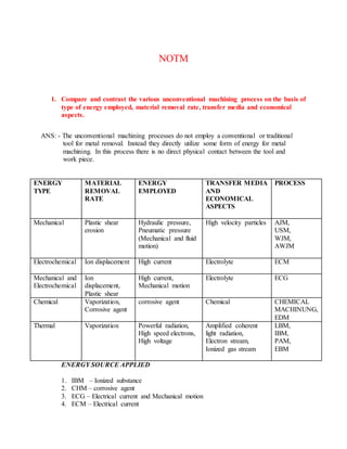
  • 1. NOTM 1. Compare and contrast the various unconventional machining process on the basis of type of energy employed, material removal rate, transfer media and economical aspects. ANS: - The unconventional machining processes do not employ a conventional or traditional tool for metal removal. Instead they directly utilize some form of energy for metal machining. In this process there is no direct physical contact between the tool and work piece. ENERGY TYPE MATERIAL REMOVAL RATE ENERGY EMPLOYED TRANSFER MEDIA AND ECONOMICAL ASPECTS PROCESS Mechanical Plastic shear erosion Hydraulic pressure, Pneumatic pressure (Mechanical and fluid motion) High velocity particles AJM, USM, WJM, AWJM Electrochemical Ion displacement High current Electrolyte ECM Mechanical and Electrochemical Ion displacement, Plastic shear High current, Mechanical motion Electrolyte ECG Chemical Vaporization, Corrosive agent corrosive agent Chemical CHEMICAL MACHINUNG, EDM Thermal Vaporization Powerful radiation, High speed electrons, High voltage Amplified coherent light radiation, Electron stream, Ionized gas stream LBM, IBM, PAM, EBM ENERGY SOURCE APPLIED 1. IBM – Ionized substance 2. CHM – corrosive agent 3. ECG – Electrical current and Mechanical motion 4. ECM – Electrical current
  • 2. 5. EDM – Electrical spark 6. EBM – High-speed electrons 7. AJM – Mechanical and fluid motion 8. LBM – Powerful Radiation. Unconventional machining is classified according to major energy source as follows: Thermal Energy methods: In this method, heat energy is concentrated on a small area of the work piece to melt and vaporize tiny bits of work material. Examples: - i) Laser beam machining ii) Plasma Arc machining iii) Electron beam machining iv) Ion beam machining Electrical energy methods: In this method, electrical energy is directly used to cut the material to get the final shape and size. Examples: i) Electro Discharge machining(EDM) ii) Wire cut EDM Electro chemical energy methods: In this method, material is removed by ion displacement of the work piece material in contact with a chemical solution. Examples: i) Electro chemical machining ii) Electrochemical grinding iii) Electro chemical honing iv) Electro chemical deburring Chemical energy method: This method involves controlled etching of the work piece material in contact with a chemical solution. Example: Chemical machining Mechanical energy methods: In this method, material is removed by mechanical erosion of the work piece material. Example: i) Ultrasonic machining ii) Abrasive jet machining iii) Water jet machining. 2. Explain the USM machine setup and discuss various feed mechanisms. Discuss the influence process parameters and application. ANS: -
  • 3. Ultrasonic machining is a non-traditional machining process. USM is grouped under the mechanical group NTM processes. In ultrasonic machining, a tool of desired shape vibrates at an ultrasonic frequency (19 ~ 25 kHz) with an amplitude of around 15 – 50 μm over the workpiece. Generally, the tool is pressed downward with a feed force, F. Between the tool and workpiece, the machining zone is flooded with hard abrasive particles generally, in the form of a water based slurry. As the tool vibrates over the workpiece, the abrasive particles act as the indenters and indent both the work material and the tool. The abrasive particles, as they indent, the work material, would remove the same, particularly if the work material is brittle, due to crack initiation, propagation and brittle fracture of the material. Hence, USM is mainly used for machining brittle materials {which are poor conductors of electricity and thus cannot be processed by Electrochemical and Electro discharge machining (ECM and EDM)}. FEED MECHANISMS: - 1. Counter weight feed mechanisms 2. Spring loaded feed mechanisms 3. Pneumatic and hydraulic feed mechanisms 4. Electric solenoid control 5. Motor type etc.
  • 4. Process Parameters and their Effects. During discussion and analysis as presented in the previous section, the process parameters which govern the ultrasonic machining process have been identified and the same are listed below along with material parameters • Amplitude of vibration (ao ) – 15 – 50 μm • Frequency of vibration (f) – 19 – 25 kHz • Feed force (F) – related to tool dimensions • Feed pressure (p) • Abrasive size – 15 μm – 150 μm • Abrasive material – Al2 O3 - SiC - B4 C - Boronsilicarbide - Diamond • Flow strength of work material • Flow strength of the tool material
  • 5. • Contact area of the tool – A • Volume concentration of abrasive in water slurry – C MACHINE: - The basic mechanical structure of an USM is very similar to a drill press. However, it has additional features to carry out USM of brittle work material. The workpiece is mounted on a vice, which can be located at the desired position under the tool using a 2 axis table. The table can further be lowered or raised to accommodate work of different thickness. 1. Slurry delivery and return system 2. Feed mechanism to provide a downward feed force on the tool during machining 3. The transducer, which generates the ultrasonic vibration 4. The horn or concentrator, which mechanically amplifies the vibration to the required amplitude of 15 – 50 μm and accommodates the tool at its tip. The ultrasonic vibrations are produced by the transducer. The transducer is driven by suitable signal generator followed by power amplifier. The transducer for USM works on the following principle • Piezoelectric effect • Magnetostrictive effect • Electrostrictive effect Magnetostrictive transducers are most popular and robust amongst all. Typical Magnetostrictive transducer along with horn. The horn or concentrator is a wave-guide, which amplifies and concentrates the vibration to the tool from the transducer.
  • 6. The horn or concentrator can be of different shape like • Tapered or conical • Exponential • Stepped Machining of tapered or stepped horn is much easier as compared to the exponential one. Applications • Used for machining hard and brittle metallic alloys, semiconductors, glass, ceramics, carbides etc. • Used for machining round, square, irregular shaped holes and surface impressions. • Machining, wire drawing, punching or small blanking dies. Limitations • Low MRR • Rather high tool wear • Low depth of hole
  • 7. 3. DEFINE ECM AND ALSO EXPLAINDYNAMIC OF ECM. ANS: - Electro Chemical Machining Electrochemical Machining (ECM) is a non-traditional machining (NTM) process belonging to Electrochemical category. ECM is opposite of electrochemical or galvanic coating or deposition process. Thus ECM can be thought of a controlled anodic dissolution at atomic level of the work piece that is electrically conductive by a shaped tool due to flow of high current at relatively low potential difference through an electrolyte which is quite often water based neutral salt solution. PROCESS: - During ECM, there will be reactions occurring at the electrodes i.e. at the anode or workpiece and at the cathode or the tool along with within the electrolyte. Let us take an example of machining of low carbon steel which is primarily a ferrous alloy mainly containing iron. For electrochemical machining of steel, generally, a neutral salt solution of sodium chloride (NaCl) is taken as the electrolyte. The electrolyte and water undergoes ionic dissociation as shown below as potential difference is applied NaCl ↔ Na+ + Cl- H2O ↔ H+ + (OH)- As the potential difference is applied between the work piece (anode) and the tool (cathode), the positive ions move towards the tool and negative ions move towards the workpiece. Thus the hydrogen ions will take away electrons from the cathode (tool) and
  • 8. from hydrogen gas as: 2H+ + 2e- = H2 ↑ at cathode Similarly, the iron atoms will come out of the anode (work piece) as: Fe = Fe+ + + 2e- Within the electrolyte iron ions would combine with chloride ions to form iron chloride and similarly sodium ions would combine with hydroxyl ions to form sodium hydroxide Na+ + OH- = NaOH In practice FeCl2 and Fe(OH)2 would form and get precipitated in the form of sludge. In this manner it can be noted that the work piece gets gradually machined and gets precipitated as the sludge. Moreover, there is not coating on the tool, only hydrogen gas evolves at the tool or cathode. Depicts the electro-chemical reactions schematically. As the material removal takes place due to atomic level dissociation, the machined surface is of excellent surface finish and stress free. The voltage is required to be applied for the electrochemical reaction to proceed at a steady state. That voltage or potential difference is around 2 to 30 V. The applied potential difference, however, also overcomes the following resistances or potential drops. They are: • The electrode potential • The activation over potential • Ohmic potential drop • Concentration over potential
  • 9. • Ohmic resistance of electrolyte EQUIPMENT The electrochemical machining system has the following modules: • Power supply • Electrolyte filtration and delivery system • Tool feed system • Working tank APPLICATIONS
  • 10. ECM technique removes material by atomic level dissolution of the same by electrochemical action. Thus the material removal rate or machining is not dependent on the mechanical or physical properties of the work material. It only depends on the atomic weight and valiancy of the work material and the condition that it should be electrically conductive. Thus ECM can machine any electrically conductive work material irrespective of their hardness, strength or even thermal properties. Moreover as ECM leads to atomic level dissolution, the surface finish is excellent with almost stress free machined surface and without any thermal damage. ECM is used for • Die sinking • Profiling and contouring • Trepanning • Grinding • Drilling • Micro-machining 4. DEFINE EBM? DISCUSS ABOUT ITS EQUIPMENT SET UP AND PRINCIPLE OF OPERATION. ANS: - ELECTRON BEAM MACHINING – PROCESS Electron beam is generated in an electron beam gun. The construction and working principle of the electron beam gun would be discussed in the next section. Electron beam gun provides high velocity electrons over a very small spot size. Electron Beam Machining is required to be carried out in vacuum. Otherwise the electrons would interact with the air molecules, thus they would lose their energy and cutting ability. Thus the workpiece to be machined is located under the electron beam and is kept under vacuum. The high-energy focused electron beam is made to impinge on the workpiece with a spot size of 10 – 100 μm. The kinetic energy of the high velocity electrons is converted to heat energy as the electrons strike the work material. Due to high power density instant melting and vaporization starts and “melt – vaporization” front gradually progress, Finally the molten material, if any at the top of the front, is expelled from the cutting zone by the high vapor pressure at the lower part. Unlike in Electron Beam Welding, the gun in EBM is used in pulsed mode. Holes can be drilled in thin sheets using a single pulse. For thicker plates, multiple pulses would be required. Electron beam can also be manoeuvred using the electromagnetic deflection coils for drilling holes of any shape.
  • 11. ELECTRON BEAM MACHINING – EQUIPMENT the schematic representation of an electron beam gun, which is the heart of any electron beam machining facility. The basic functions of any electron beam gun are to generate free electrons at the cathode, accelerate them to a sufficiently high velocity and to focus them over a small spot size. Further, the beam needs to be manoeuvred if required by the gun. The cathode as can be seen in Fig. 9.6.3 is generally made of tungsten or tantalum. Such cathode filaments are heated, often inductively, to a temperature of around 2500 0 C. Such heating leads to thermo-ionic emission of electrons, which is further enhanced by maintaining very low vacuum within the chamber of the electron beam gun. Moreover, this cathode cartridge is highly negatively biased so that the thermo-ionic electrons are strongly repelled away from the cathode. This cathode is often in the form of a cartridge so that it can be changed very quickly to reduce down time in case of failure.
  • 12. Just after the cathode, there is an annular bias grid. A high negative bias is applied to this grid so that the electrons generated by this cathode do not diverge and approach the next element, the annular anode, in the form of a beam. The annular anode now attracts the electron beam and gradually gets accelerated. As they leave the anode section, the electrons may achieve a velocity as high as half the velocity of light. ELECTRON BEAM PROCESS – PARAMETERS The process parameters, which directly affect the machining characteristics in Electron Beam Machining, are: • The accelerating voltage • The beam current • Pulse duration • Energy per pulse • Power per pulse • Lens current • Spot size • Power density As has already been mentioned in EBM the gun is operated in pulse mode. This is achieved by appropriately biasing the biased grid located just after the cathode. Switching pulses are given to the bias grid so as to achieve pulse duration of as low as 50 μs to as long as 15 ms. Beam current is directly related to the number of electrons emitted by the cathode or available in the beam. Beam current once again can be as low as 200 μamp to 1 amp.
  • 13. ELECTRON BEAM MACHINING – ADVANTAGES AND LIMITATIONS EBM provides very high drilling rates when small holes with large aspect ratio are to be drilled. Moreover, it can machine almost any material irrespective of their mechanical properties. As it applies no mechanical cutting force, work holding and fixturing cost is very less. Further for the same reason fragile and brittle materials can also be processed. The heat affected zone in EBM is rather less due to shorter pulses. EBM can provide holes of any shape by combining beam deflection using electromagnetic coils and the CNC table with high accuracy. 5. EXPLAIN THE PROCESS OF LBM AND PAM WITH A NEAT SKETCHS. ANS: - Laser Beam Machining – the lasing process Lasing process describes the basic operation of laser, i.e. generation of coherent (both temporal and spatial) beam of light by “light amplification” using “stimulated emission”. In the model of atom, negatively charged electrons rotate around the positively charged nucleus in some specified orbital paths. The geometry and radii of such orbital paths depend on a variety of parameters like number of electrons, presence of neighboring atoms and their electron structure, presence of electromagnetic field etc. Each of the orbital electrons is associated with unique energy levels. At absolute zero temperature an atom is considered to be at ground level, when all the electrons occupy their respective lowest potential energy. The electrons at ground state can be excited to higher state of energy by absorbing energy form external sources like increase in electronic vibration at elevated temperature, through chemical reaction as well as via absorbing energy of the photon. Depicts schematically the absorption of a photon by an electron. The electron moves from a lower energy level to a higher energy level. On reaching the higher energy level, the electron reaches an unstable energy band. And it comes back to its ground state within a very small time by releasing a photon. This is called spontaneous emission. Schematically the same is shown in Fig. 9.6.7 and Fig. 9.6.8. The spontaneously emitted photon would have the same frequency as that of the “exciting” photon. Sometimes such change of energy state puts the electrons in a meta-stable energy band. Instead of coming back to its ground state immediately (within tens of ns) it stays at the elevated energy state for micro to milliseconds. In a material, if more number of electrons can be somehow pumped to the higher meta-stable energy state as compared to number of atoms at ground state, then it is called “population inversion”. Such electrons,
  • 14.
  • 15. at higher energy meta-stable state, can return to the ground state in the form of an avalanche provided stimulated by a photon of suitable frequency or energy. This is called stimulated emission. Fig. 9.6.8 shows one such higher state electron in meta-stable orbit. If it is stimulated by a photon of suitable energy then the electron will come down to the lower energy state and in turn one original photon, another emitted photon by stimulation having some temporal and spatial phase would be available. In this way coherent laser beam can be produced. Fig. 9.6.9 schematically shows working of a laser. There is a gas in a cylindrical glass vessel. This gas is called the lasing medium. One end of the glass is blocked with a 100% reflective mirror and the other end is having a partially reflective mirror. Population inversion can be carried out by exciting the gas atoms or molecules by pumping it with flash lamps. Then stimulated emission would initiate lasing action. Stimulated emission of photons could be in all directions. Most of the stimulated photons, not along the longitudinal direction would be lost and generate waste heat. The photons in the longitudinal direction would form coherent, highly directional, intense laser beam.
  • 16. PLASMA ARC MACHINING (PAM) PLASMA ARC MACHINING (PAM): - Plasma-arc machining (PAM) employs a high-velocity jet of high-temperature gas to melt and displace material in its path called PAM, this is a method of cutting metal with a plasma-arc, or tungsten inert-gas-arc, torch. The torch produces a high velocity jet of high temperature ionized gas called plasma that cuts by melting and removing material from the work piece. Temperatures in the plasma zone range from 20,000° to 50,000° F (11,000° to 28,000° C). It is used as an alternative to ox fuel-gas cutting, employing an electric arc at very high temperatures to melt and vaporize the metal. EQUIPMENT: A plasma arc cutting torch has four components: 1. The electrode carries the negative charge from the power supply. 2. The swirl ring spins the plasma gas to create a swirling flow pattern. 3. The nozzle constricts the gas flow and increases the arc energy density. 4. The shield channels the flow of shielding gas and protects the nozzle from metal spatter.
  • 17. PRINCIPLE OF OPERATION: PAM is a thermal cutting process that uses a constricted jet of high-temperature plasma gas to melt and separate metal. The plasma arc is formed between a negatively charged electrode inside the torch and a positively charged work piece. Heat from the transferred arc rapidly melts the metal, and the high-velocity gas jet expels the molten material from the cut. 6. Estimate the material removal rate in AJM of a brittle material with flow strength of 8 GPa. The abrasive flow rate is 4 gm/min, velocity is 100 m/s and density of the abrasive is 3 gm/cc. ANS: - Flow strength(H) = 8GPa (8*109) Flow rate (ma) = 4 gm/min (4*10-3) Velocity (v) =100 m/s Density of the abrasive (𝜌) = 3gm/cc (3*103) ma*v3/2 MRR=𝜌g 1/4*H3/4 4*10-3/60*(100)3/2 MRR= (3000)1/4*(8*109)3/4 MRR = 18*10-10m3/min 18 mm3/min 7. If in a RC type generator, to get an idle time of 500 μs for open circuit voltage of 100 V and maximum charging voltage of 70 V, determine charging resistance. Assume C = 100 μF. ANS: - Idle time(tc) = 500 μs (5*10-6) Voltage= 100V maximum charging voltage = 70 V C = 100 μF. Tc = - 𝑅𝑐𝐶 𝑰𝒏(1−Vc/Vc) 500*10-6 = - 𝑅𝑐∗200∗10−6 𝑰𝒏(1−70/100 ) Rc = 6𝛺
  • 18. 8. Glass is being machined at a MRR of 6 mm3/min by Al2O3 abrasive grits having a grit diameter of 150 μm. If 100 μm grits were used, what would be the MRR? If from the initial setting the frequency is increased from 20 kHz to 25 kHz. Determine new MRR. (Grit diameter in second case is kept constant) ANS: - MRR = 6mm3/min Grit diameter = 150 μm 100 μm grits = MRR? 𝜎 𝑤(1 + 𝜆) NOW MRR1 = Kdg keeping all other variables unchanged MRR1 MRR2 = dg1 dg2 MRRhang2 = MRR1 dg1 dg2 MRR2 = 6 100 150 = 4mm3/min Now Frequency is increased from 20 kHz to 25 kHz with constant diameter MRR1 = Kf keeping all other variables same MRRNEW = ( F NEW F OLD )3/4 MRROLD = ( 25 20 )3/4 *6 =7.5mm3/min
  • 19. 9. Composition of a Nickel super alloy is as follows: Ni = 70.0%, Cr = 20.0%, Fe = 5.0% and rest Titanium. Calculate rate of dissolution if the area of the tool is 1500 mm2 and a current of 2000 A is being passed through the cell. Assume dissolution to take place at lowest valency of the elements. ANi = 58.71 ρNi = 8.9 νNi = 2 ACr = 51.99 ρCr = 7.19 νCr = 2 AFe = 55.85 ρFe = 7.86 νFe = 2 ATi = 47.9 ρTi = 4.51 νTi = 3 ANS: - Area = 1500mm2 A = dissolution of particle in water as abrasive material 𝜌 = density of material Indentation force for pure iron (F) = 965000coulomb MRR =? NOW 𝜌alloy = 1 ∑ ( 𝑎𝑖 𝜌𝑖 ). = 1 𝑎𝑁𝑖 𝜌𝑁𝑖 + 𝑎𝐶𝑟 𝜌𝐶𝑟 + 𝑎𝐹𝑒 𝜌𝐹𝑒 + 𝑎𝑇𝑖 𝜌𝑇𝑖 = 1 0.7 8.9 + 0.2 7.19 + 0.05 7.86 + 0.05 4.51 = 8.07 gm/cc NOW MRR = 𝑚 𝜌𝑡 = 1 𝐹𝜌 ∑ ( 𝑎𝑖𝑣𝑖 𝐴𝑖 )𝑘 = 1000 96500 ∗8.07∗( 0.75∗2 58.71 + 0 .2∗2 51 .99 + 0.05∗2 55.85 + 0.05∗3 47.9 ) = 0.0356cc/sec =2.14cc/min =2140mm3 /min RATE of dissolution = 𝑀𝑅𝑅 𝐴𝑟𝑒𝑎 = 2140 1500 = 1.43mm3/min
  • 20. 10. In ECM operation of pure iron an equilibrium gap of 2 mm is to be kept. Determine supply voltage, if the total overvoltage is 2.5 V. The resistivity of the electrolyte is 50 Ω- mm and the set feed rate is 0.25 mm/min. ANS: - Equilibrium gap = 2 mm Total overvoltage = 2.5 V Feed rate = 0.25 mm/min Dissolution take place in pure iron = AFe = 55.85 ρFe = 7.86*10-3 νFe = 2 H = 𝑐 𝑓 But C = 𝑉𝐴𝐹𝑒 F𝜌Fer∗vFe C = (𝑉−2.5)∗55.85 96500∗7.8∗10−3∗50∗2 C = (𝑉−2.5) 134 .7 H = (𝑉−2.5) 1347 ∗ 0.25 60 2*5.615 = (𝑉 − 2.5) V = 8.73Volt 11. Determine on time or discharge time if Vo = 100 V and Vd* = 15 V. Spark energy = 0.5 J. Generator is expected for maximum power during charging. Machine resistance = 0.5 Ω. ANS: - Vo = 100 V Vd = 15 V Spark energy = 0.5 J
  • 21. Machine resistance = 0.5 Ω. VC = 0.716VO VC = 0.716*100 VC = 71.6V ES = 1 2 CV2 C = ES 2 V2 C = 2*0.5* 1 71.6∗71.6 C = 195𝜇𝐹 Discharge time Td = 𝑅𝑚∗𝐶 𝐼𝑛 𝑉𝑑 𝑉𝑐 Td = 0.5∗195 𝐼𝑛 15 71.6 Td = 62𝜇𝐹 Name = AMIT SAHNI Program = B. Tech (MAE)