1. CHAPTER 1
INTRODUCTION
1.1 DEFINITIONS
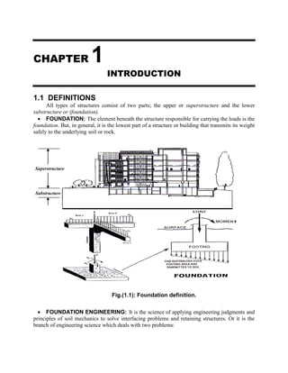
All types of structures consist of two parts; the upper or superstructure and the lower
substructure or (foundation).
FOUNDATION: The element beneath the structure responsible for carrying the loads is the
foundation. But, in general, it is the lowest part of a structure or building that transmits its weight
safely to the underlying soil or rock.
FOUNDATION ENGINEERING: It is the science of applying engineering judgments and
principles of soil mechanics to solve interfacing problems and retaining structures. Or it is the
branch of engineering science which deals with two problems:
Fig.(1.1): Foundation definition.
T
Superstructure
Substructure
2. Foundation Engineering for Civil Engineers Chapter 1: Introduction
2
1. Evaluate the ability of soil to carry a load without shear failure or excessive settlement.
2. To design a proper structural member which can safely transmit the load from
superstructure to soil taking economics into consideration.
1.2 CLASSIFICATION OF FOUNDATIONS
Foundations can be classified basically into two types: shallow and deep.
Shallow Foundations:
These types of foundations are so called because they are placed at a shallow depth
(relative to their dimensions) beneath the soil surface. Their depth may range from the top of soil
surface to about 3 times the breadth (about 6 meters). They include spread footings as circular,
square or rectangular in plans which support columns, and strip footings which support walls and
other similar structures, as well as, combined and mat foundations and soil retaining structures
(retaining walls, sheet piles, excavations and reinforced earth).
Deep Foundations:
The most common of these types of foundations are piles and drilled shafts. They are
called deep because they are embedded very deep (relative to their dimensions) into the soil.
Their depths may run over several tens of meters. They are usually used when the top soil layers
have low bearing capacities (the soil located immediately below the structure is weak or the
applied load from the superstructure is very high, therefore, the load of the structure must be
transmitted to a greater depth).
The shallow foundation shown in Fig.(1.2) has a width B and a length L. The depth of
embedment below the ground surface is equal to Df. This depth must be adequate to avoid:
1. Lateral expulsion of soil beneath the foundation.
2. Seasonal volume changes such as freezing or the zone of active organic materials.
3. Overturning, sliding, rotational failure, and overall soil shear failure and excessive
settlement.
Theoretically, when B/L is equal to zero (that is, L = ), a plane strain case will exist in
the soil mass supporting the foundation. For most practical cases when B/L (1/5 to 1/6), the plane
strain theories will yield fairly good results.
Df
Fig.(1.2): Individual footing.
Ground surface
B
L
Load / meter length
3. Foundation Engineering for Civil Engineers Chapter 1: Introduction
3
Terzaghi (1943) defined a shallow foundation as one in which the depth, fD , is less than or
equal to the width B ( B/Df 1). Otherwise, it is considered as deep foundation.
In some cases, there is a different depth of embedment below the ground surface on both
sides of a foundation as shown in Fig.(1.3). For those cases, fD should be the depth at shallow
side, in addition, the overburden pressure must be compared with soil cohesion to decide the type
of footing required for design as follows:
If ).D.D( 2f1f >
2
qu ………... Design the member as a retaining wall.
If ).D.D( 2f1f
2
qu …………Design the member as a footing.
where, γ is unit weight of soil and uq is unconfined compressive strength of soil.
From soil mechanics principles: )2/45.(tan.c.2)2/45(tan. 2
31
For Unconfined Compressive Strength Test (U.C.S.T.): u1 q and 03 . Therefore:
For pure cohesive soil under undrained condition: ( 0u ): uu c.2q
For c soil: )2/45.(tan.c.2qu
P
G.S.
2fD
1fD
B
Fig.(1.3): Depth of embedment.
G.S.
)(
)(
03 u1 q
c
tan.cS
2
b - c soil
)(
)(
03 u1 q
0,...
2
q
cS u
u
u
uc
a - Pure cohesive soil
Fig.(1.4): Unconfined compressive strength test.
4. Foundation Engineering for Civil Engineers Chapter 1: Introduction
4
1.3 SETTLEMENT AT ULTIMATE LOAD
Settlement means a vertical displacement of a structure or footing or road,…etc.. The
settlement of the foundation at ultimate load, uS , is quite variable and depends on several factors.
Based on laboratory and field test results, the approximate ranges for uS values of soils are given
below:
Soil B/Df B/Su (%)
Sand 0 5 to 12
Sand Large 25 to 28
Clay 0 4 to 8
Clay Large 15 to 20
For any foundation, one must ensure that the load per unit area of foundation does not
exceed a limiting value, thereby causing shear failure in soil. This limiting value is the ultimate
bearing capacity, .ultq and generally by using a factor of safety of 3 to 4 the allowable bearing
capacity, .allq can be calculated as:
S.F
q
q .ult
.all …….………………………….…..……….………………..(1.1)
However, based on limiting settlement conditions, there are other factors which must be taken
into account in deriving the allowable bearing capacity. The total settlement, TS , of a foundation
will be the sum of three components:
1. Elastic or immediate settlement, iS ; (major in sand),
2. Primary and secondary consolidation settlements, cS and csS ; (major in clay).
TS = iS + cS + csS …..…………………………..……………………..(1.2)
Most building codes provide an allowable settlement limit for a foundation which may be
well below the settlement derived corresponding to .allq given by Eq.(1.1). Thus, the bearing
capacity corresponding to the allowable settlement must also be taken into consideration. A given
structure with several shallow foundations may undergo two types of settlement:
1. Uniform or equal total settlement, and 2. Differential settlement.
Fig.(1.5a) shows a uniform settlement which occurs when a structure is built over rigid
structural mat. However, depending on the load of various foundation components, a structure
may experience differential settlement. A foundation may also undergo uniform tilt (Fig.(1.5b))
or non-uniform settlement (Fig.(1.5c)). In these cases, the angular distortion, , can be defined
as:
L
SS (min)t(max)t
(for uniform tilt) …….....…………………..(1.3)
1
(min)t(max)t
L
SS
(for non-uniform settlement) …….………..(1.4)
Limits for allowable differential settlement of various structures are available in building
codes. Thus, the final decision on the allowable bearing capacity of a foundation depends on:
(a) the ultimate bearing capacity, (b) the allowable settlement, and (c) the allowable
differential settlement for the structure.
5. Foundation Engineering for Civil Engineers Chapter 1: Introduction
5
Problem (1.1):
A 30 cm x 30 cm column is loaded with 40 Ton. Check whether the column can be placed
on soil directly or not if the allowable bearing capacity of soil is:
(a) .allq = 50 kg/cm2
, and
(b) .allq = 1.0 kg/cm2
.
Solution:
(a)
A
Q
q .all
or 800
50
40000
A cm2
(minimum required area) < 900 cm2
(area of column)……… O.K.
or 4.44
30x30
40000
q .all kg/cm2
< 50 kg/cm2
…… O.K.
No failure may happen; and the column can be placed directly on the soil.
(b) 40000
0.1
40000
A cm2
(minimum required area) > 900 cm2
(area of column) ..... N.O.K.
(Not safe) and the column in this case can not be placed directly on soil, therefore, an
enlarged base is required.
A = 40000 cm2
= 4 m2
, assuming square area: AB = √4 = 2m. (see Fig.(1.6)).
Fig.(1.5): Settlement of a structure.
(a) Uniform settlement (b) Uniform tilt (c) Non-uniform settlement
L G.S. L G.S.
2L
G.S.
.)(mintS
.)(maxtS
.)(mintS
.)(maxtS
1L
St St
Fig.(1.6): Solution of problem (1.1).
40 Ton
2m
2m
(b) 2
cm/kg.0.1.qall
40 Ton
(a) 2
cm/kg.50.qall
30 cm x 30 cm
6. Foundation Engineering for Civil Engineers Chapter 1: Introduction
6
1.4 TYPES OF FAILURE IN FOOTINGS
It is possible due to load that a footing fails by one or two of the following:
(1) Shear failure: This failure must be checked against:-
(i) Punching shear, and (ii) Wide beam shear. No shear failure is satisfied by providing an
adequate thickness of concrete (see Fig.(1.7)).
(2) Tension failure: This failure decides the locations and positions of steel distribution. No
tension failure is satisfied by providing an adequate steel reinforcement (see Fig. (1.7)).
1.5 TYPES OF FOUNDATIONS
1.5.1 SHALLOW FOUNDATIONS
(1) Spread, Isolated or Individual Column Footing:
It is a footing of plain or reinforced concrete that supports a single column. It may be either a
square, circular or rectangular in shape, or cross sectional area (see Fig.(1.8)). However, the
design of square or circular spread footings is simpler than that of rectangular one. This is evident
due to the twice calculation required for rectangular footing compared with other ones. The
rectangular footing is preferred in case of a moment, since the length is increased in the direction
of moment to make the resultant of loads within the middle third of footing.
d
d
Square footing Rectangular footingCircular footing
A4
BB
B B
L
Fig.(1.8): Spread footing.
(i) Punching shear at (d/2) from face of column.
d/2
L
d/2
d/2
d/2
L
(c) Internal column:
)LL(2bo
d/2
L
d/2
L
(b) Corner column:
LLbo
d/2
L
d/2
d/2
L
(a) External column:
LL2bo
Edgeoffooting
Edgeoffooting
Edge of footing
(ii) Wide beam shear at (d) from face of column.
d
.ultq
uM uM
(iii) Bending moment.
Centerline
Fig.(1.7): Types of failure in footing.
7. Foundation Engineering for Civil Engineers Chapter 1: Introduction
7
(2) Combined Footing (reinforced concrete only):
It is a footing that connects several columns and can take one of the following shapes:
Rectangular Combined Footing (see Fig.(1.9)):
(a) Used along the walls of building at property lines where the footing for a wall column
can not extend outside the limits of the structure.
(b) If the loads from several columns are transmitted to the same footing, the footing should
be proportioned so that its centroid coincides with the center of gravity of the column
loads.
Trapezoidal Combined Footing (see Fig.(1.10)):
(a) If the maximum load exists at the exterior column,
(b) It is not possible to make the resultant of loads passes through the centroid of the footing.
(i.e., If
2
L
> x >
3
L
).
Strap or Cantilever Combined Footing (see Fig.(1.11)):
(a) If there is an eccentricity, and/ or
(b) If ( x <
3
L
).
Col. 1 Col. 2
800 kN
0.5m
0.5m
1200 kN
4.0m 1.3m
0.3m x 0.3m 0.4m x 0.4m
Property line
Soil pressure
Fig.(1.9): Rectangular combined footing.
a
x
Pu2
Pu1
b
c. g.
x
S
Propertyline
L
Resultant
Col. 2: 0.4 m x 0.4 m
DL= 385 kN
LL= 270 kN
Col. 1: 0.4 m x 0.4 m
DL= 190 kN
LL= 300 kN
strapd
footingd
e = 0.65m
0.15 m
5.5 m
Resultant
Fig.(1.10): Trapezoidal combined footing. Fig.(1.11): Strap combined footing.
8. Foundation Engineering for Civil Engineers Chapter 1: Introduction
8
(3) Wall or Strip Footing (see Fig.(1.12)):
This footing represents a plain strain condition, such as a footing beneath a wall. In this case,
the footing area is calculated as:
.allq
length..unit/load..Total
1.x.BArea
(4) Raft Foundation (see Fig.(1.13)):
It is a combined footing that covers the entire area beneath a structure and supports all the
walls and columns, such that: applied
f
q
I
c.M
A
Q
< .allq
It is used when:
All spread footings areas represent greater than 50 % of the entire site area,
There are a basement and ground water table problems,
The bearing capacity of soil is very low, and the building loads are so heavy, and
A large differential settlement is expected to occur.
Sand
Q = 200 kN/m
0.75m
m = 18 kN/m3
=10%, Gs = 2.65
1.5m
Q / meter length
fD
B
Wall footing Wall footingW.T.
Fig.(1.12): Wall footing.
c = 0 , 30
F
8 m8 m
0.25 m0.25 m
H E J D
A
4.25 m
CG B I
4.25 m
y
x
8 m
0.25 m
0.25 m
7 m
7 m
7 m
400 kN 500 kN 450 kN
1500 kN 1500 kN 1200 kN
1500 kN 1500 kN 1200 kN
400 kN 500 kN 350 kN
Fig.(1.13): Raft foundation.
9. Foundation Engineering for Civil Engineers Chapter 1: Introduction
9
1.5.2 DEEP FOUNDATIONS
(1) Pile Foundation (see Fig.(1.14)):
Pile is a structural member made of wood, steel or concrete used to transmit the load from
superstructure to underlying soil stratum in the following cases:
When the soil profile consists of weak compressible soils.
If .allapplied q....q .
To resist tension or uplift forces induced by horizontal forces acting on superstructure
due to wind or earthquakes loads.
Piles usually are of two types:
(a) Driven piles, suitable for granular soils.
(b) Bored piles, suitable for clayey soils.
Each type of these piles can be made of precast concrete or cast in place.
(2) Pier Foundation (see Fig.(1.15)):
It is an underground structural member that serves the same purpose as a footing. However,
the ratio of the depth of foundation to the base width of piers is usually greater than 4 (Df /B >4),
whereas, for footings, this ratio is commonly less than unity (Df /B 1). A drilled pier is a
cylindrical column that has essentially the same function as piles. The drilled pier foundation is
used to transfer the structural load from the upper unstable soils to the lower firm stratum.
G.S.
Hard stratum
Total load, Q
(a) Single Pile
Skin friction, Qs
End bearing, Qb
Pile Cap
m Piles
G.S.
n Piles
S
b
a
S
Total load
(b) Layout of Piles in groups.
L
Fig.(1.14): Single and group piles.
10. Foundation Engineering for Civil Engineers Chapter 1: Introduction
10
A part of the pier above the
foundation is known as a pier shaft. The
base of a pier shaft may rest directly on a
firm stratum or it may be supported on
piles. A pier shaft located at the end of a
bridge and subjected to lateral earth
pressure is known as an abutment.
Essentially, piers and piles serve the
same purpose. The distinction is based on
the method of installation. A pile is
installed by driving and a pier by auger
drilling. In general, a single pier is used to
support the same heavy column load
resisted by group of piles.
(3) Floating Foundation:
If the weight of the constructed structure or building is equal to the weight of the replaced
excavated soil, a foundation is known as fully compensated foundation. But if this condition is
not satisfied, it is considered as semi-compensated foundation.
(4) Caissons:
A hollow shaft or box with sharp ends or cutting edges for ease penetrating into soil used to
isolate the site of project from the surrounding area. The material inside the caisson is removed
by dredging through openings in the top or by hand excavation. Whereas, the lower part of it may
be sealed from atmosphere and filled with air under pressure to exclude water from work space
(see Fig.(1.16)).
Fig.(1.15): Pier foundations.
Fig.(1.16): Methods of caisson construction.
(a) The Chicago method. (b) The Gow method.
11. Foundation Engineering for Civil Engineers Chapter 1: Introduction
11
1.5.3 RETAINING STRUCTURES
(1) Retaining Walls:
Retaining walls are structures used to provide stability for earth or other materials at their
natural slopes. In general, they are used to support soil banks and water or also to maintain
difference in the elevation of the ground surface on each of wall sides. Retaining walls are
commonly supported by soil (or rock) underlying the base slab, or supported on piles; as in case
of bridge abutments and where water may undercut the base soil as in water front structures.
There are many types of retaining walls, each type serves different purposes and fit
different requirements. They are mainly classified according to its behavior against the soil as:
(a) Gravity Retaining Walls are constructed of plain concrete or stone masonry. They depend
mostly on their own weight and any soil resting on the wall for stability. This type of
construction is not economical for walls higher than 3m (see Fig.(1.17a)).
(b) Semi-Gravity Retaining Walls are modification of gravity wall in which small amounts of
reinforcing steel are introduced. This helps minimizing the wall section (see Fig.(1.17b)).
(c) Cantilever Retaining Walls are the most common type of retaining walls that used for wall
height up to 8m. It derives its name from the fact that its individual parts behave as, and are
designed as, cantilever beams. The stability of this type is a function of the strength of its
individual parts (see Fig.(1.17c)).
(d) Counterfort Retaining Walls are similar to cantilever retaining walls, at regular intervals,
however, they have thin vertical concrete slabs behind the wall known as counterforts that tie
the wall with the base slab together and reduce the shear and bending moment. These walls
are economical when the wall height exceeds 8m (see Fig.(1.17d)).
(e) Buttress Retaining Walls are similar to counterfort retaining walls, except for the bracings
which are in front of the walls and are in compression instead of tension.
(f) Bridge Abutments are special type of retaining walls, not only containing the approach fill,
but serving as a support for the bridge superstructure (see Fig.(1.17e)).
(g) Crib Walls are built-up members of pieces of precast concrete, metal, or timber and are
supported by anchor pieces embedded in the soil for stability (see Fig.(1.17f)).
Among these walls, only the cantilever retaining walls and bridge abutments are much used.
12. Foundation Engineering for Civil Engineers Chapter 1: Introduction
12
(2) Sheet Piles Walls:
These are classified as: anchored and cantilevered sheet pile walls; each kind may be used in
single or double sheet walls.
(a) Cantilever or Free Sheet - Pile Walls are constructed by driving a sheet pile to a depth
sufficient to develop a cantilever beam type reaction to resist the active pressures on the wall.
(b) Semi-gravity wall
(e) Bridge abutment (f) Crib walls
Fig.(1.17): Common types of retaining walls.
(c) Cantilever wall (d) Counterfort wall
(a) Gravity walls
13. Foundation Engineering for Civil Engineers Chapter 1: Introduction
13
That is, the embedment length which must be adequate to resist both lateral forces as well as
bending moments (see Fig.(1.18a)).
(b) Anchored or Fixed Sheet - Pile Walls are types of retaining walls found in waterfront
construction, which are used to form wharves or piers for loading and unloading ships (see
Fig.(1.18b)).
(3) Cofferdams:
(a) Single and Double Sheet Pile Cofferdams: They are used for depth of water not
exceeding 3.0 m.
(b) Cellular Cofferdams: They are used for higher depths of water, i.e., greater than 3.0 m.
These are relatively watertight enclosures of wood or steel sheet piles. Before the
cofferdam is pumped out, one set of bracing is installed just above the water line. The water level
is then lowered to the elevation at which another set of bracing must be installed. Successive
lowering of water level and installation of bracing continue until the cofferdam is pumped out
(see Fig.(1.19)).
Fig.(1.19): Cellular cofferdams.
(a) Circular, economical for deep cells.
(b) Diaphragm, economical in quiet water. (c) Modified circular.
45
45
30 30
(b) Anchored sheet pile wall.
Dredge line
sq
C
H
D
A
B
Anchor tie rod
(a) Cantilever sheet pile wall.
C
B
A
H
D
Dredge line
Point of rotation
Fig.(1.18): Types of sheet piling walls.
14. Foundation Engineering for Civil Engineers Chapter 1: Introduction
14
REFERENCES
Das, Braja M (2010),” Principles of Geotechnical Engineering”, 7th
edition, Library of Congress
Control Number: 2009930622, ISBN-13: 978-0-495-41130-7, ISBN-10: 0-495-41130-2
Meyerhof, G. G., (1965),“Shallow foundations”, J. Soil Mech. Found. Div., ASCE, Vol.91(2),
No.21.
Peck, R., Hanson, W. and Thornburn, T.H. (1974),”Foundation engineering”, John Wiley &
Sons, New York.
Terzaghi, K., Peck, R. and Mesri, G. (1996),”Soil mechanics in engineering practice”, John
Wiley-Interscience Publication, John Wiley & Sons, New York.
Vesic, A. S., (1973), “Analysis of ultimate loads of shallow foundations”. J. Soil Mech. Found.
Div., ASCE, Vol.99(1), No.45.