
Recommended
More Related Content
What's hot
What's hot (20)
Similar to Bourdon sensing pressure gauge.
Similar to Bourdon sensing pressure gauge. (20)
Recently uploaded
Recently uploaded (20)
Bourdon sensing pressure gauge.
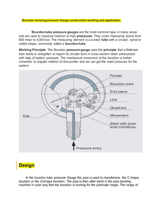
- 1. Bourdon sensing pressure Gauge construction working and application. Bourdon tube pressure gauges are the most common type in many areas and are used to measure medium to high pressures. They cover measuring spans from 600 mbar to 4,000 bar. The measuring element is a curved tube with a circular, spiral or coiled shape, commonly called a bourdon tube. Working Principle: The Bourdon pressure gauge uses the principle that a flattened tube tends to straighten or regain its circular form in cross-section when pressurized with help of system pressure. The mechanical movement of the bourdon is further converted to angular rotation of dial pointer and we can get the exact pressure for the system. Design In the bourdon tube pressure Gauge the pipe is used to manufacture the C shape bourdon or the Coil type bourdon. The pipe is then after bend in the pipe bending machine in such way that the bourdon is coming for the particular range. The range of
- 2. the bourdon is depending on the size of the pipe. The one end of the bourdon is sealed with the filler wire and the other rend is connected the socket. When the pressurized liquids, gas or air is come into contact with the bourdon the bourdon change its size or shape. The direction of this movement is determined by the curvature of the tubing, with the inside radius being slightly shorter than the outside radius. A specific amount of pressure causes the "C" shape to open up, or stretch, a specific distance. When the pressure is removed, the spring nature of the tube material returns the tube to its original shape and the tip to its original position relative to the socket. Manufacturing process of bourdon tube. 1. The bourdon is made up of the hollow seamless pipe with all the annealing and othe process. The gauge builder specifies the desired wall thickness, material, configuration, and diameter 2. The most of the common method to manufacture the bourdon sensing pressure gauge is the rolling process of the bourdon. The tube is then roll into the C shape. The "C" shape of the tube is generally formed in an automatic rolling machine or the manual rolling machine. The bourdon making is done simultaneously by rolling and curving the bourdon at the same Time. One roller grasps the tubing end and forms the inside radius, while the other provides outside pressure to maintain uniform contact with the tubing. Each roller contains a groove that fits around the outside of the tubing; these grooves allow the tubing to maintain its circular shape rather than being flattened. 3. The same roller that grabs and bends the tubing also contains a saw blade. As the roller continues turning after creating the bend, the saw blade on it cuts the tubing to the proper length. The tubing is then heat treated in ovens. Other components 1. Socket: The socket is basically a block of metal that serves as a connector to the source of the pressure medium; a mount for the case, dial, and movement; and as an attachment slot for the Bourdon tube. The one end of the socket is threaded and the other end is open. The socket may be cast, forged, extruded, or machined from bar stock. Most sockets are made on automated machining centers that turn, drill, mill, and thread all in one cycle. 2. Movements: The movement is the gear mechanism used to convert the the motion and provide the smooth working facility. The geared mechanisms that contain a pinion (a rotating shaft), sector, support plates, hairspring, and spacer columns. The mechanism converts the somewhat linear displacement of the Bourdon tip into rotary movement, as well as providing a means for calibration adjustment. The pointer is fastened to the rotating shaft, or pinion. 6. The case,
- 3. dial, and pointer may be sheet metal stampings, plastic moldings, or castings. Stampings and moldings require little further processing, but castings will require some machining—trimming off excess material, for instance—to meet the final requirements. Final assembly The bourdon tube is welded to the socket. its closed end is attached to the socket by soldering, brazing, or welding. The free end of the Bourdon tube is precisely located during this assembly operation, and then sealed, usually by the same means used to join the tube to the socket. Once the Bourdon tube and socket assembly is secure, the tip of the unsupported end of the "C" is attached to an End link. This End link The bourdon tube is not move by 360 span so the movement used the gear mechanical advantage to convert the motion into 360. The other components the movement, pointer, and dial are then assembled onto the socket as a group. Calibration 1. Calibration occurs just before the final assembly of the gauge to the protective case and Dial. The assembly consisting of the socket, tube, and movement is connected to a pressure source with a known "master" gauge. A "master" gauge is simply a high accuracy gauge of known calibration. Adjustments are made in the assembly until the new gauge reflects the same pressure readings as the master. Accuracy requirements of 2 percent difference are common, but some may be 1 percent, .5 percent, or even .25 percent. Selection of the accuracy range is solely dependant upon how important the information desired is in relationship to the control and safety of the process. Most manufacturers use a graduated dial featuring a 270 degree sweep from zero to full range. These dials can be from less than I inch (2.5 centimeters) to 3 feet (.9 meter) in diameter, with the largest typically used for extreme accuracy. By increasing the dial diameter, the circumference around the graduation line is made longer, allowing for many finely divided markings. These large gauges are usually very fragile and used for master purposes only. Masters themselves are inspected for accuracy periodically using dead weight testers, a very accurate hydraulic apparatus that is traceable to the National Bureau of Standards in the United States.
- 4. Application. 1. Oil and gas. 2. Refinery. 3. Sea water application 4. Cement industry. 5. Building management system. 6. Chemical plant. 7. Water purification plant.