Download to read offline


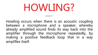
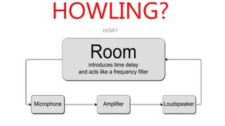
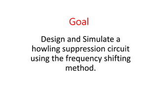
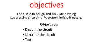
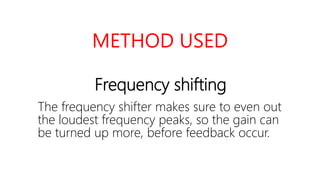
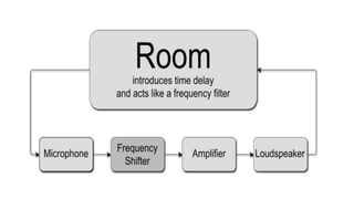
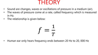
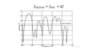

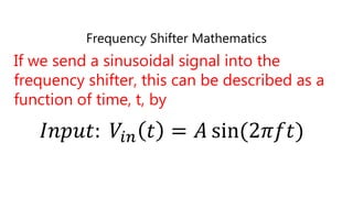
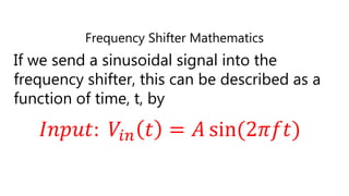
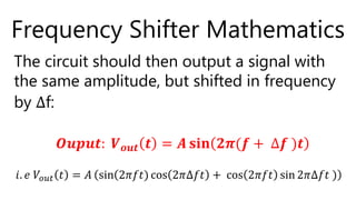

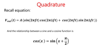
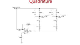


The document discusses the design and simulation of a howling suppression circuit for public address systems, focusing on acoustic coupling and positive feedback loops that lead to howling. It explores frequency shifting as a technique to suppress howling by equalizing frequency peaks and includes a mathematical framework for the frequency shifter and additional circuit components. Objectives include designing, simulating, and testing the suppression system to prevent feedback before it occurs.