

Recommended
More Related Content
What's hot
What's hot (20)
Similar to Induction motors
Similar to Induction motors (20)
More from Dr.Raja Masood Larik
More from Dr.Raja Masood Larik (20)
Recently uploaded
Recently uploaded (20)
Induction motors
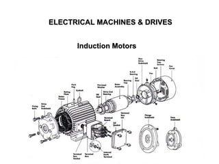
- 1. ELECTRICAL MACHINES & DRIVES Induction Motors
- 2. 2 THREE-PHASE INDUCTION MOTOR • The stator of a 3-phase induction motor carries a 3-phase winding (stator winding) while the rotor carries a short-circuited winding (rotor winding). • The rotor winding derives its voltage and power from the externally energized stator winding through electromagnetic induction. Advantages • Simple and rugged construction requiring little maintenance • Lower cost • High efficiency and good power factor • Self starting torque Disadvantages • It is essentially a constant speed motor and its speed cannot be changed easily • Its starting torque is inferior to d.c. shunt motor. Lecture Notes by Dr.R.M.Larik
- 3. 3 CONSTRUCTION Stator • It consists of a steel frame which encloses a hollow, cylindrical core made up of thin laminations of silicon steel to reduce hysteresis and eddy current losses. • A number of evenly spaced slots are provided on the inner periphery of the laminations. • The coils of insulated enamel wires are interconnected to form a balanced 3-phase star or delta circuit. • When 3-phase supply is given to the stator winding, a rotating magnetic field of constant magnitude is produced. • This rotating field induces currents in the rotor by electromagnetic induction. Lecture Notes by Dr.R.M.Larik
- 4. 4 CONSTRUCTION (Contd.) Rotor The rotor, mounted on a shaft, is a hollow laminated core having slots on its outer periphery. Squirrel Cage Rotor • Copper or aluminum bars are placed in the slots. • All the bars are joined at each end by metal rings called end rings forming a permanently short- circuited winding • It is not possible to add any external resistance to the rotor circuit to have a large starting torque. Lecture Notes by Dr.R.M.Larik
- 5. 5 CONSTRUCTION (Contd.) Rotor (Contd.) Wound Rotor • It consists of a laminated cylindrical core having a 3-phase winding uniformly distributed in the slots and is star-connected • The open ends of the rotor winding are brought out and joined to three insulated slip rings mounted on the rotor shaft • The carbon brushes resting on the slip rings are connected to a 3-phase star- connected rheostat Lecture Notes by Dr.R.M.Larik
- 6. 6 CONSTRUCTION (Contd.) Rotor (Contd.) Wound Rotor (Contd.) • At starting, the external resistances are included in the rotor circuit to give high starting torque. • The external resistances are used during starting period only. • When the motor attains normal speed, the three brushes are short-circuited Lecture Notes by Dr.R.M.Larik
- 7. 7 ROTATING MAGNETIC FIELD • When a 3-phase winding is energized from a 3-phase supply, a rotating magnetic field is produced such that its poles do not remain in a fixed position on the stator but go on shifting their positions around the stator. • To see how rotating field is produced, consider a 2-pole, 3-phase winding. • The three phases Ph-1, Ph-2 and Ph-3 are energized from a 3-phase source and currents in these phases are indicated as II, III and IIII • The fluxes produced by these currents are given by: ϕx = ϕm sin ωt ϕy = ϕm sin (ωt – 120o) ϕz = ϕm sin (ωt – 240o) Lecture Notes by Dr.R.M.Larik
- 8. 8 ROTATING MAGNETIC FIELD (Contd.) Lecture Notes by Dr.R.M.Larik
- 9. 9 PRINCIPLE OF OPERATION • When 3-phase stator winding is energized from a 3-phase supply, a rotating magnetic field is set up which rotates round the stator at synchronous speed Ns (= 120 f/P). • The rotating field passes through the air gap and cuts the rotor conductors. • Due to the relative speed between the rotating flux and the stationary rotor, e.m.f.s are induced in the rotor conductors and currents start flowing in the rotor conductors. Lecture Notes by Dr.R.M.Larik
- 10. 10 PRINCIPLE OF OPERATION (Contd.) • Since the current-carrying rotor conductors are lying in the magnetic field produced by the stator mechanical force acts on the rotor conductors. • The sum of the mechanical forces on all the rotor conductors produces a torque which tends to move the rotor in the same direction as the rotating field • The fact that rotor is urged to follow the stator field can be explained by Lenz’s law which states that the direction of rotor currents will be such that they tend to oppose the cause producing them. • The cause producing the rotor currents is the relative speed between the rotating field and the stationary rotor conductors. • Hence to reduce this relative speed, the rotor starts running in the same direction as that of stator field and tries to catch it. Lecture Notes by Dr.R.M.Larik
- 11. 11 SLIP SPEED • The rotor can never reach the speed of stator flux, otherwise, there would be no relative speed between the stator field and rotor conductors, no induced rotor currents and, and no torque • Due to friction and windage losses the rotor slows down, hence, the rotor speed (N) is always less than the stator field speed (Ns). • The difference between the synchronous speed Ns of the rotating stator field and the actual rotor speed N is called slip and expressed as: % age slip, s = Ns− N Ns x 100 • When the rotor is stationary (i.e., N = 0), slip, s = 1 or 100 %. • In an induction motor, the change in slip from no-load to full-load is 0.1% to 3% so it is essentially a constant-speed motor. Lecture Notes by Dr.R.M.Larik
- 12. 12 ROTOR CURRENT FREQUENCY • Frequency of a voltage or current induced due to the relative speed between a winding and a magnetic field is given by: Frequency = NP 120 where N = Relative speed between magnetic field and the winding P = Number of poles • For a rotor speed N, the relative speed between the rotating flux and the rotor is Ns - N. • Rotor current frequency f' is given by; f’ = (Ns− N) P 120 = s Ns P 120 = s f Lecture Notes by Dr.R.M.Larik
- 13. 13 ROTOR CURRENT FREQUENCY (Contd.) • When the rotor is at standstill or stationary (i.e., s = 1), the frequency of rotor current is the same as that of supply frequency f' = s f = 1 x f = f • As the rotor picks up speed, the relative speed between the rotating flux and the rotor decreases. Consequently, the slip s and hence rotor current frequency decreases. Problem 1(a): A 3-phase induction motor is wound for 4 poles and is supplied from 50-Hz system. Calculate a) the synchronous speed b) rotor speed, when slip is 4% and c) rotor frequency when rotor runs at 600 rpm. Lecture Notes by Dr.R.M.Larik
- 14. 14 NUMERICAL PROBLEMS (Contd.) Solution: Pole = 4, f = 50 Hz Ns ?, Rotor speed N ? (when slip s = 0.04), Rotor frequency f’ ? (when rotor speed N = 600 r.p.m.) Ns = 120 f P = 120 x 50 4 = 1500 r.p.m. N = Ns (1 – s) = 1500 (1 – 0.04) = 1440 r.p.m. Problem 1(a) Lecture Notes by Dr.R.M.Larik
- 15. 15 NUMERICAL PROBLEMS (Contd.) Problem 1(b) A 50 Hz 4-pole, 3-phase induction motor has a current of frequency 2 Hz. Determine (i) the slip and (ii) speed of motor. When N = 600 r.p.m. Slip s = Ns− N Ns = 1500 − 600 1500 = 0.6 Rotor frequency f’ = s f = 0.6 x 50 = 30 Hz Problem 1(a) Solution (Contd.): Lecture Notes by Dr.R.M.Larik
- 16. 16 NUMERICAL PROBLEMS (Contd.) Solution: P = 4, N = 1440 rpm, f = 50 Hz Ns = 120 𝑓 𝑃 = 120 𝑥 50 4 = 1500 rpm Problem 1(c) A 4 pole three phase star connected stator induction motor running at 1440 rpm at full load. The supply frequency from main is 50 hertz. Calculate: a) Percent slip of the motor b) Rotor frequency when running at 1000 rpm c) Stator revolving magnetic field speed in rpm Lecture Notes by Dr.R.M.Larik
- 17. 17 NUMERICAL PROBLEMS (Contd.) % Slip s at 1440 rpm = Ns− N Ns x 100 = 1500 − 1440 1500 x 100 = 4 % % Slip s at 1000 rpm = Ns− N Ns x 100 = 1500 − 1000 1500 x 100 = 33.3 % Rotor frequency at 1000 rpm fr = s f = 0.333 x 50 = 16.65 Hz Stator revolving magnetic field speed in rpm Ns = 1500 rpm Problem 1(c) Solution (Contd.): Lecture Notes by Dr.R.M.Larik
- 18. 18 EFFECT OF SLIP ON THE ROTOR CIRCUIT • When the rotor is stationary (s = 1), hence, the per phase rotor e.m.f. E2 has a frequency equal to that of supply frequency f. • The e.m.f. E2 induced in the rotor at standstill is maximum as the relative speed between the rotor and the revolving stator flux is maximum. • Thus, for a slip s, the rotor induced e.m.f. will be Er = sE2 • The frequency of the induced e.m.f. will likewise become fr = sf2 • Due to decrease in frequency of the rotor e.m.f., the rotor reactance will also decrease. i.e. Xr = sX2 where X2 and f2 are rotor reactance and frequency under standstill and Xr and Er rotor reactance and e.m.f. under running conditions. Lecture Notes by Dr.R.M.Larik
- 19. 19 NUMERICAL PROBLEMS Problem 2(a) A 3-phase induction motor having a star-connected rotor has an induced e.m.f. of 80 volts between slip-rings at standstill on open- circuit. The rotor has a resistance and reactance per phase of 1 and 4 respectively. Calculate current/ phase and power factor when (a) slip-rings are short-circuited (b) slip-rings are connected to a star- connected rheostat of 3 per phase. Solution: Induced e.m.f. E2 (open circuit standstill) between slip rings = 80 V, Rotor resistance / ph R2 = 1 , Rotor reactance / phase X2 = 4 Rotor current / ph ? Cos Φ2 ? when a) slip-ring short circuited, b) slip- ring connected to star connected rheostat of 3 / ph a) Standstill rotor e.m.f / ph E2 = 80 3 = 46.2 V Lecture Notes by Dr.R.M.Larik
- 20. 20 NUMERICAL PROBLEMS (Contd.) Rotor impedance/ ph Z2 = R2 2 + X2 2 = 1 2 + 4 2 = 4.12 Rotor current / ph = E2 Z2 = 46.2 4.12 = 11.2 A Rotor power factor Cos Φ2 = R2 Z2 = 1 4.12 = 0.243 b) Rotor resistance (with additional resistance) / ph = 3 + 1 = 4 Rotor impedance / ph Z2 ′ = R2 2 + X2 2 = 4 2 + 4 2 = 5.66 Rotor current / ph = E2 Z2 ′ = 46.2 5.66 = 8.16 A Rotor power factor Cos Φ2 = R2 Z2 ′ = 4 5.66 = 0.707 Problem 2(a) Solution (Contd.): Lecture Notes by Dr.R.M.Larik
- 21. 21 NUMERICAL PROBLEMS (Contd.) Problem 2(b): A 3-phase slip ring motor gives a reading of 55 V across slip rings on open circuit when at standstill with normal voltage applied. The rotor is star connected and has impedance of (0.7 + j5) per phase. Find the rotor current and p.f. when the machine is (i) at standstill with slip ring joined to a star-connected starter with a phase impedance of (4 + j3) ohms and ii) when running normally with a 5% slip. Lecture Notes by Dr.R.M.Larik
- 22. 22 RELATION BETWEEN TORQUE AND ROTOR POWER FACTOR • Similar to d.c. motor, in induction motor the torque is proportional to the product of flux per stator pole and the rotor current. • Taking the power factor of the rotor into account: T Ф I2 cos Ф2 or T = k Ф I2 cos Ф2 where I2 = rotor current at standstill, Ф2 = angle between rotor e.m.f. and rotor current, k = a constant • Denoting rotor e.m.f. at standstill by E2, we have that E2 Ф T E2 I2 cos Ф2 or T = k1 E2 I2 cos Ф2 , where k1 is another constant. Lecture Notes by Dr.R.M.Larik
- 23. 23 STARTING TORQUE Let E2 = rotor e.m.f. / phase at standstill; R2 = rotor resistance/ phase; X2 = rotor reactance/ phase at standstill Z2 = R2 2 + X2 2 = rotor impedance / phase at standstill Then, I2 = E2 Z2 = E2 R2 2+ X2 2 ; cos Ф2 = R2 Z2 = R2 R2 2+ X2 2 Standstill starting torque Tst = k1 E2 cos Ф2 or Tst = k1 E2 E2 R2 2+ X2 2 x R2 R2 2+ X2 2 = k1E2 2R2 R2 2+ X2 2 Lecture Notes by Dr.R.M.Larik
- 24. 24 STARTING TORQUE OF 3-PHASE INDUCTION MOTORS • The rotor circuit of an induction motor has low resistance and high inductance. • At starting, the rotor frequency is equal to the stator frequency (i.e., 50 Hz) so that rotor reactance is large compared with rotor resistance and rotor current lags the rotor e.m.f. by a large angle, the power factor is low and consequently the starting torque is small. • When resistance is added to the rotor circuit, the rotor power factor is improved which results in improved starting torque. • Since the rotor bars are permanently short-circuited, it is not possible to add any external resistance in the rotor circuit at starting, hence, the starting torque of such motors is low. • Squirrel cage motors have starting torque of 1.5 to 2 times the full-load value with starting current of 5 to 9 times the full-load current. Squirrel-cage Motors Lecture Notes by Dr.R.M.Larik
- 25. 25 STARTING TORQUE OF 3-PHASE INDUCTION MOTORS • The resistance of the rotor circuit of such motors can be increased through the addition of external resistance. • By inserting the proper value of external resistance (so that resistance = inductance), maximum starting torque can be obtained. • As the motor accelerates, the external resistance is gradually cut out until the rotor circuit is short-circuited on itself for running conditions. Wound Rotor Motors Lecture Notes by Dr.R.M.Larik
- 26. 26 TORQUE/SPEED CURVE OF INDUCTION MOTORS • The torque developed by a conventional 3-phase motor depends on speed. • In the diagram, T represents the nominal full-load torque of the motor. • The starting torque (at N = 0) is 1.5 T and the maximum torque (also called breakdown torque) is 2.5 T. • As long as the two torques are in balance, the motor will run at constant (but lower) speed. However, if the load torque exceeds 2.5 T, the motor will suddenly stop. • At full-load, the motor runs at a speed of N. • When mechanical load increases, motor speed decreases till the motor torque again becomes equal to the load torque. Lecture Notes by Dr.R.M.Larik
- 27. 27 SPEED REGULATION OF INDUCTION MOTORS Speed regulation of an induction motor is given by: % age speed regulation = No − NFL NFL x 100 where N0 = no-load speed of the motor NF.L. = full-load speed of the motor If the no-load speed of the motor is 800 r.p.m. and its fall-load speed in 780 r.p.m., then change in speed is 800 - 780 = 20 r.p.m. and percentage speed regulation = 20 x 100/780 = 2.56%. Lecture Notes by Dr.R.M.Larik
- 28. 28 SPEED CONTROL OF 3-PHASE INDUCTION MOTORS N = (1 – s) Ns = (1 – s) 120 𝑓 𝑃 Speed N of an induction motor can be varied by changing supply frequency number of poles or slip. Squirrel Cage Motors • The speed of motor is changed by changing the number of stator poles but only two or four speeds are possible by this method. • Two-speed motor has one stator winding that may be switched through suitable control equipment to provide two speeds, one of which is half of the other. Wound Rotor Motors Speed can be changed by varying the stator line voltage, varying the rotor resistance or inserting and varying a foreign voltage in the rotor circuit Lecture Notes by Dr.R.M.Larik
- 29. 29 POWER FACTOR OF INDUCTION MOTORS Wound Rotor Motors Power factor of an induction motor is given by; Power factor, cos Φ = Active component of current (I cos Φ) Total current (I) The air-gap between the stator and rotor greatly increases the reluctance of the magnetic circuit, hence, an induction motor draws a large magnetizing current (Im) i) At no load, an induction motor draws a large magnetizing current and a small active component to meet the no-load losses, hence, the motor takes a high no-load current lagging the applied voltage by a large angle (about 0.1 lagging) ii) When an induction motor is loaded, the active component of current increases while the magnetizing component remains constant, hence, the power factor is increased. Lecture Notes by Dr.R.M.Larik
- 30. 30 POWER LOSSES IN AN INDUCTION MOTOR Fixed Losses i) Stator iron loss ii) Friction and windage loss Variable Losses i) Stator copper loss ii) Rotor copper loss The rotor iron loss is negligible because the frequency of rotor currents under normal running condition is small. Electric power fed to the stator of an induction motor suffers losses and finally converted into mechanical power. Lecture Notes by Dr.R.M.Larik
- 31. 31 STARTING OF 3-PHASE INDUCTION MOTORS Starting Squirrel-Cage Motors Except direct-on-line starting, all other methods of starting squirrel-cage motors employ reduced voltage across motor terminals at starting. Direct - on - line Starting • The motor is started by connecting it directly to 3-phase supply. • The impedance of the motor at standstill is relatively low and when it is directly connected to the supply system, the starting current will be high (4 to 10 times the full-load current) and power factor will be low. • The starting torque is comparatively low. • If this large starting current flows for a long time, it may overheat the motor and damage the insulation. Lecture Notes by Dr.R.M.Larik
- 32. 32 STARTING OF 3-PHASE INDUCTION MOTORS (Contd.) Stator Resistance Starting • External resistances are connected in series with each phase of stator winding during starting • This causes voltage drop across the resistances so that voltage available across motor terminals is reduced and hence the starting current.Lecture Notes by Dr.R.M.Larik
- 33. 33 STARTING OF 3-PHASE INDUCTION MOTORS (Contd.) Stator Resistance Starting (Contd.) • When the motor attains rated speed, the resistances are completely cut out and full line voltage is applied to the rotor. • This method suffers from two drawbacks. i) The reduced voltage applied to the motor during the starting period lowers the starting torque and hence increases the accelerating time. ii) A lot of power is wasted in the starting resistances. Lecture Notes by Dr.R.M.Larik
- 34. 34 STARTING OF 3-PHASE INDUCTION MOTORS (Contd.) Autotransformer Starting • The induction motor is connected to a reduced supply (65 – 80%)at starting and then connected to the full voltage as the motor picks up sufficient speed. • Autotransformer starting has the advantages of low power loss, low starting current and less radiated heat. Lecture Notes by Dr.R.M.Larik
- 35. 35 STARTING OF 3-PHASE INDUCTION MOTORS (Contd.) Star-delta Starting • Stator winding of motor is designed for delta operation and is connected in star during starting period. • When the machine is up to speed, connections are changed to delta. Lecture Notes by Dr.R.M.Larik
- 36. 36 STARTING OF 3-PHASE INDUCTION MOTORS (Contd.) Star-delta Starting (Contd.) • The six leads of the stator windings are connected to the changeover switch. • At the instant of starting, the changeover switch is thrown to “Start” position which connects the stator windings in star. • Each stator phase gets V/ 3 volts (V is the line voltage) resulting in reduction of the starting current. • When the motor picks up speed, the changeover switch is thrown to “Run” position which connects the stator windings in delta. • Now each stator phase gets full line voltage V. Disadvantage At starting, stator phase voltage is 1/ 3 times the line voltage, hence, torque is (1/ 3)2 or 1/3 times the value it would have with delta - connection. Lecture Notes by Dr.R.M.Larik
- 37. 37 STARTING OF 3-PHASE INDUCTION MOTORS (Contd.) Starting of Slip-Ring Motors • Slip-ring motors are invariably started by rotor resistance starting. • A variable star-connected rheostat is connected in the rotor circuit through slip rings and full voltage is applied to the stator winding Lecture Notes by Dr.R.M.Larik
- 38. 38 SLIP-RING MOTORS VERSUS SQUIRREL CAGE MOTORS Advantages of slip-ring induction motors over squirrel cage motors: • High starting torque with low starting current. • Smooth acceleration under heavy loads. • No abnormal heating during starting. • Good running characteristics after external rotor resistances are cut out • Adjustable speed. Disadvantages of slip-ring motors are: • The initial and maintenance costs are greater • The speed regulation is poor when run with resistance in the rotor circuit Lecture Notes by Dr.R.M.Larik