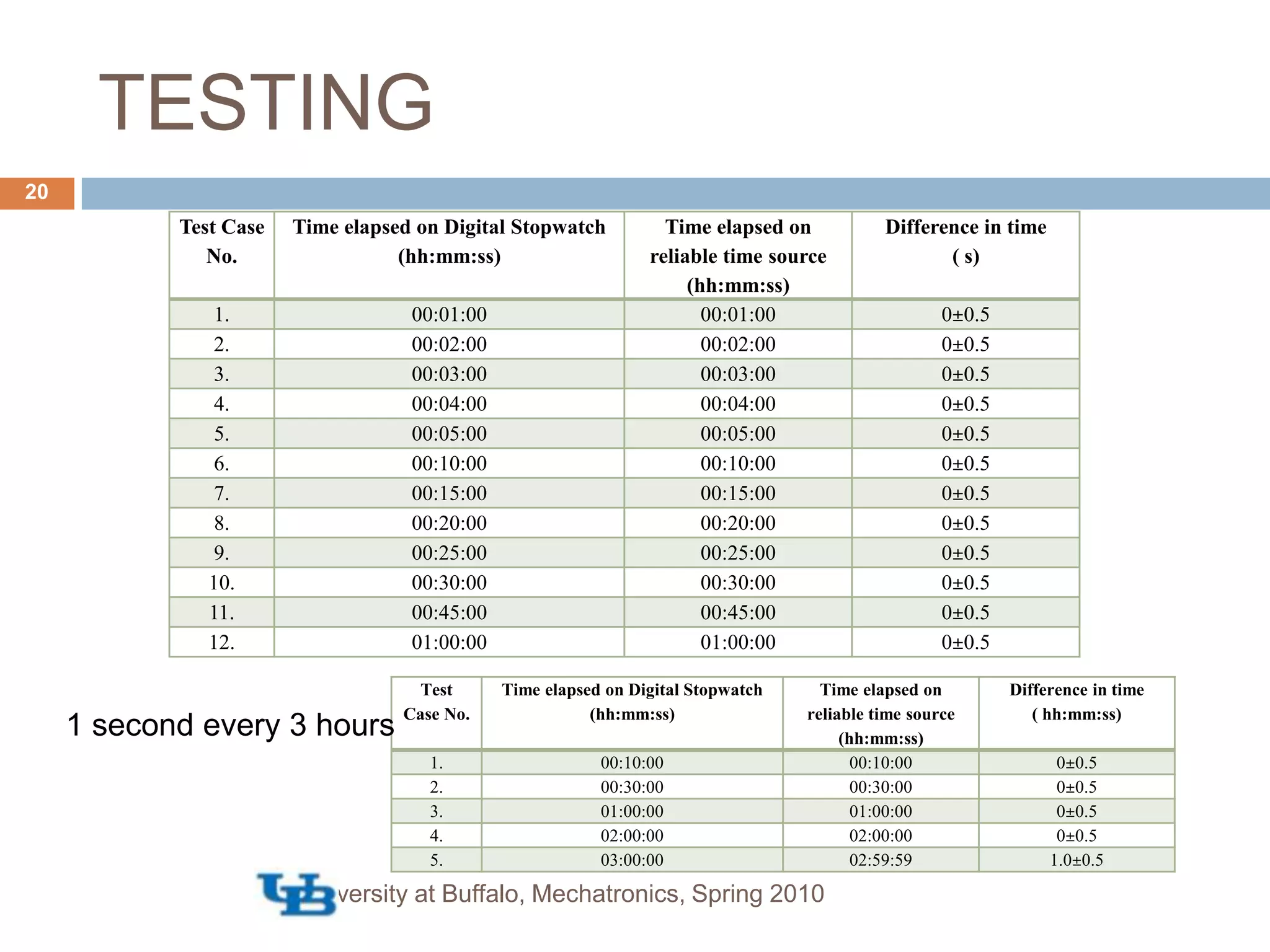
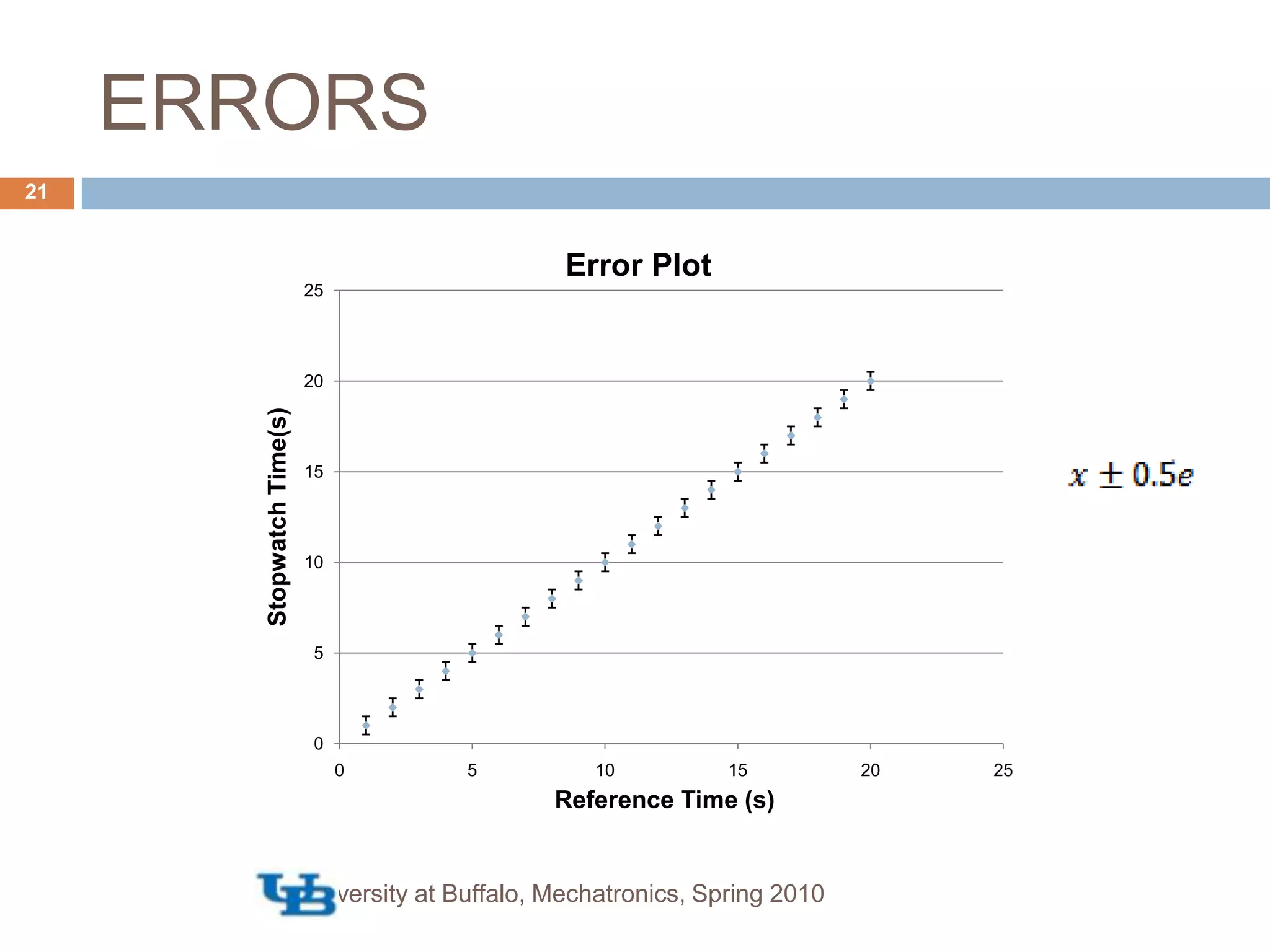
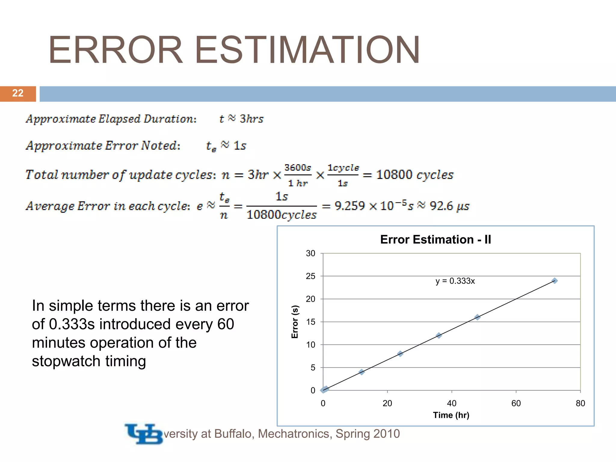
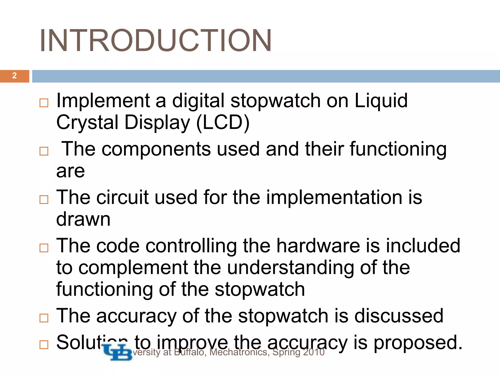
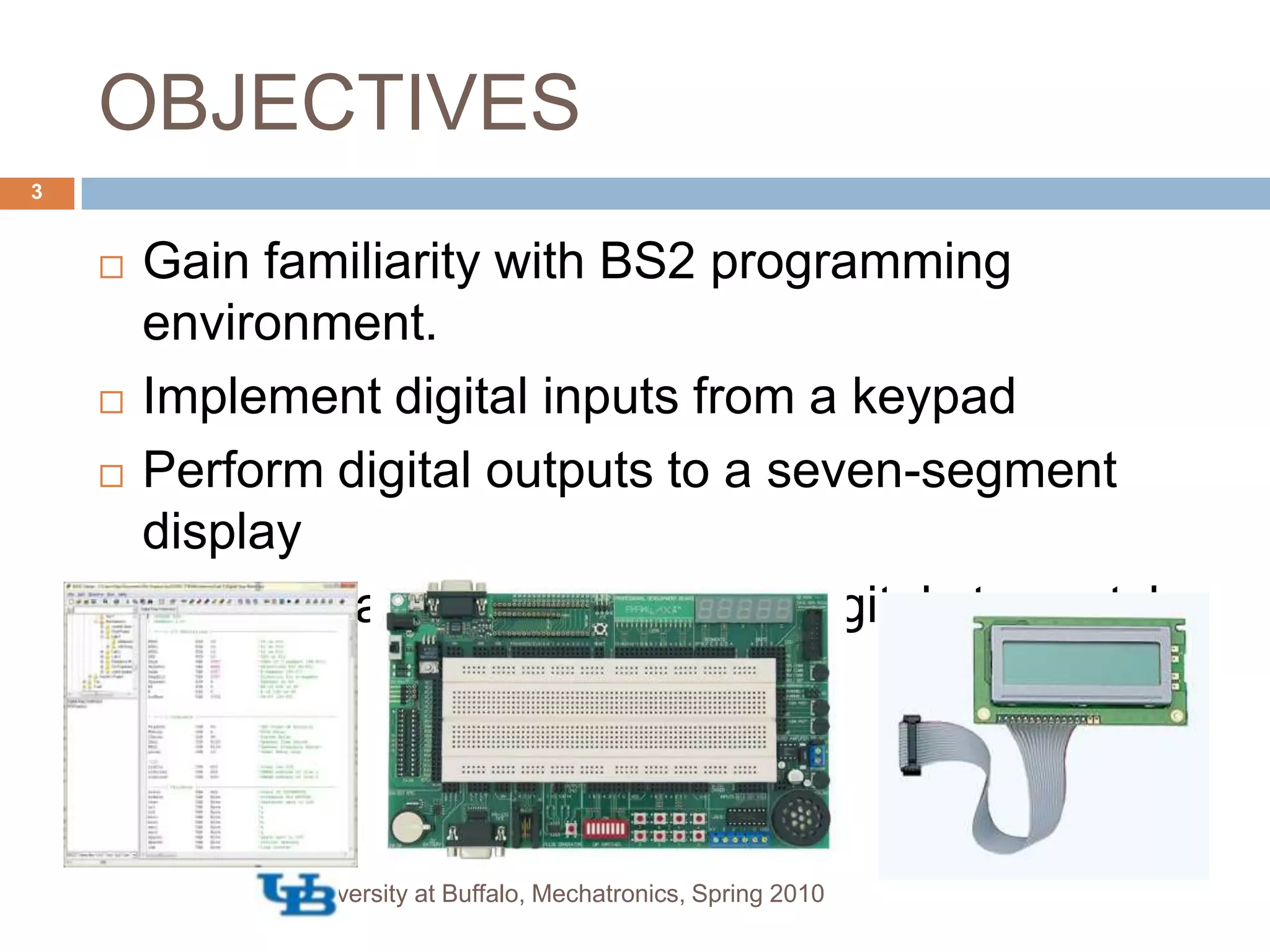
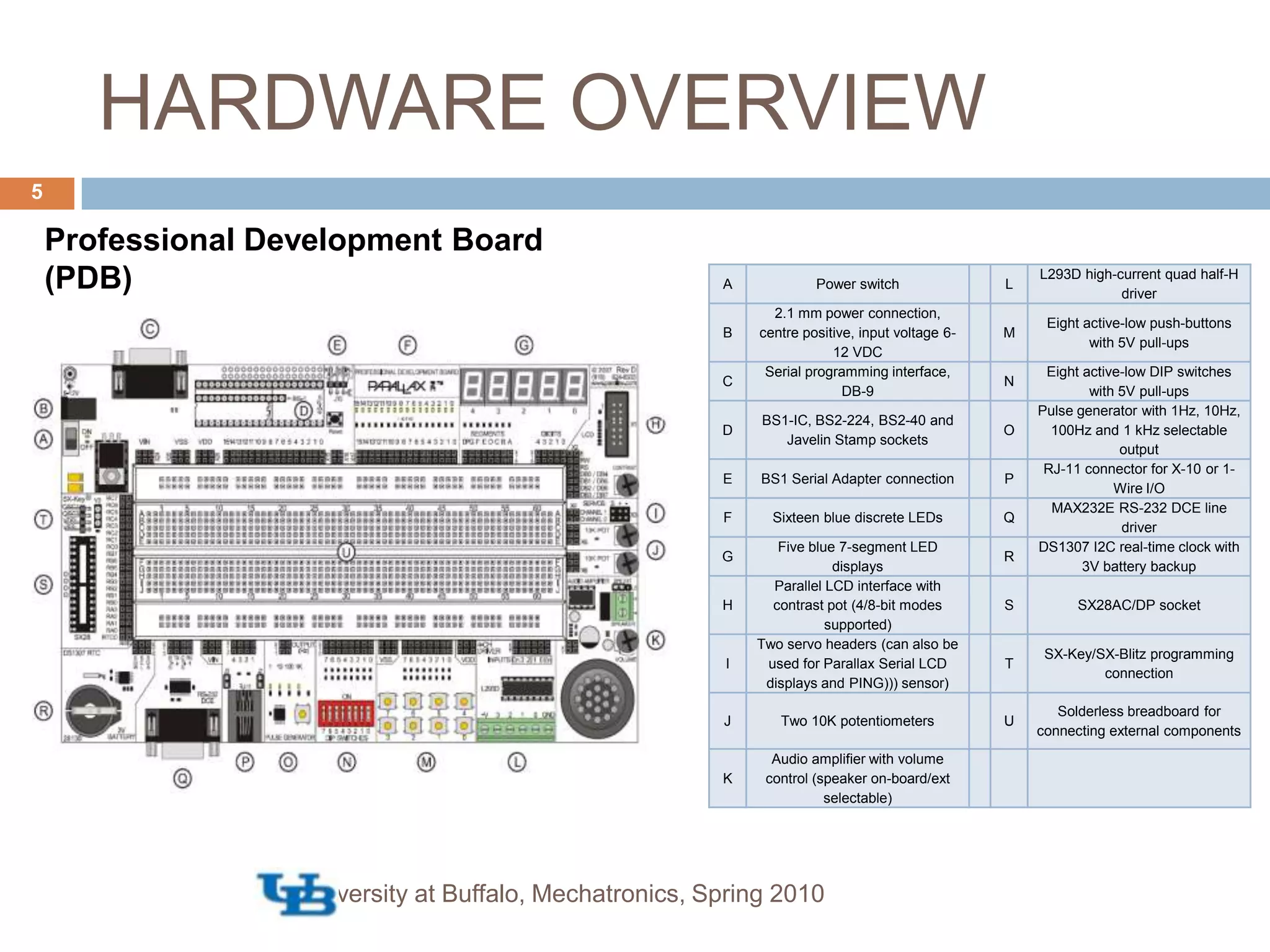
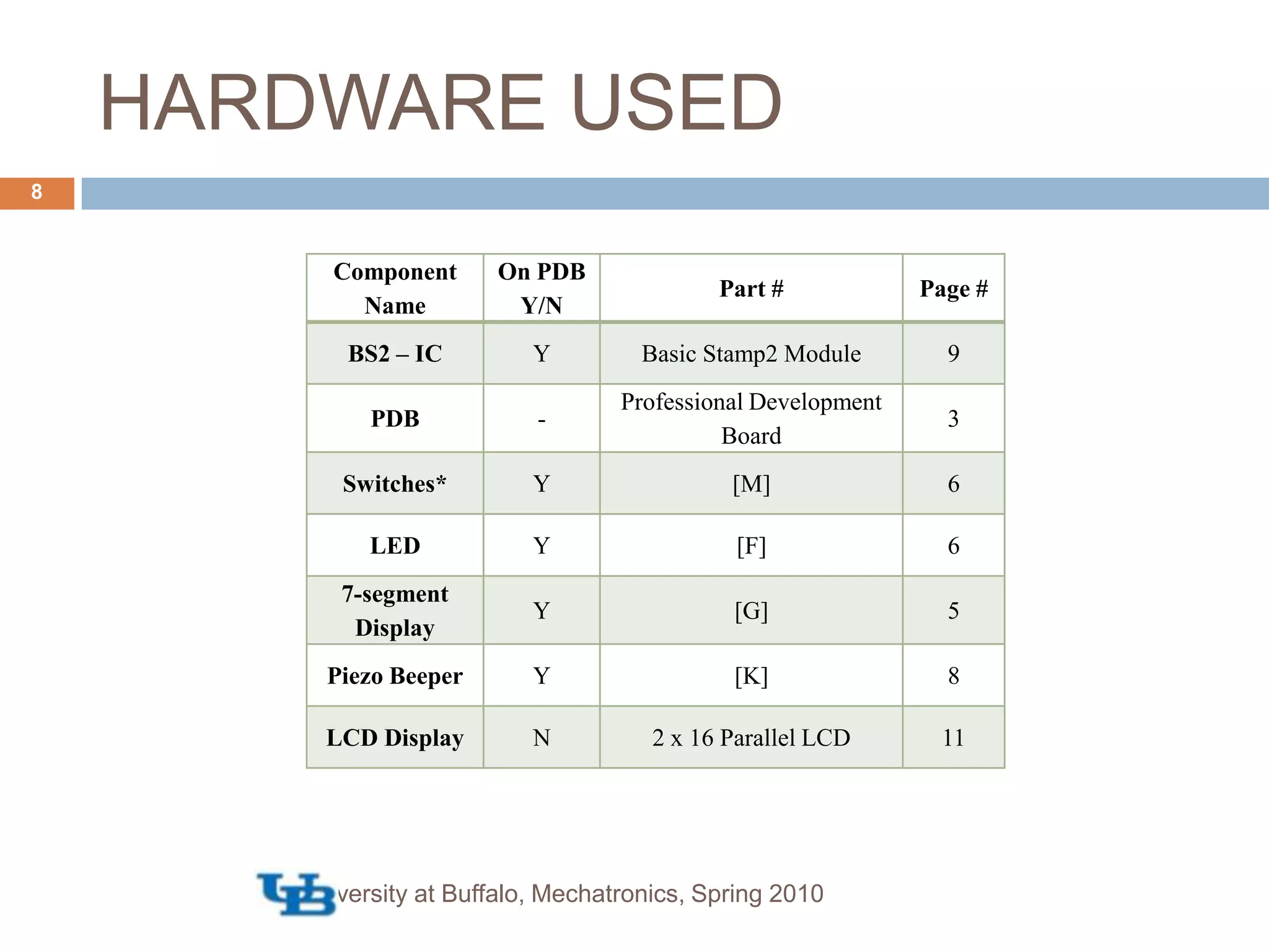
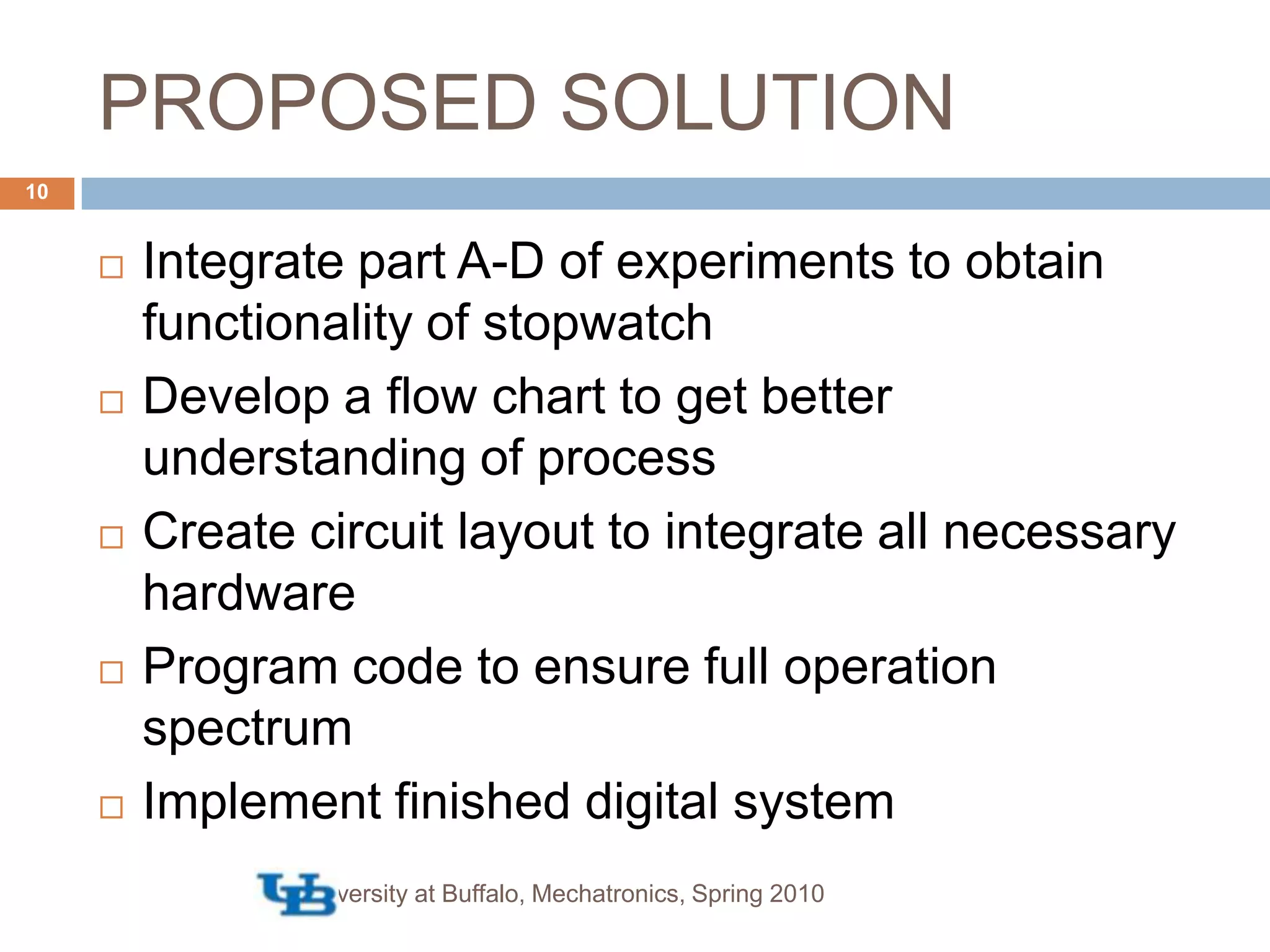
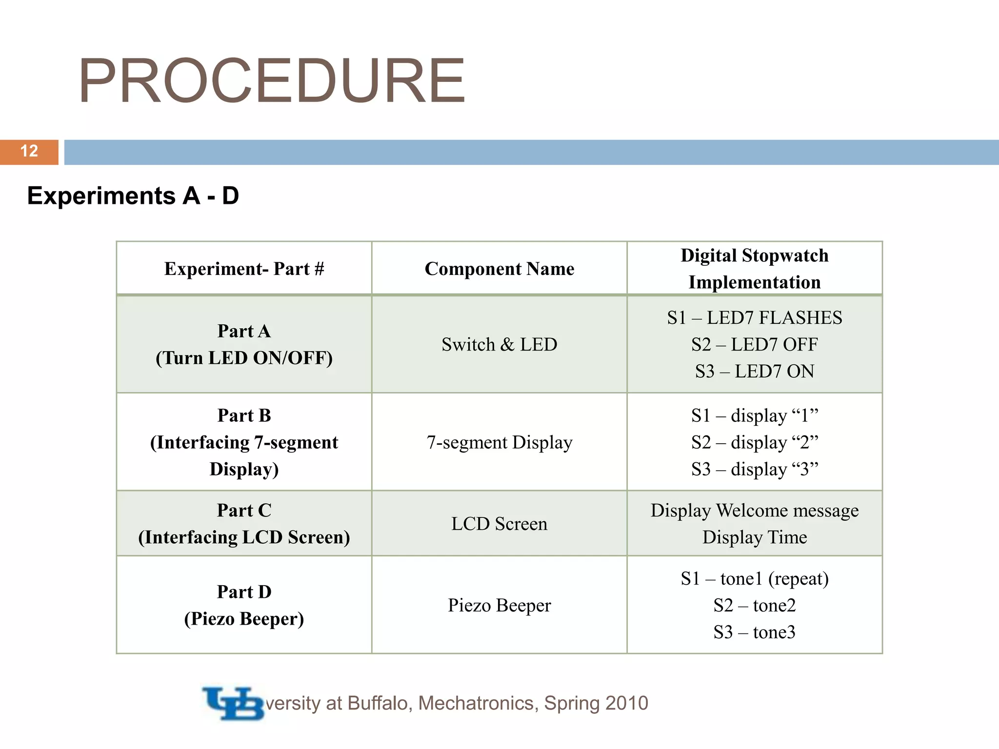
This document describes implementing a digital stopwatch using a Basic Stamp II microcontroller. The objectives are to gain familiarity with the BS2 programming environment, interface a LCD display as a digital stopwatch, and implement digital inputs from a keypad and outputs to a display. The hardware used includes a Basic Stamp II module, development board, and LCD. The procedure involves experiments, a flow chart, circuit design, and programming the stopwatch functionality. Testing achieves a timing accuracy of within 0.5 seconds over 3 hours of operation.
![IMPLEMENTING A DIGITAL STOPWATCH USING BASIC STAMP IIMAE 576 [MECHATRONICS] LAB-1University at Buffalo, Mechatronics, Spring 2010Chembrammel Elavunkal SrinivasanVishwajeetGROUP E](https://image.slidesharecdn.com/wiki-lab1-100513094640-phpapp01/75/Implementing-a-Digital-Stopwatch-Using-Basic-Stamp2-1-2048.jpg)
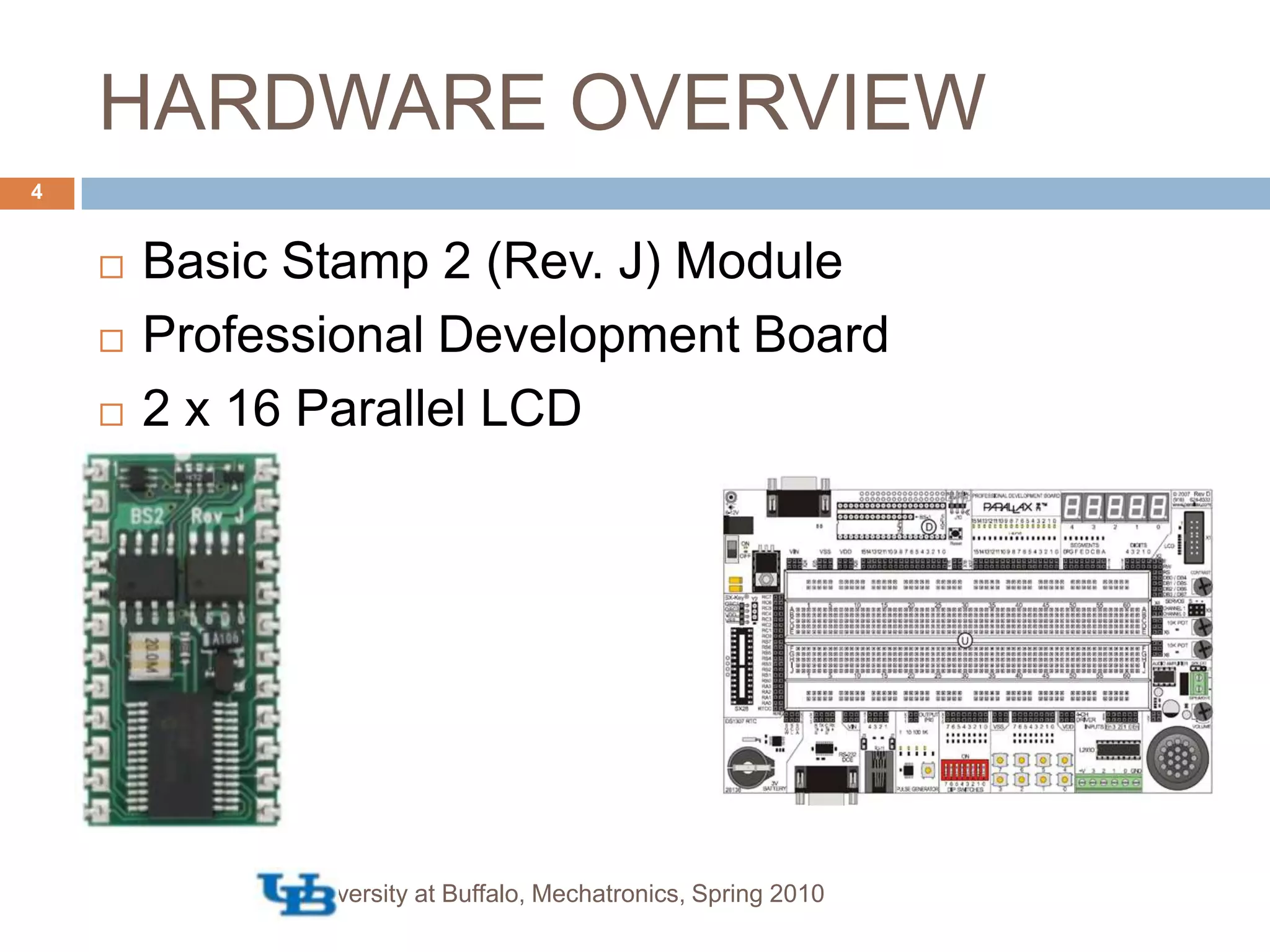
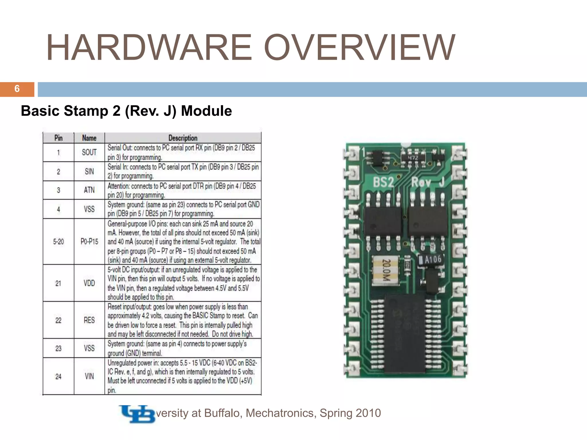
![HARDWARE OVERVIEW7[i] http://www.parallax.com/tabid/134/List/1/ProductID/1/Default.aspxBasic Stamp 2 (Rev. J) ModuleEEPROMRegulatorInterpreterPIC16F57University at Buffalo, Mechatronics, Spring 2010](https://image.slidesharecdn.com/wiki-lab1-100513094640-phpapp01/75/Implementing-a-Digital-Stopwatch-Using-Basic-Stamp2-7-2048.jpg)
![CONSTRAINTS [Self Imposed]University at Buffalo, Mechatronics, Spring 201011Ensure clean hardware implementationReduce use of hardware resourcesStreamline coding to achieve optimal functionalityTest and achieve maximum timer accuracyAdditional GoalsWelcome Message](https://image.slidesharecdn.com/wiki-lab1-100513094640-phpapp01/75/Implementing-a-Digital-Stopwatch-Using-Basic-Stamp2-11-2048.jpg)
![PROCEDURE [Flow Chart]Flow ChartUniversity at Buffalo, Mechatronics, Spring 201013](https://image.slidesharecdn.com/wiki-lab1-100513094640-phpapp01/75/Implementing-a-Digital-Stopwatch-Using-Basic-Stamp2-13-2048.jpg)
![PROCEDURE [Circuit]CircuitUniversity at Buffalo, Mechatronics, Spring 201014](https://image.slidesharecdn.com/wiki-lab1-100513094640-phpapp01/75/Implementing-a-Digital-Stopwatch-Using-Basic-Stamp2-14-2048.jpg)
![PROCEDURE [Pin Layout]Pin LayoutUniversity at Buffalo, Mechatronics, Spring 201015](https://image.slidesharecdn.com/wiki-lab1-100513094640-phpapp01/75/Implementing-a-Digital-Stopwatch-Using-Basic-Stamp2-15-2048.jpg)
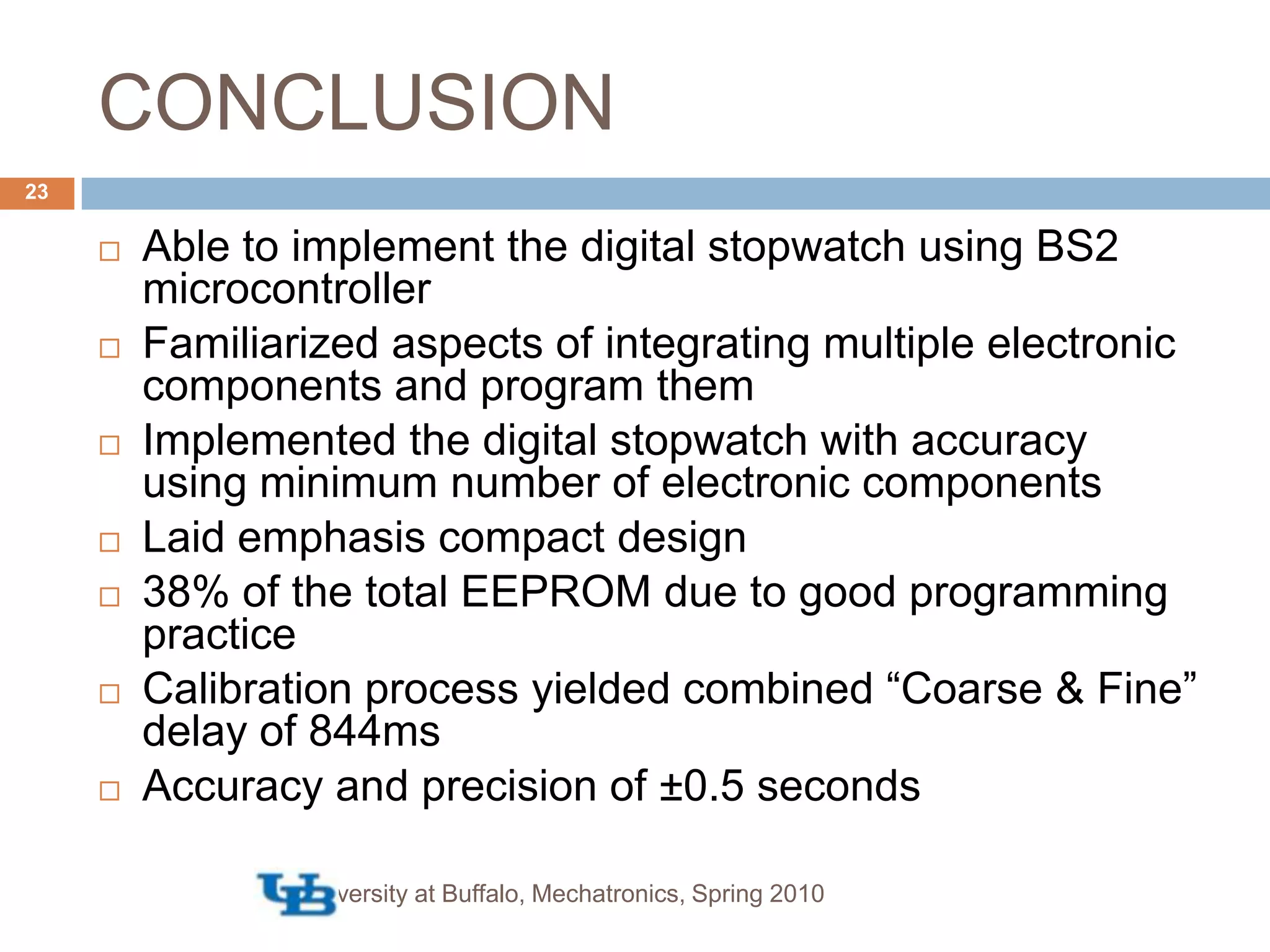
![PROCEDURE [Source Code]University at Buffalo, Mechatronics, Spring 201016Source Code (Attached to Webpage) USED: 38% of the EEPROM 5 registers Please note the source code to run the digital stopwatch is attached to this website for your convenience](https://image.slidesharecdn.com/wiki-lab1-100513094640-phpapp01/75/Implementing-a-Digital-Stopwatch-Using-Basic-Stamp2-16-2048.jpg)
![PROCEDURE [Special Connections]*These connections should always be ensured for proper operation of the systemUniversity at Buffalo, Mechatronics, Spring 201017](https://image.slidesharecdn.com/wiki-lab1-100513094640-phpapp01/75/Implementing-a-Digital-Stopwatch-Using-Basic-Stamp2-17-2048.jpg)