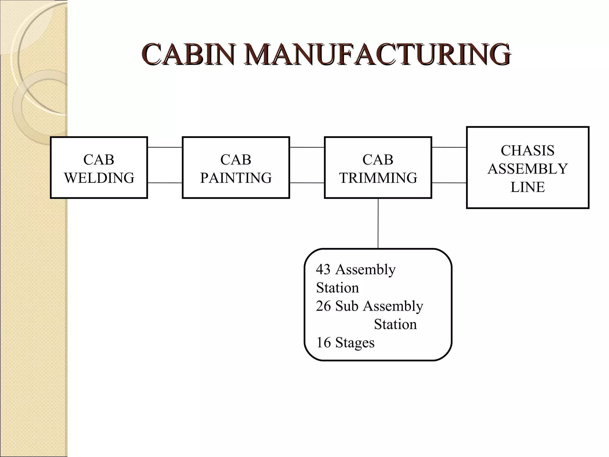
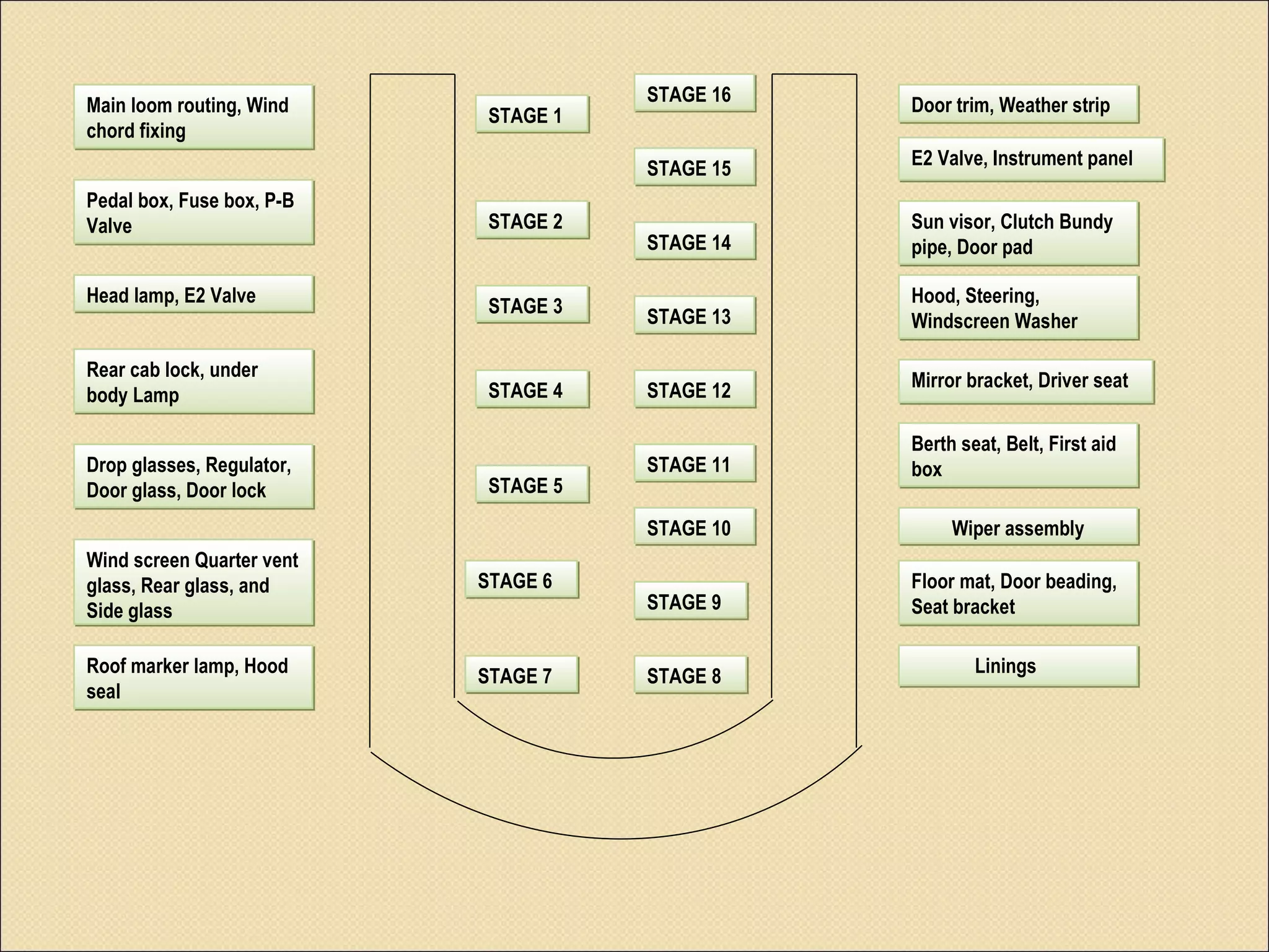
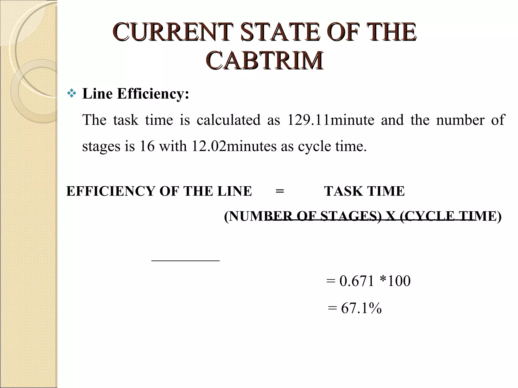
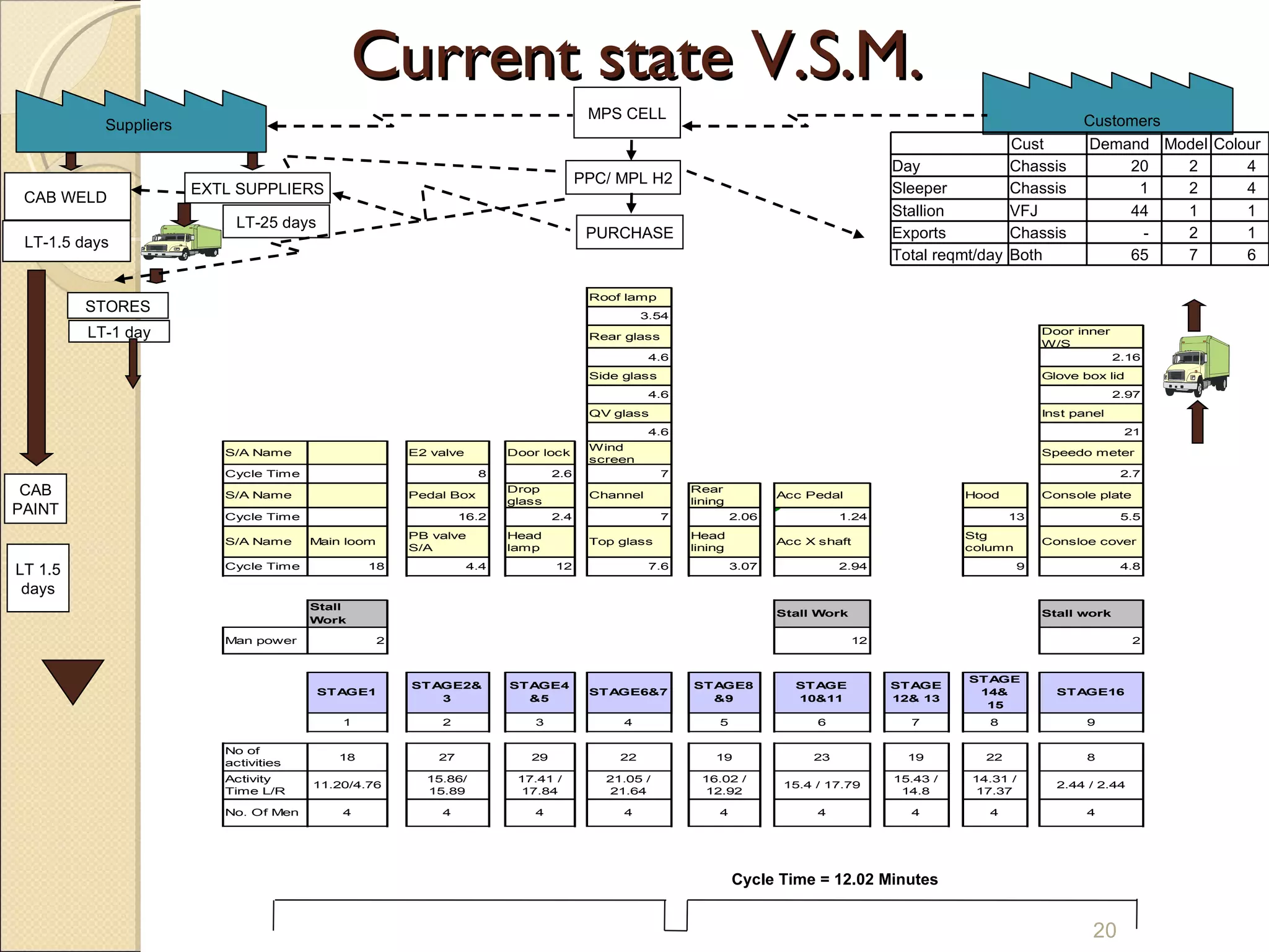
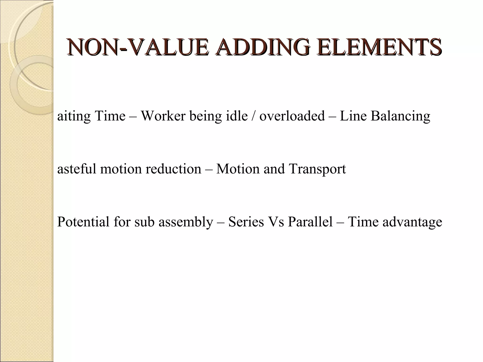
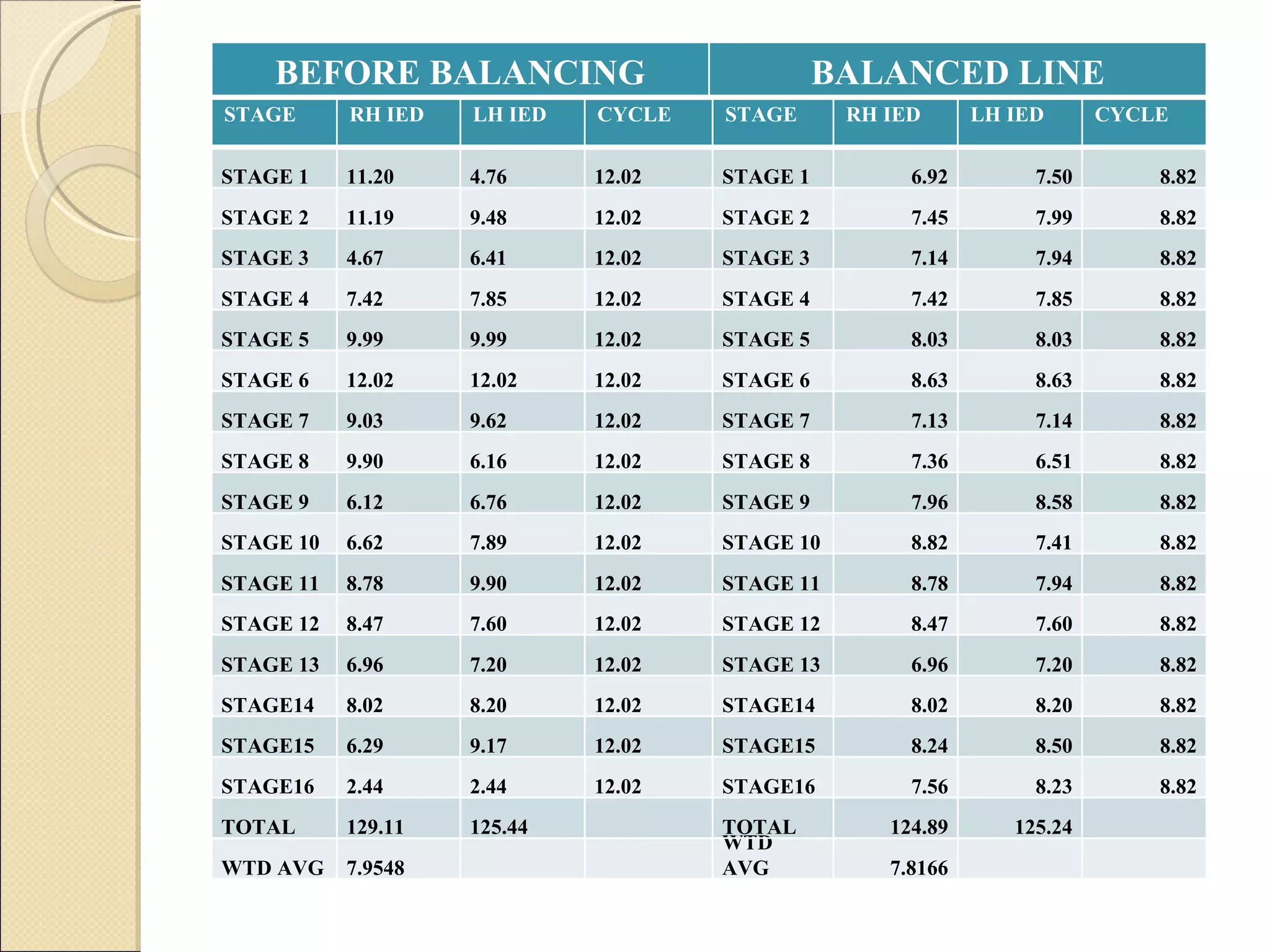
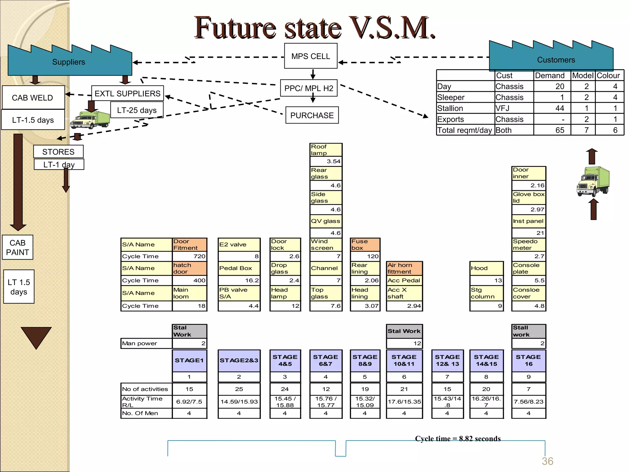
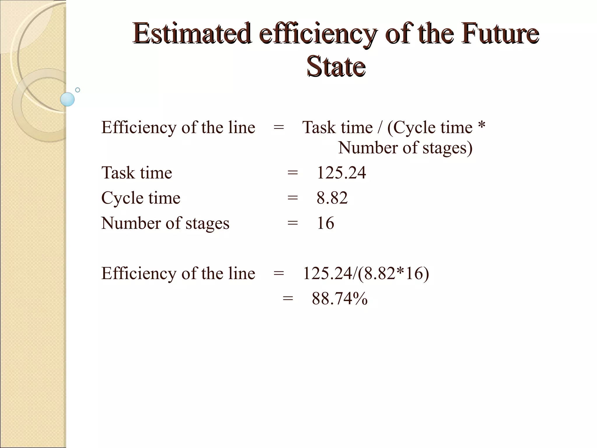
IMPLEMENTATION OF LEAN MANUFACTURING IN CAB TRIM THROUGH V.S.M    M6234 - ADVANCED MANUFACTURING SYSTEM Submitted by ARANGANATHAN SOUNDARARAJAN - G0900691A BHASKARAN RAGHUKARTHIK - G0900695L NATARAJAN KARUPPAIH - G0900707C PRAVEEN KANTHARAJ BALASUBRAMANIAM - G0900718J SANKARANARAYANAN  TYAGGARAJAN - G0900725E SENJIVEL SENTHIL KUMARAN - G0900779E
ABSTRACT The aim was to analyze its current manufacturing system and to propose a more advanced system for its future migration.   From the derived current VSM, we identified the potentials for improvement and implemented the same while mapping the future state VSM. They can be listed as, Unequal distribution of work load – Waiting time High potential for sub assembly in main line Wasteful motion Hence the objective is to increase the production by eliminating the non-value adding activities.
CABIN MANUFACTURING CAB WELDING CAB PAINTING CAB TRIMMING CHASIS ASSEMBLY LINE 43 Assembly Station 26 Sub Assembly  Station  16 Stages
Cabin Manufacturing involves : Cabin welding :  -The various panels get  spot welded  -  cubed  into a shell -  reinforced  to gain strength  -Then they are  MIG welded  and then  moved  to Cab paint shop through an automatic conveyor Cab Painting:  -Here the shell is further  degreased -And  primer coated  by an Electro Deposition painting process and  top coated  with required color
-The cabin is then moved to Waxing zone where the cabin body is PVC coated. Cab Trimming: -The painted shells are  trimmed  in a conveyor line with 43 stations and 26 sub-assembly stations which are grouped into 16 stages.  -Here the cabin gets the real shape -The fully trimmed cabin is picked up for fixing on to the chassis through a  automatic  conveyor arrangement.
CLASSIFICATION OF MODEL CABINS Cargo day cabins Cargo sleeper cabins LHD- day cabins LHD- sleeper cabins Stallion LRV The introduction of Cargo in ABC Ltd product range paved the way to meet company's corporate goal of " Global Standards-Global Markets ".
PRODUCTS MANUFACTURED The wide ranges of products manufactured by ABC Ltd are listed below. 7 Ton GVW to 45 Ton GTW Vehicles 26 To 90 Seated Buses Special Application Vehicles Off highway vehicles Defense support vehicles Diesel Engines for Industrial & Marine Application
SYSTEM ARCHITECTURE IN CAB TRIM Stage 1- Main loom routing, Wind chord fixing Stage 2- Pedal box, Fuse box, P-B Valve Stage 3-Head lamp, E2 Valve Stage 4-Rear cab lock, under body Lamp. Stage 5-Drop glasses, Regulator, Door glass, Door lock. Stage 6- Wind screen Quarter vent glass, Rear glass, and Side glass. Stage 7- Roof marker lamp, Hood seal. Stage 8-Linings
Stage 9-Floormat, Door beading, Seat bracket Stage 10-Wiper assembly Stage 11- Berth seat, Belt, First aid box. Stage 12-Mirror bracket, Driver seat Stage 13-Hood, Steering, Windscreen Washer. Stage 14-Sun visor, Clutch Bundy pipe, Door pad Stage 15-E2 Valve, Instrument panel. Stage 16-Door trim, Weather strip
STAGE 1 STAGE 2 STAGE 3 STAGE 4 STAGE 5 STAGE 6 STAGE 8 STAGE 7 STAGE 16 STAGE 15 STAGE 14 STAGE 13 STAGE 12 STAGE 11 STAGE 10 STAGE 9 Main loom routing, Wind chord fixing Pedal box, Fuse box, P-B Valve Linings Roof marker lamp, Hood seal Wind screen Quarter vent glass, Rear glass, and Side glass Drop glasses, Regulator, Door glass, Door lock Rear cab lock, under body Lamp Head lamp, E2 Valve Door trim, Weather strip E2 Valve, Instrument panel Sun visor, Clutch Bundy pipe, Door pad Hood, Steering, Windscreen Washer Mirror bracket, Driver seat Berth seat, Belt, First aid box Wiper assembly Floor mat, Door beading, Seat bracket
OBJECTIVE OF THE PROJECT Implementing Lean manufacturing tool, VSM to identify the Non value adding activities To handle various models with varying work content To finish the cabin in the line itself To enable the line to produce fully built quality cabins To improve the overall efficiency of the line To distribute the work load equally to all stages
METHODOLOGY Study the current flow of material and information available in the shop by value stream mapping. Identify the losses due to unwanted/Non value adding activities. Plan actions to reduce unwanted activities by Lean manufacturing technique. Balance the line to improve productivity. Suggest recommendations to reach the target by using various Lean tools to lean the line.
WHAT IS VSM ??? Value Stream Mapping , a powerful tool used to map out both the material and information flow.  The flow of the product from start to finish is the value stream including all value added and non value added actions.  This includes action to process information from the customer and actions to transform the products on its way to customer. It is also known as  Material Information Flow Analysis .
It is a simple diagram in a single page - a product path from order to delivery. VSM begins its journey with the current state MIFA . And it ends with the future state MIFA. Using VSM we can stream line work processes - cutting lead time and operating costs.  A future state MIFA shows the opportunity for improvement - to achieve a higher level of performance.
BENEFITS OF VSM Identify the flow of value stream and identify the waste. All products are viewed from an overall system perspective. Draw both material and information flow of the value stream. Draw a blue print for lean transformation. Prioritize the activities needed to achieve the future state.
SYMBOLS IN VSM   Movement of  goods    Outside Source   Lorry Movement   from supplier to    customer   Manufacturing    Pull Arrow   Push Arrow Process Company Name 1 per week  250 per box Assemb l
Inventory controlled by location, quantity and replenishment method 3000 First in First out    Uncontrolled  sequence Shop stock inventory Electronic Information flow     Data box FIFO C/T  = SHIFTS  = C/O
PROCEDURE FOR VSM The steps to map Value Stream are : Define Customer Requirement Draw Process step Gather Process Data Explains the external Material Flow Explains the internal Material and Information Flow Lead Time Hints
CURRENT STATE OF THE CABTRIM Line Efficiency: The task time is calculated as 129.11minute and the number of stages is 16 with 12.02minutes as cycle time.  EFFICIENCY OF THE LINE    =  TASK TIME    (NUMBER OF STAGES) X (CYCLE TIME)         = 0.671 *100     = 67.1%
Current state V.S.M. CAB WELD  EXTL SUPPLIERS LT-1.5 days LT-25 days CAB PAINT STORES Suppliers LT 1.5 days LT-1 day MPS CELL Customers PPC/ MPL H2 PURCHASE Cycle Time = 12.02 Minutes Cust Demand Model  Colour Day Chassis 20 2 4 Sleeper Chassis 1 2 4 Stallion VFJ 44 1 1 Exports Chassis - 2 1 Total reqmt/day Both 65 7 6
NON-VALUE ADDING ELEMENTS Waiting Time – Worker being idle / overloaded – Line Balancing Wasteful motion reduction – Motion and Transport  Potential for sub assembly – Series Vs Parallel – Time advantage
WAITING TIME The work in these stages is needed to be distributed to avoid unnecessary waiting of some workers and over loading of some other workers.  To avoid this we should concentrate on  Line balancing .  Loom inserting and routing Capacitor fitment Fuse box guard fitment Door beading fitment
Line Balancing: It stands for balancing the production line or an assembly line.  Aims at grouping the facilities and workers in an efficient pattern - to obtain an optimum or most promising balance of the capacities and flow of the production or assembly processes. Tasks are grouped so that their total time is preferably equal to or little lesser than the time available at each workstation – this reduces the idle time. There are two basic concepts of assigning works to the stations. They are, Permeability of Tasks Lateral transferability of tasks
STAGE RH IED LH IED CYCLE STAGE RH IED LH IED CYCLE STAGE 1 11.20 4.76 12.02 STAGE 1 6.92 7.50 8.82 STAGE 2 11.19 9.48 12.02 STAGE 2 7.45 7.99 8.82 STAGE 3 4.67 6.41 12.02 STAGE 3 7.14 7.94 8.82 STAGE 4 7.42 7.85 12.02 STAGE 4 7.42 7.85 8.82 STAGE 5 9.99 9.99 12.02 STAGE 5 8.03 8.03 8.82 STAGE 6 12.02 12.02 12.02 STAGE 6 8.63 8.63 8.82 STAGE 7 9.03 9.62 12.02 STAGE 7 7.13 7.14 8.82 STAGE 8 9.90 6.16 12.02 STAGE 8 7.36 6.51 8.82 STAGE 9 6.12 6.76 12.02 STAGE 9 7.96 8.58 8.82 STAGE 10 6.62 7.89 12.02 STAGE 10 8.82 7.41 8.82 STAGE 11 8.78 9.90 12.02 STAGE 11 8.78 7.94 8.82 STAGE 12 8.47 7.60 12.02 STAGE 12 8.47 7.60 8.82 STAGE 13 6.96 7.20 12.02 STAGE 13 6.96 7.20 8.82 STAGE14 8.02 8.20 12.02 STAGE14 8.02 8.20 8.82 STAGE15 6.29 9.17 12.02 STAGE15 8.24 8.50 8.82 STAGE16 2.44 2.44 12.02 STAGE16 7.56 8.23 8.82 TOTAL 129.11 125.44   TOTAL 124.89 125.24   WTD AVG 7.9548     WTD AVG 7.8166     BEFORE BALANCING BALANCED LINE
WASTEFUL MOTION REDUCTION In the 16 stages the cabin assembly takes a lot of wasteful motion and transport which are identified by observing the activities, distance between the parts and line observed by the time and motion study. Some of the activities having wasteful motions are : Removal of hood and placed in trolley Control rod fitment Dummy plug and cage nut fitment Windshield fitment Berth seat and back rest fitment
Removal of hood and placed in trolley: -Hood is a part in front side of the cabin.  -It is removed in the first stage for doing other operations and to replace it the worker has to walk for some 4 meter which takes 15 seconds.  -Distance can be reduced to 1 meter so that the time reduces by 5 seconds. Control rod fitment : -Control rod fits on the backside of the cabin.  -It is 5 meter away from the line which consumes up to 30 seconds to walk.
-So in order to eliminate the wastage of time, it is recommended to place at a distance of 1 meter in a feasible way that consumes only 5 seconds. Dummy plug and cage nut fitment: -These activities are carried out in more than 3 stages.  -For the fitment of dummy plug and cage nut, workers need to move  some distance which may vary in each case.  -These movements can be avoided by providing a kit that is having those small parts, in the line itself with the cabin.
Windshield fitment: -Windshield is the front glass fitted in the cabin which has to be handled with care.  -Most of the scraping in windshield occurs while handling only -This can be eliminated by providing a pneumatic device for holding the glass.
POTENTIAL FOR SUB ASSEMBLY Some activities that carried out on the Cab trim line can be done as the sub assembly because it can stand as the constraint for the productivity improvement. Some of such activities are Air horn fitment Hatch door lock, pad, and magnet fitment  Fuse box guard fitment Door
Air Horn Fitment:  -In the air horn assembling, it needs to be assembling with a hose, and a clamp for the fitment. -These two fitments itself takes more than 45 seconds.  -If we transfer it to the sub assembly or buy it as the assembled part, we can reduce this time and work load. Hatch door lock, pad, and magnet fitment: - Hatch door is in the top of the vehicle provided for stallion vehicles.   -It is provided in such a way that can be opened from inside it.
  - lock pad and a magnet. - Fitment of these three parts consumes more than 400 seconds. - If we move it to sub assembly we can save such a significant amount of time. Hence the productivity will increase. Fuse Box guard fitment:   -The fuse box guard is assembled with a valve and fitted on the high level II. This valve is for providing coolant supply to the demister.  -Assembling of this valve in the line itself consumes some 120 seconds. -This can be done in the sub assembly or can buy it as the valve fixed fuse box guard from the supplier.
Door :  -The 2 doors of the cabin have works in two stages. Glass assembly and Door trim. In Glass assembly it needs to assemble, Drop glass Door top glass Quarter vent glass Door lock fitment Regulator fitment
Channel fitment Door glass beading fitment In Door trim it needs to do, Grease application Remote lock fitment Control rod fitment Tape sticking and door seal sticking Door pad fitment Door handle fitment
Regulator handle fitment Door belt inner weather strip fitment These activities consumes totally 360 seconds for each door in each stage. Hence if we move all these activities to sub assembly, we can save 720 seconds on each side, by this we can eliminate two or at least one stage.
A thorough study was done throughout the line stage by stage to understand the various factors that contribute for productivity.  Due to large idle time, the cycle time was as high as 12.02 minutes. The Line efficiency was only 67.1%. We identified lots of improvement potentials. Mainly the unbalanced line, wasteful motions, high potential for sub assembly were the constraints identified.  By eliminating or modifying the non value adding elements, we arrived the future state VSM.
Future state V.S.M. CAB WELD  EXTL SUPPLIERS LT-1.5 days LT-25 days CAB PAINT STORES Suppliers LT 1.5 days LT-1 day MPS CELL Customers PPC/ MPL H2 PURCHASE Cycle time = 8.82 seconds Cust Demand Model  Colour Day Chassis 20 2 4 Sleeper Chassis 1 2 4 Stallion VFJ 44 1 1 Exports Chassis - 2 1 Total reqmt/day Both 65 7 6
Estimated efficiency of the Future State Efficiency of the line  =  Task time / (Cycle time *  Number of stages) Task time     =  125.24 Cycle time     =  8.82 Number of stages   =  16 Efficiency of the line  =  125.24/(8.82*16)    =  88.74%
CONCLUSION Current VSM has been mapped Non value added activities such as Waiting, wasteful motion, potential for sub assembly were identified Line balancing has been suggested in order to reduce the  waiting time  In turn the efficiency of the line has increased to 88.74%
Thank You

Final ams power_point_slides-------newwww

  • 1.
    IMPLEMENTATION OF LEANMANUFACTURING IN CAB TRIM THROUGH V.S.M   M6234 - ADVANCED MANUFACTURING SYSTEM Submitted by ARANGANATHAN SOUNDARARAJAN - G0900691A BHASKARAN RAGHUKARTHIK - G0900695L NATARAJAN KARUPPAIH - G0900707C PRAVEEN KANTHARAJ BALASUBRAMANIAM - G0900718J SANKARANARAYANAN TYAGGARAJAN - G0900725E SENJIVEL SENTHIL KUMARAN - G0900779E
  • 2.
    ABSTRACT The aimwas to analyze its current manufacturing system and to propose a more advanced system for its future migration. From the derived current VSM, we identified the potentials for improvement and implemented the same while mapping the future state VSM. They can be listed as, Unequal distribution of work load – Waiting time High potential for sub assembly in main line Wasteful motion Hence the objective is to increase the production by eliminating the non-value adding activities.
  • 3.
    CABIN MANUFACTURING CABWELDING CAB PAINTING CAB TRIMMING CHASIS ASSEMBLY LINE 43 Assembly Station 26 Sub Assembly Station 16 Stages
  • 4.
    Cabin Manufacturing involves: Cabin welding : -The various panels get spot welded - cubed into a shell - reinforced to gain strength -Then they are MIG welded and then moved to Cab paint shop through an automatic conveyor Cab Painting: -Here the shell is further degreased -And primer coated by an Electro Deposition painting process and top coated with required color
  • 5.
    -The cabin isthen moved to Waxing zone where the cabin body is PVC coated. Cab Trimming: -The painted shells are trimmed in a conveyor line with 43 stations and 26 sub-assembly stations which are grouped into 16 stages. -Here the cabin gets the real shape -The fully trimmed cabin is picked up for fixing on to the chassis through a automatic conveyor arrangement.
  • 6.
    CLASSIFICATION OF MODELCABINS Cargo day cabins Cargo sleeper cabins LHD- day cabins LHD- sleeper cabins Stallion LRV The introduction of Cargo in ABC Ltd product range paved the way to meet company's corporate goal of " Global Standards-Global Markets ".
  • 7.
    PRODUCTS MANUFACTURED Thewide ranges of products manufactured by ABC Ltd are listed below. 7 Ton GVW to 45 Ton GTW Vehicles 26 To 90 Seated Buses Special Application Vehicles Off highway vehicles Defense support vehicles Diesel Engines for Industrial & Marine Application
  • 8.
    SYSTEM ARCHITECTURE INCAB TRIM Stage 1- Main loom routing, Wind chord fixing Stage 2- Pedal box, Fuse box, P-B Valve Stage 3-Head lamp, E2 Valve Stage 4-Rear cab lock, under body Lamp. Stage 5-Drop glasses, Regulator, Door glass, Door lock. Stage 6- Wind screen Quarter vent glass, Rear glass, and Side glass. Stage 7- Roof marker lamp, Hood seal. Stage 8-Linings
  • 9.
    Stage 9-Floormat, Doorbeading, Seat bracket Stage 10-Wiper assembly Stage 11- Berth seat, Belt, First aid box. Stage 12-Mirror bracket, Driver seat Stage 13-Hood, Steering, Windscreen Washer. Stage 14-Sun visor, Clutch Bundy pipe, Door pad Stage 15-E2 Valve, Instrument panel. Stage 16-Door trim, Weather strip
  • 10.
    STAGE 1 STAGE2 STAGE 3 STAGE 4 STAGE 5 STAGE 6 STAGE 8 STAGE 7 STAGE 16 STAGE 15 STAGE 14 STAGE 13 STAGE 12 STAGE 11 STAGE 10 STAGE 9 Main loom routing, Wind chord fixing Pedal box, Fuse box, P-B Valve Linings Roof marker lamp, Hood seal Wind screen Quarter vent glass, Rear glass, and Side glass Drop glasses, Regulator, Door glass, Door lock Rear cab lock, under body Lamp Head lamp, E2 Valve Door trim, Weather strip E2 Valve, Instrument panel Sun visor, Clutch Bundy pipe, Door pad Hood, Steering, Windscreen Washer Mirror bracket, Driver seat Berth seat, Belt, First aid box Wiper assembly Floor mat, Door beading, Seat bracket
  • 11.
    OBJECTIVE OF THEPROJECT Implementing Lean manufacturing tool, VSM to identify the Non value adding activities To handle various models with varying work content To finish the cabin in the line itself To enable the line to produce fully built quality cabins To improve the overall efficiency of the line To distribute the work load equally to all stages
  • 12.
    METHODOLOGY Study thecurrent flow of material and information available in the shop by value stream mapping. Identify the losses due to unwanted/Non value adding activities. Plan actions to reduce unwanted activities by Lean manufacturing technique. Balance the line to improve productivity. Suggest recommendations to reach the target by using various Lean tools to lean the line.
  • 13.
    WHAT IS VSM??? Value Stream Mapping , a powerful tool used to map out both the material and information flow. The flow of the product from start to finish is the value stream including all value added and non value added actions. This includes action to process information from the customer and actions to transform the products on its way to customer. It is also known as Material Information Flow Analysis .
  • 14.
    It is asimple diagram in a single page - a product path from order to delivery. VSM begins its journey with the current state MIFA . And it ends with the future state MIFA. Using VSM we can stream line work processes - cutting lead time and operating costs. A future state MIFA shows the opportunity for improvement - to achieve a higher level of performance.
  • 15.
    BENEFITS OF VSMIdentify the flow of value stream and identify the waste. All products are viewed from an overall system perspective. Draw both material and information flow of the value stream. Draw a blue print for lean transformation. Prioritize the activities needed to achieve the future state.
  • 16.
    SYMBOLS IN VSM Movement of goods Outside Source Lorry Movement from supplier to customer Manufacturing Pull Arrow Push Arrow Process Company Name 1 per week 250 per box Assemb l
  • 17.
    Inventory controlled bylocation, quantity and replenishment method 3000 First in First out Uncontrolled sequence Shop stock inventory Electronic Information flow Data box FIFO C/T = SHIFTS = C/O
  • 18.
    PROCEDURE FOR VSMThe steps to map Value Stream are : Define Customer Requirement Draw Process step Gather Process Data Explains the external Material Flow Explains the internal Material and Information Flow Lead Time Hints
  • 19.
    CURRENT STATE OFTHE CABTRIM Line Efficiency: The task time is calculated as 129.11minute and the number of stages is 16 with 12.02minutes as cycle time. EFFICIENCY OF THE LINE = TASK TIME (NUMBER OF STAGES) X (CYCLE TIME) = 0.671 *100 = 67.1%
  • 20.
    Current state V.S.M.CAB WELD EXTL SUPPLIERS LT-1.5 days LT-25 days CAB PAINT STORES Suppliers LT 1.5 days LT-1 day MPS CELL Customers PPC/ MPL H2 PURCHASE Cycle Time = 12.02 Minutes Cust Demand Model Colour Day Chassis 20 2 4 Sleeper Chassis 1 2 4 Stallion VFJ 44 1 1 Exports Chassis - 2 1 Total reqmt/day Both 65 7 6
  • 21.
    NON-VALUE ADDING ELEMENTSWaiting Time – Worker being idle / overloaded – Line Balancing Wasteful motion reduction – Motion and Transport Potential for sub assembly – Series Vs Parallel – Time advantage
  • 22.
    WAITING TIME Thework in these stages is needed to be distributed to avoid unnecessary waiting of some workers and over loading of some other workers. To avoid this we should concentrate on Line balancing . Loom inserting and routing Capacitor fitment Fuse box guard fitment Door beading fitment
  • 23.
    Line Balancing: Itstands for balancing the production line or an assembly line. Aims at grouping the facilities and workers in an efficient pattern - to obtain an optimum or most promising balance of the capacities and flow of the production or assembly processes. Tasks are grouped so that their total time is preferably equal to or little lesser than the time available at each workstation – this reduces the idle time. There are two basic concepts of assigning works to the stations. They are, Permeability of Tasks Lateral transferability of tasks
  • 24.
    STAGE RH IEDLH IED CYCLE STAGE RH IED LH IED CYCLE STAGE 1 11.20 4.76 12.02 STAGE 1 6.92 7.50 8.82 STAGE 2 11.19 9.48 12.02 STAGE 2 7.45 7.99 8.82 STAGE 3 4.67 6.41 12.02 STAGE 3 7.14 7.94 8.82 STAGE 4 7.42 7.85 12.02 STAGE 4 7.42 7.85 8.82 STAGE 5 9.99 9.99 12.02 STAGE 5 8.03 8.03 8.82 STAGE 6 12.02 12.02 12.02 STAGE 6 8.63 8.63 8.82 STAGE 7 9.03 9.62 12.02 STAGE 7 7.13 7.14 8.82 STAGE 8 9.90 6.16 12.02 STAGE 8 7.36 6.51 8.82 STAGE 9 6.12 6.76 12.02 STAGE 9 7.96 8.58 8.82 STAGE 10 6.62 7.89 12.02 STAGE 10 8.82 7.41 8.82 STAGE 11 8.78 9.90 12.02 STAGE 11 8.78 7.94 8.82 STAGE 12 8.47 7.60 12.02 STAGE 12 8.47 7.60 8.82 STAGE 13 6.96 7.20 12.02 STAGE 13 6.96 7.20 8.82 STAGE14 8.02 8.20 12.02 STAGE14 8.02 8.20 8.82 STAGE15 6.29 9.17 12.02 STAGE15 8.24 8.50 8.82 STAGE16 2.44 2.44 12.02 STAGE16 7.56 8.23 8.82 TOTAL 129.11 125.44   TOTAL 124.89 125.24   WTD AVG 7.9548     WTD AVG 7.8166     BEFORE BALANCING BALANCED LINE
  • 25.
    WASTEFUL MOTION REDUCTIONIn the 16 stages the cabin assembly takes a lot of wasteful motion and transport which are identified by observing the activities, distance between the parts and line observed by the time and motion study. Some of the activities having wasteful motions are : Removal of hood and placed in trolley Control rod fitment Dummy plug and cage nut fitment Windshield fitment Berth seat and back rest fitment
  • 26.
    Removal of hoodand placed in trolley: -Hood is a part in front side of the cabin. -It is removed in the first stage for doing other operations and to replace it the worker has to walk for some 4 meter which takes 15 seconds. -Distance can be reduced to 1 meter so that the time reduces by 5 seconds. Control rod fitment : -Control rod fits on the backside of the cabin. -It is 5 meter away from the line which consumes up to 30 seconds to walk.
  • 27.
    -So in orderto eliminate the wastage of time, it is recommended to place at a distance of 1 meter in a feasible way that consumes only 5 seconds. Dummy plug and cage nut fitment: -These activities are carried out in more than 3 stages. -For the fitment of dummy plug and cage nut, workers need to move some distance which may vary in each case. -These movements can be avoided by providing a kit that is having those small parts, in the line itself with the cabin.
  • 28.
    Windshield fitment: -Windshieldis the front glass fitted in the cabin which has to be handled with care. -Most of the scraping in windshield occurs while handling only -This can be eliminated by providing a pneumatic device for holding the glass.
  • 29.
    POTENTIAL FOR SUBASSEMBLY Some activities that carried out on the Cab trim line can be done as the sub assembly because it can stand as the constraint for the productivity improvement. Some of such activities are Air horn fitment Hatch door lock, pad, and magnet fitment Fuse box guard fitment Door
  • 30.
    Air Horn Fitment: -In the air horn assembling, it needs to be assembling with a hose, and a clamp for the fitment. -These two fitments itself takes more than 45 seconds. -If we transfer it to the sub assembly or buy it as the assembled part, we can reduce this time and work load. Hatch door lock, pad, and magnet fitment: - Hatch door is in the top of the vehicle provided for stallion vehicles. -It is provided in such a way that can be opened from inside it.
  • 31.
    -lock pad and a magnet. - Fitment of these three parts consumes more than 400 seconds. - If we move it to sub assembly we can save such a significant amount of time. Hence the productivity will increase. Fuse Box guard fitment: -The fuse box guard is assembled with a valve and fitted on the high level II. This valve is for providing coolant supply to the demister. -Assembling of this valve in the line itself consumes some 120 seconds. -This can be done in the sub assembly or can buy it as the valve fixed fuse box guard from the supplier.
  • 32.
    Door : -The 2 doors of the cabin have works in two stages. Glass assembly and Door trim. In Glass assembly it needs to assemble, Drop glass Door top glass Quarter vent glass Door lock fitment Regulator fitment
  • 33.
    Channel fitment Doorglass beading fitment In Door trim it needs to do, Grease application Remote lock fitment Control rod fitment Tape sticking and door seal sticking Door pad fitment Door handle fitment
  • 34.
    Regulator handle fitmentDoor belt inner weather strip fitment These activities consumes totally 360 seconds for each door in each stage. Hence if we move all these activities to sub assembly, we can save 720 seconds on each side, by this we can eliminate two or at least one stage.
  • 35.
    A thorough studywas done throughout the line stage by stage to understand the various factors that contribute for productivity. Due to large idle time, the cycle time was as high as 12.02 minutes. The Line efficiency was only 67.1%. We identified lots of improvement potentials. Mainly the unbalanced line, wasteful motions, high potential for sub assembly were the constraints identified. By eliminating or modifying the non value adding elements, we arrived the future state VSM.
  • 36.
    Future state V.S.M.CAB WELD EXTL SUPPLIERS LT-1.5 days LT-25 days CAB PAINT STORES Suppliers LT 1.5 days LT-1 day MPS CELL Customers PPC/ MPL H2 PURCHASE Cycle time = 8.82 seconds Cust Demand Model Colour Day Chassis 20 2 4 Sleeper Chassis 1 2 4 Stallion VFJ 44 1 1 Exports Chassis - 2 1 Total reqmt/day Both 65 7 6
  • 37.
    Estimated efficiency ofthe Future State Efficiency of the line = Task time / (Cycle time * Number of stages) Task time = 125.24 Cycle time = 8.82 Number of stages = 16 Efficiency of the line = 125.24/(8.82*16) = 88.74%
  • 38.
    CONCLUSION Current VSMhas been mapped Non value added activities such as Waiting, wasteful motion, potential for sub assembly were identified Line balancing has been suggested in order to reduce the waiting time In turn the efficiency of the line has increased to 88.74%
  • 39.