The document discusses crystal lattices and crystallography concepts including:
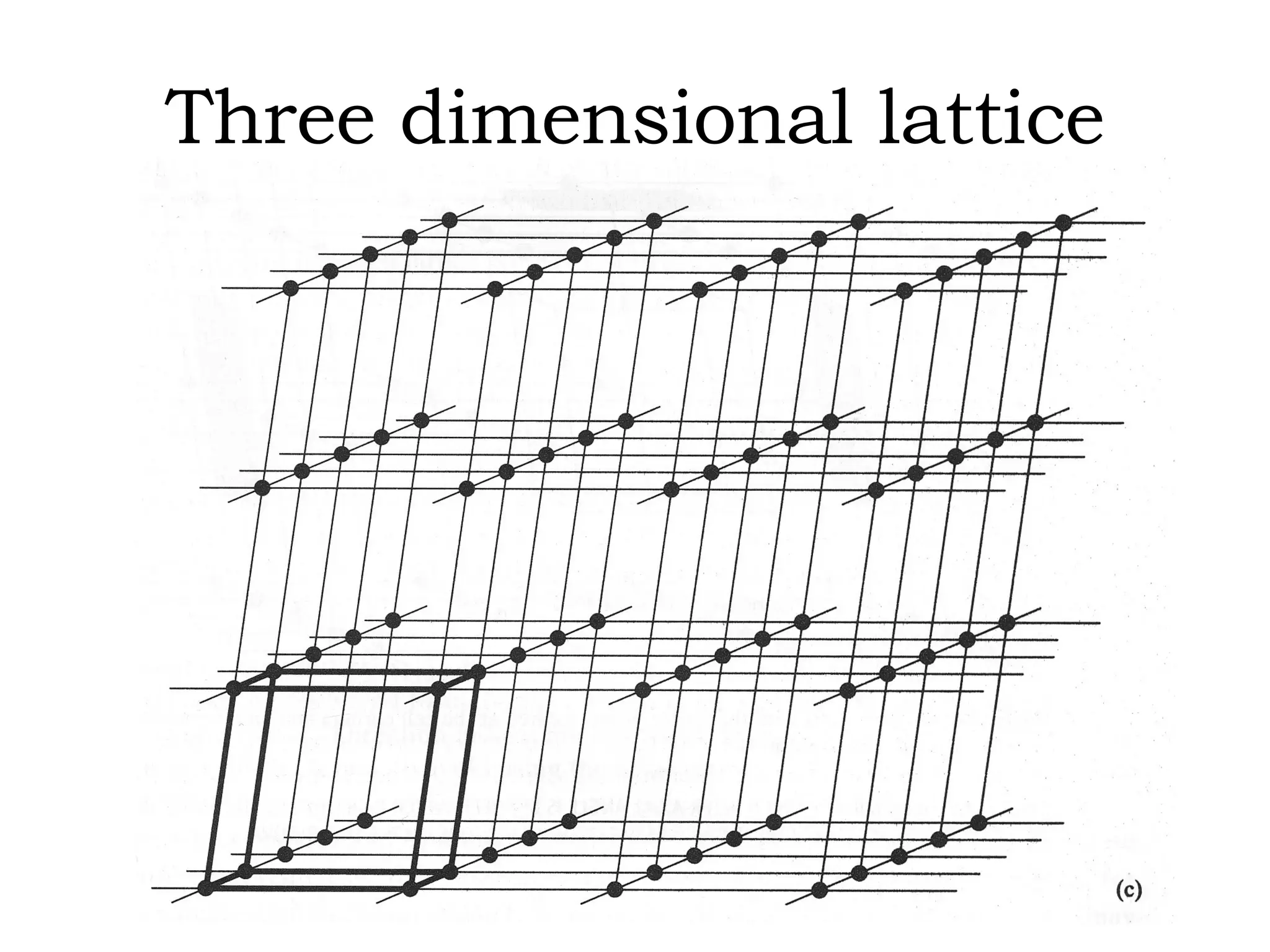
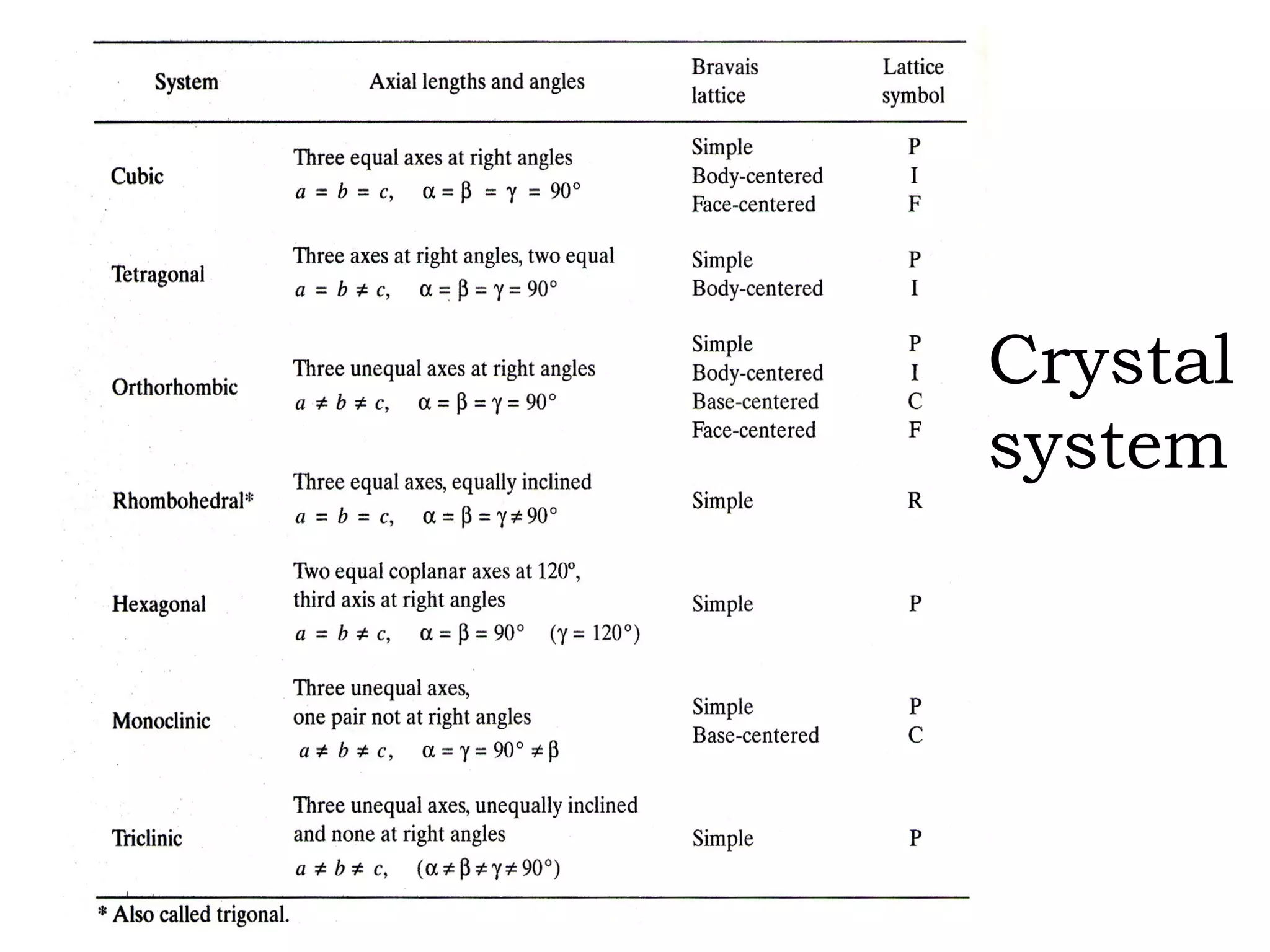
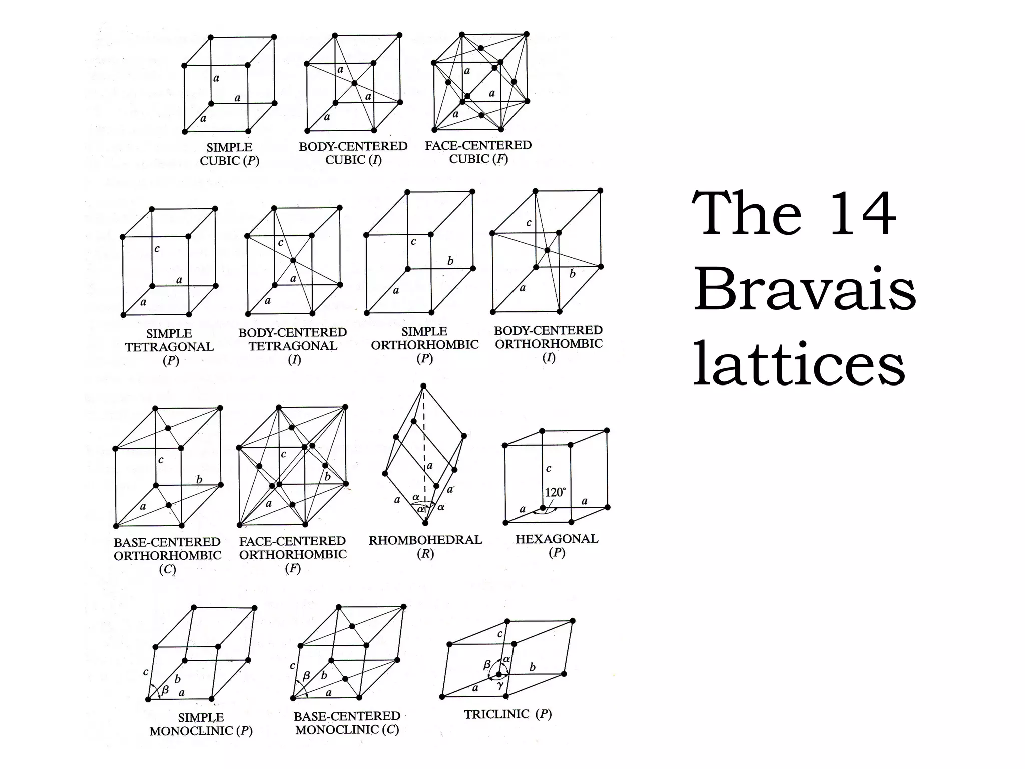
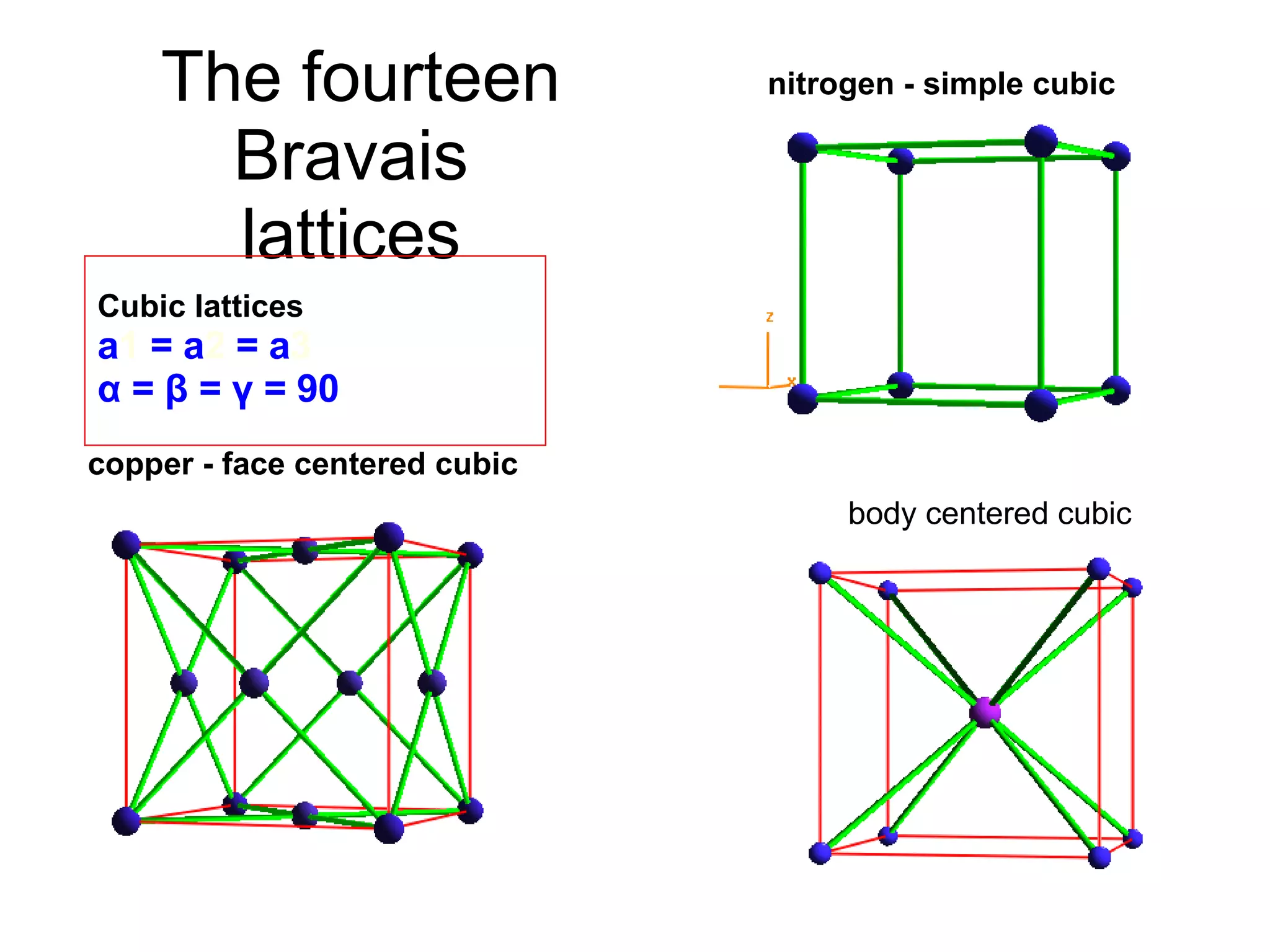
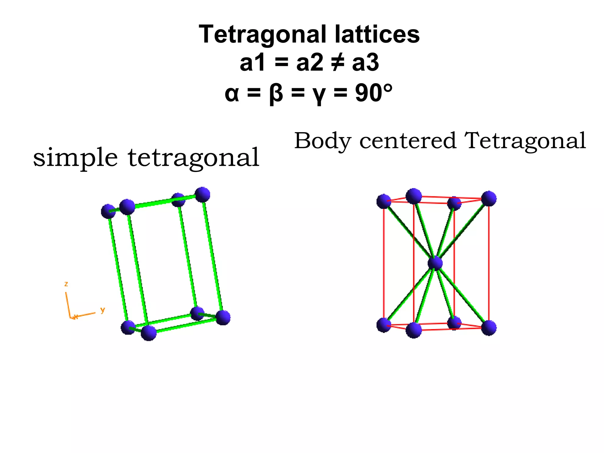
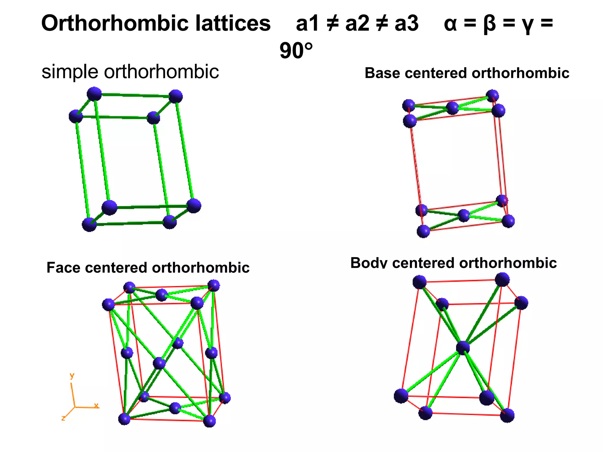
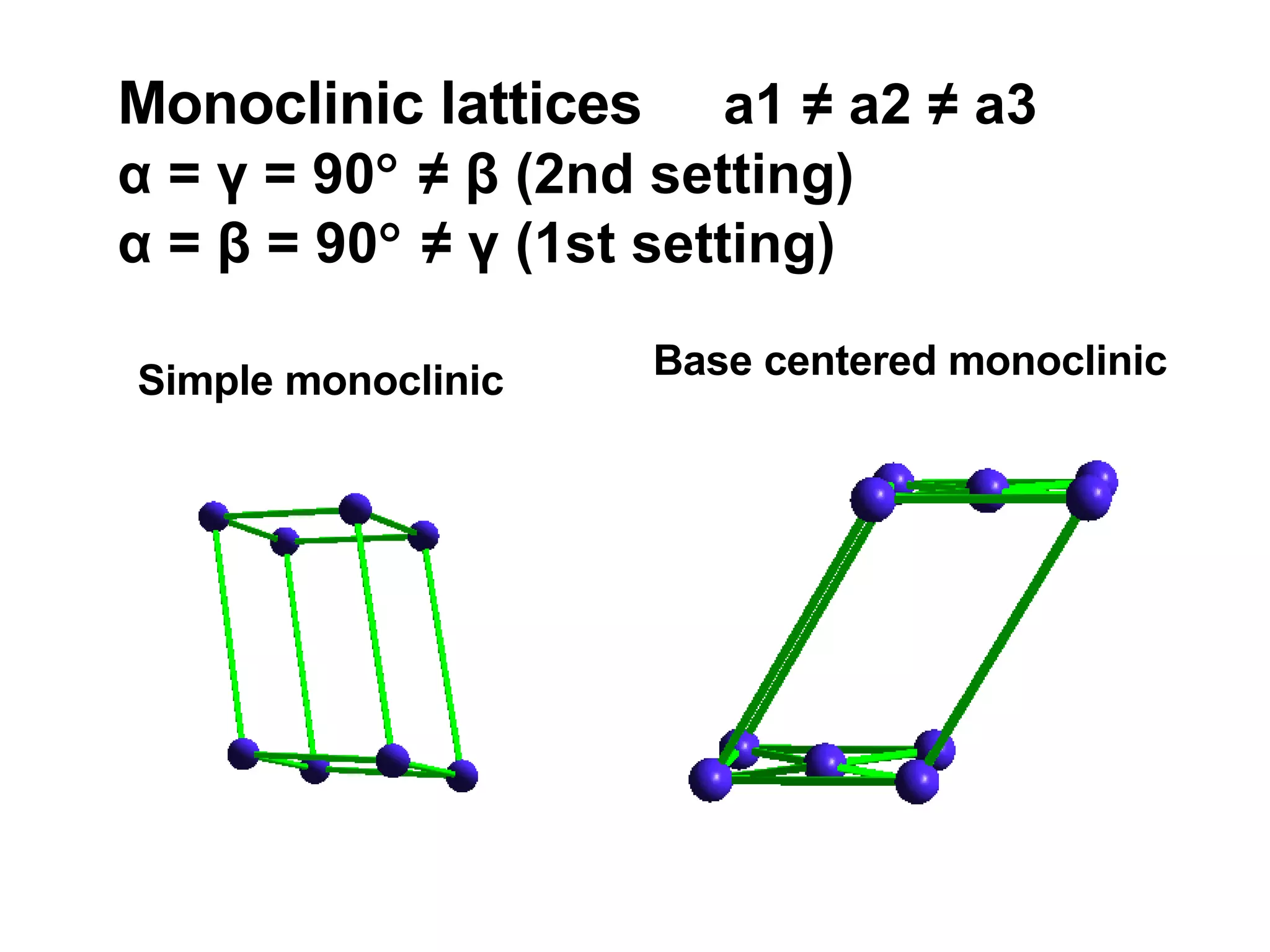
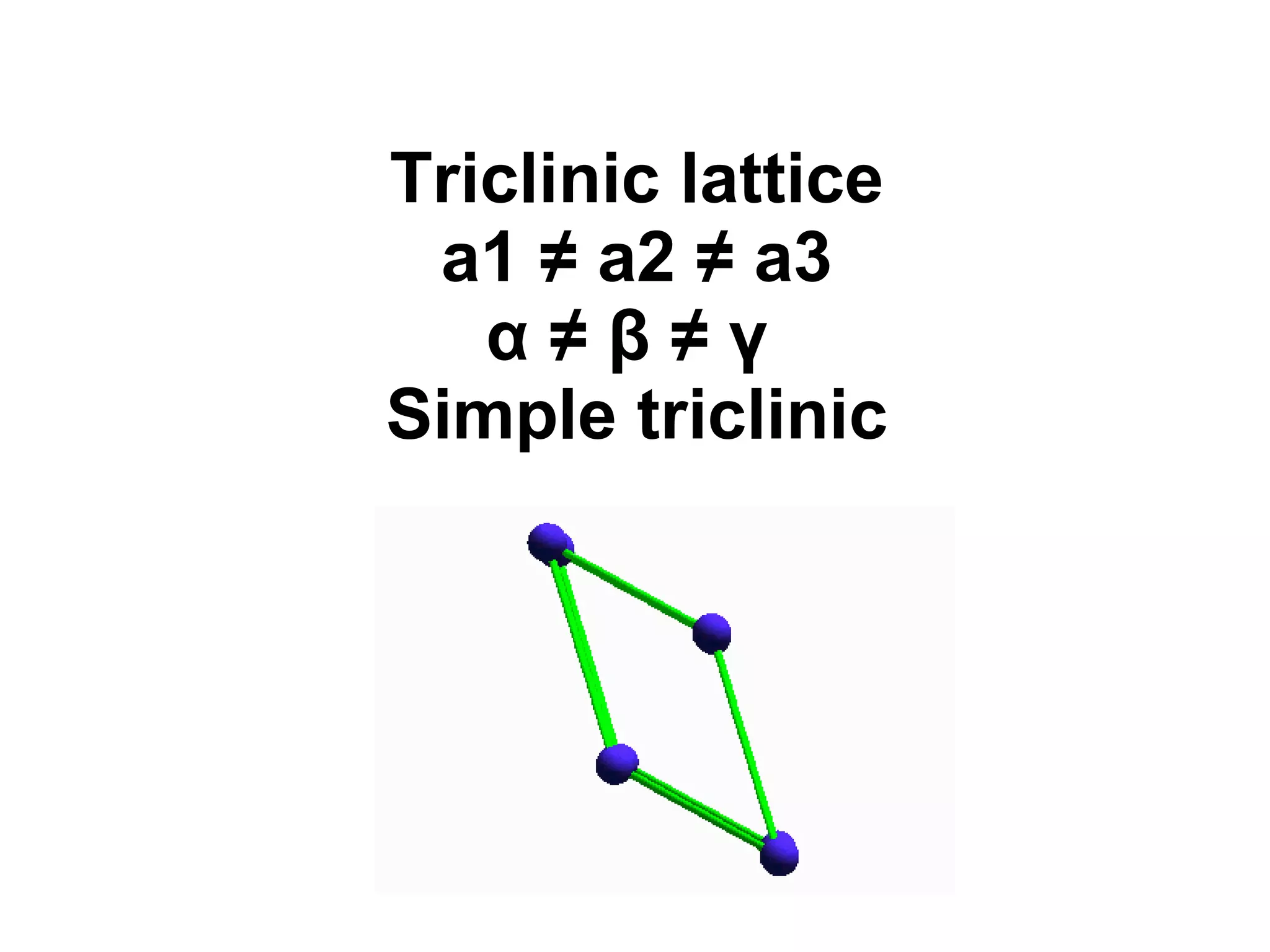
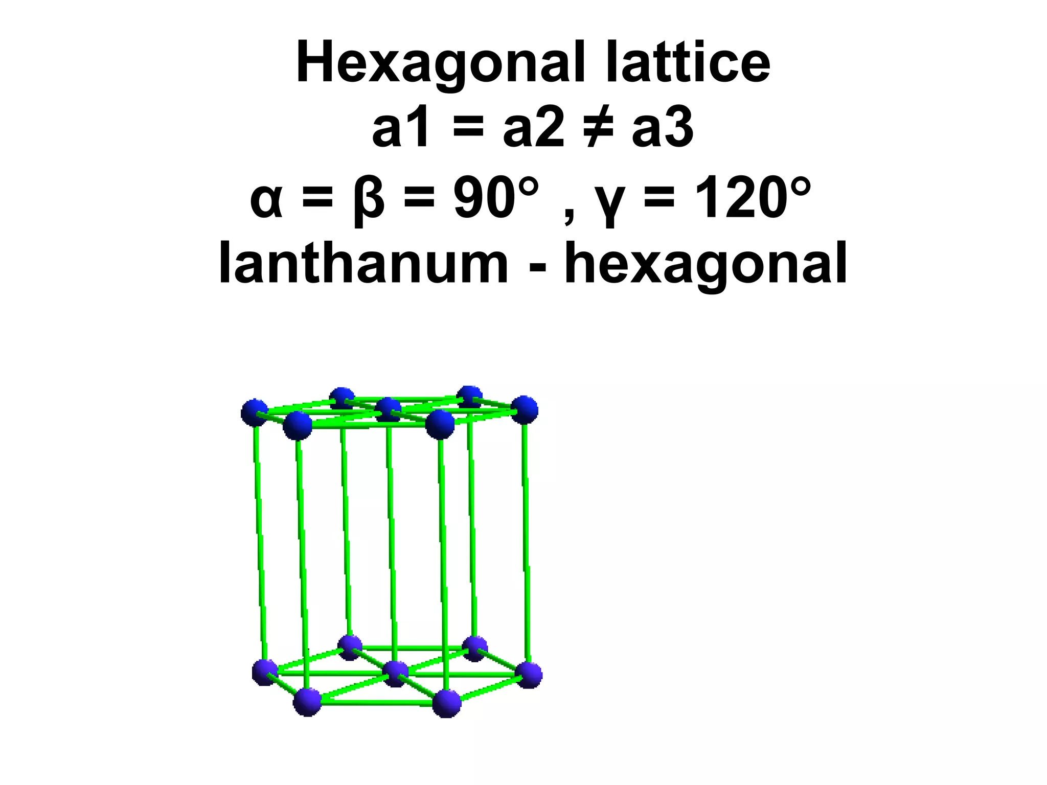
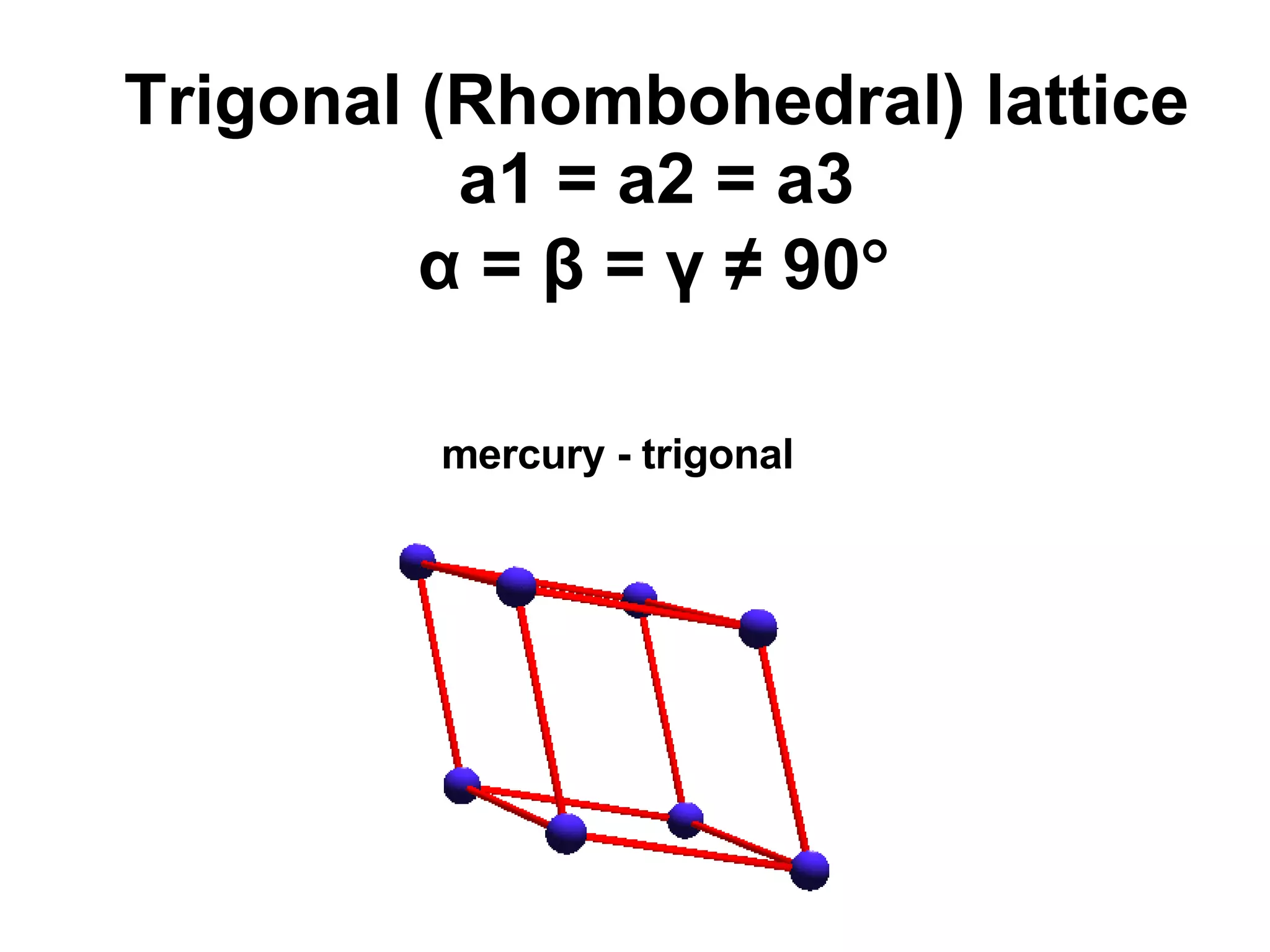
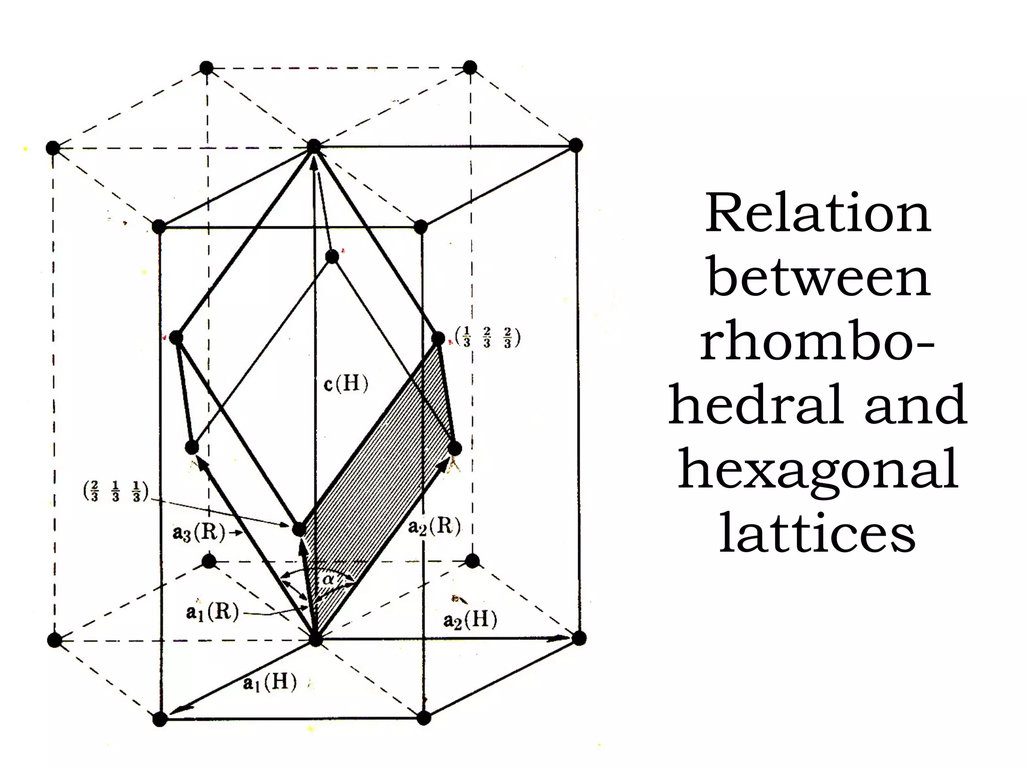
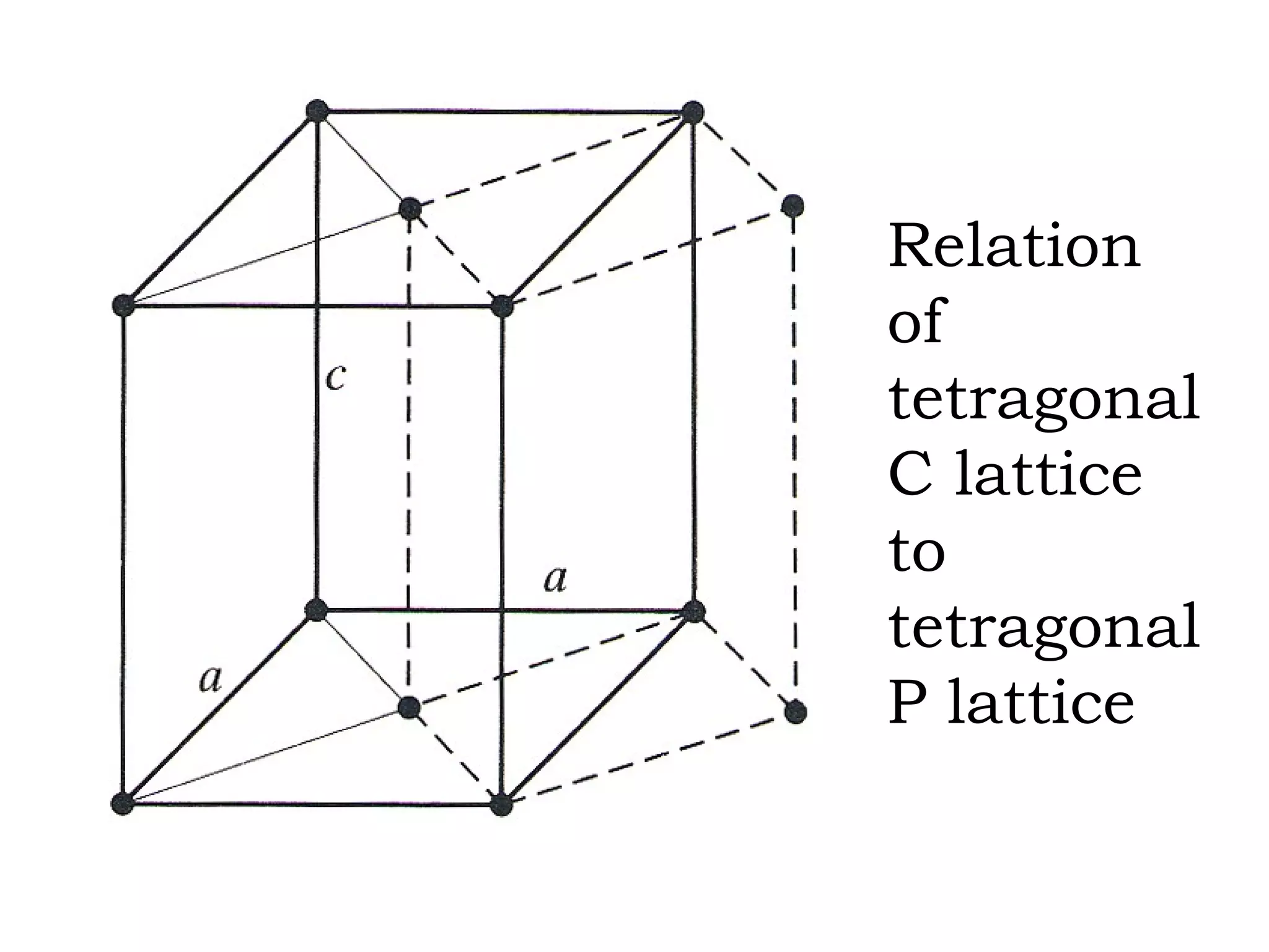
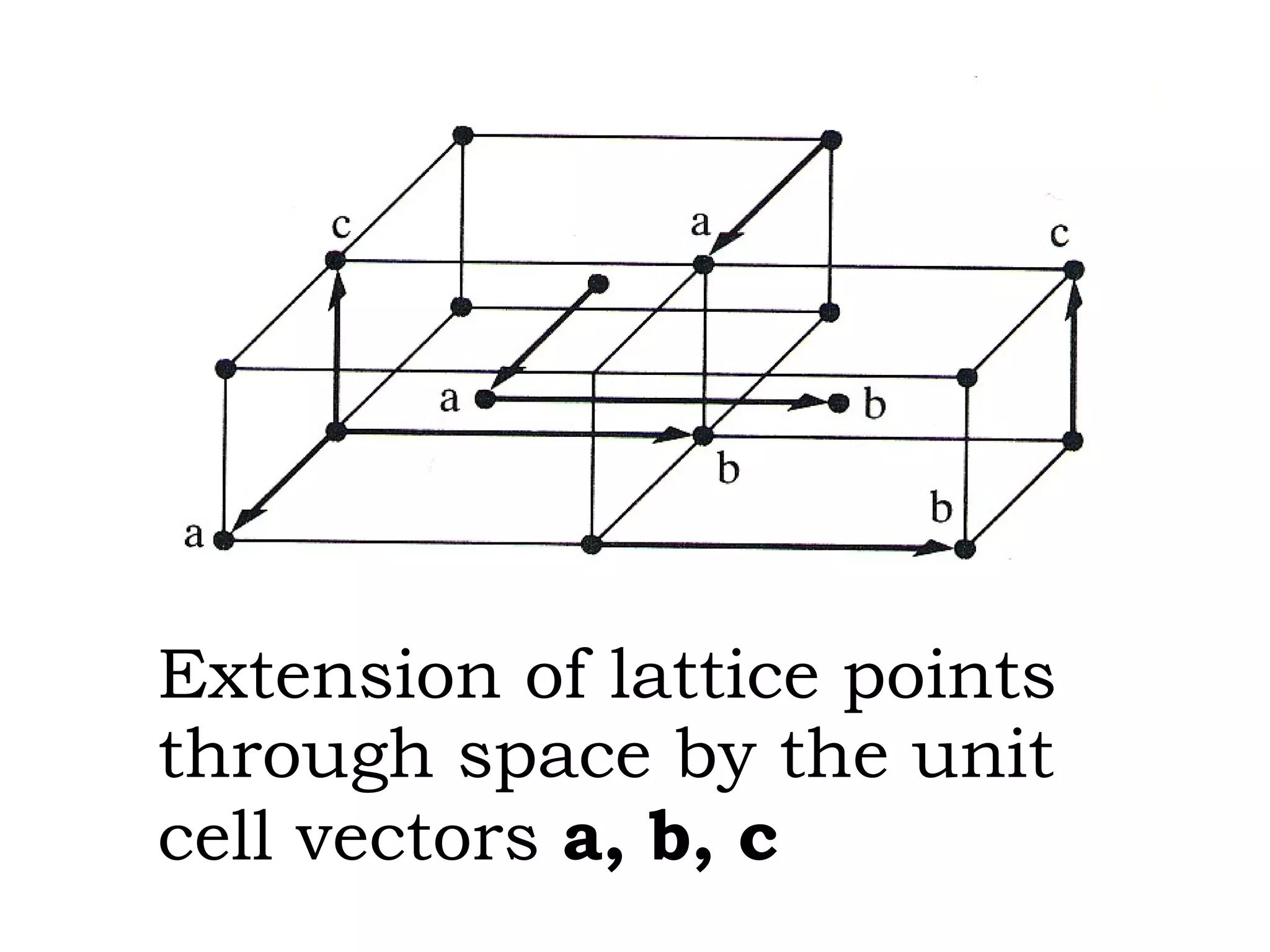
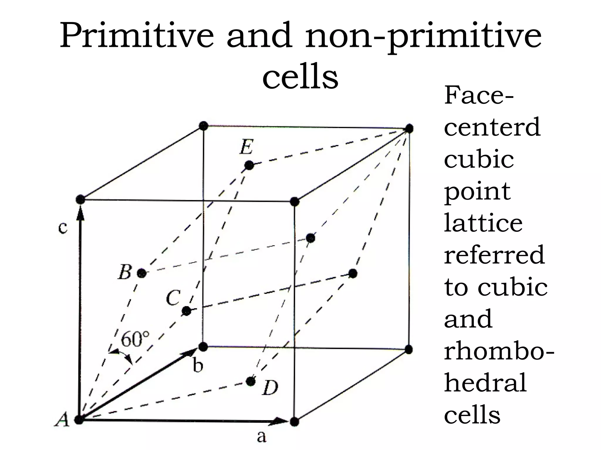
- The 14 Bravais lattices that describe the geometric arrangements of points or atoms in crystal structures.
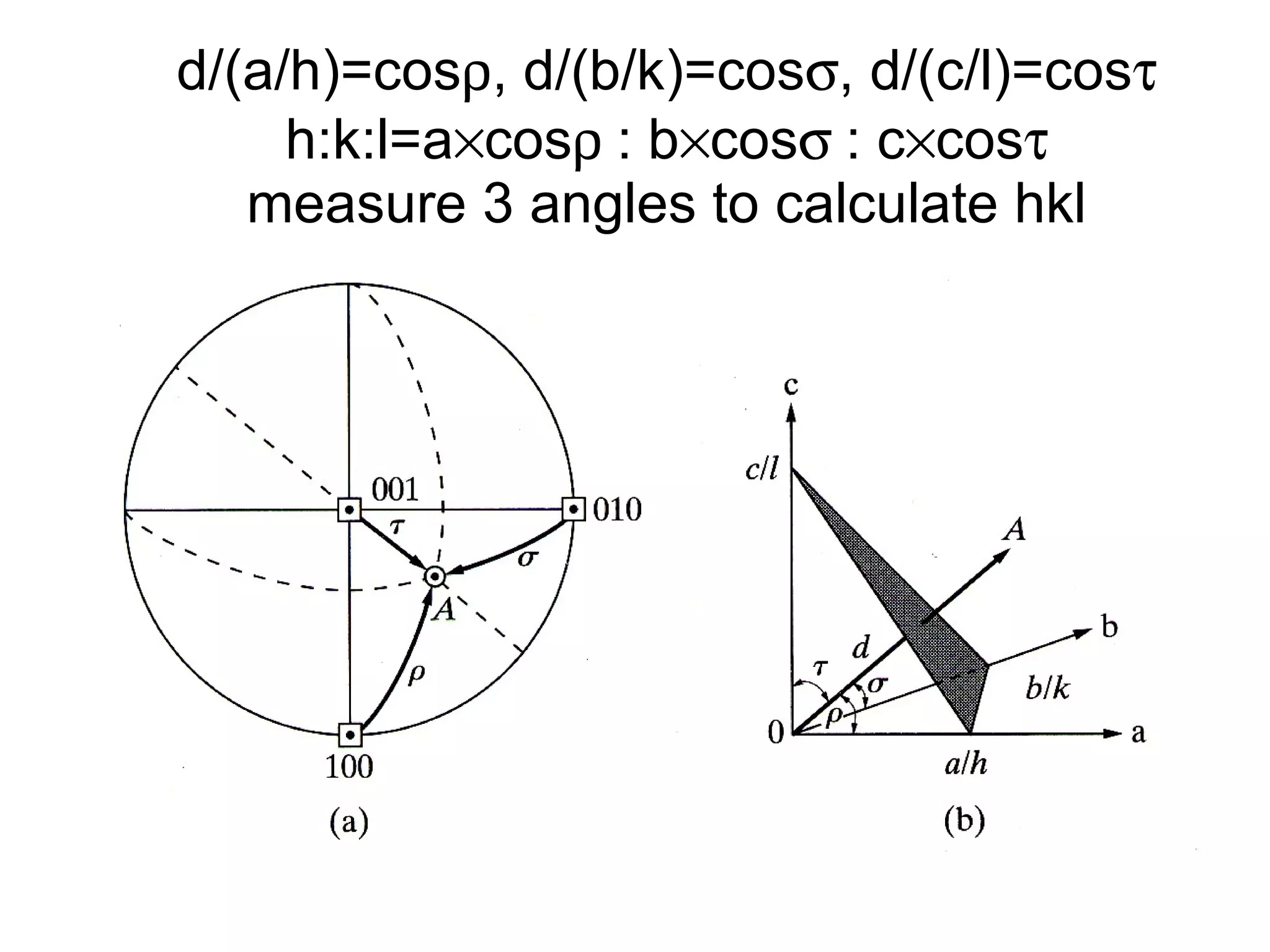
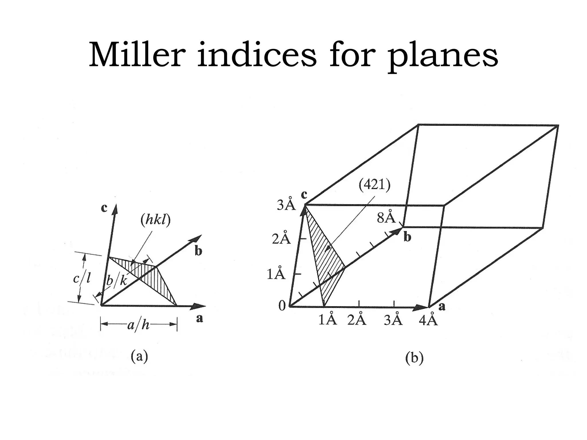
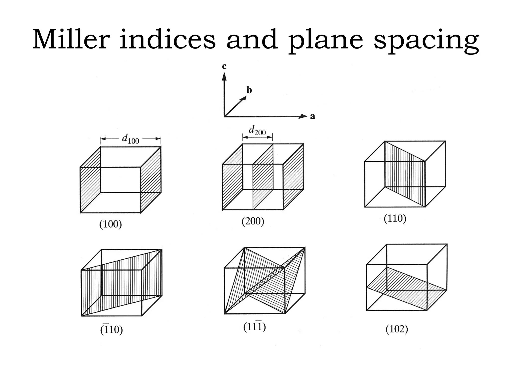
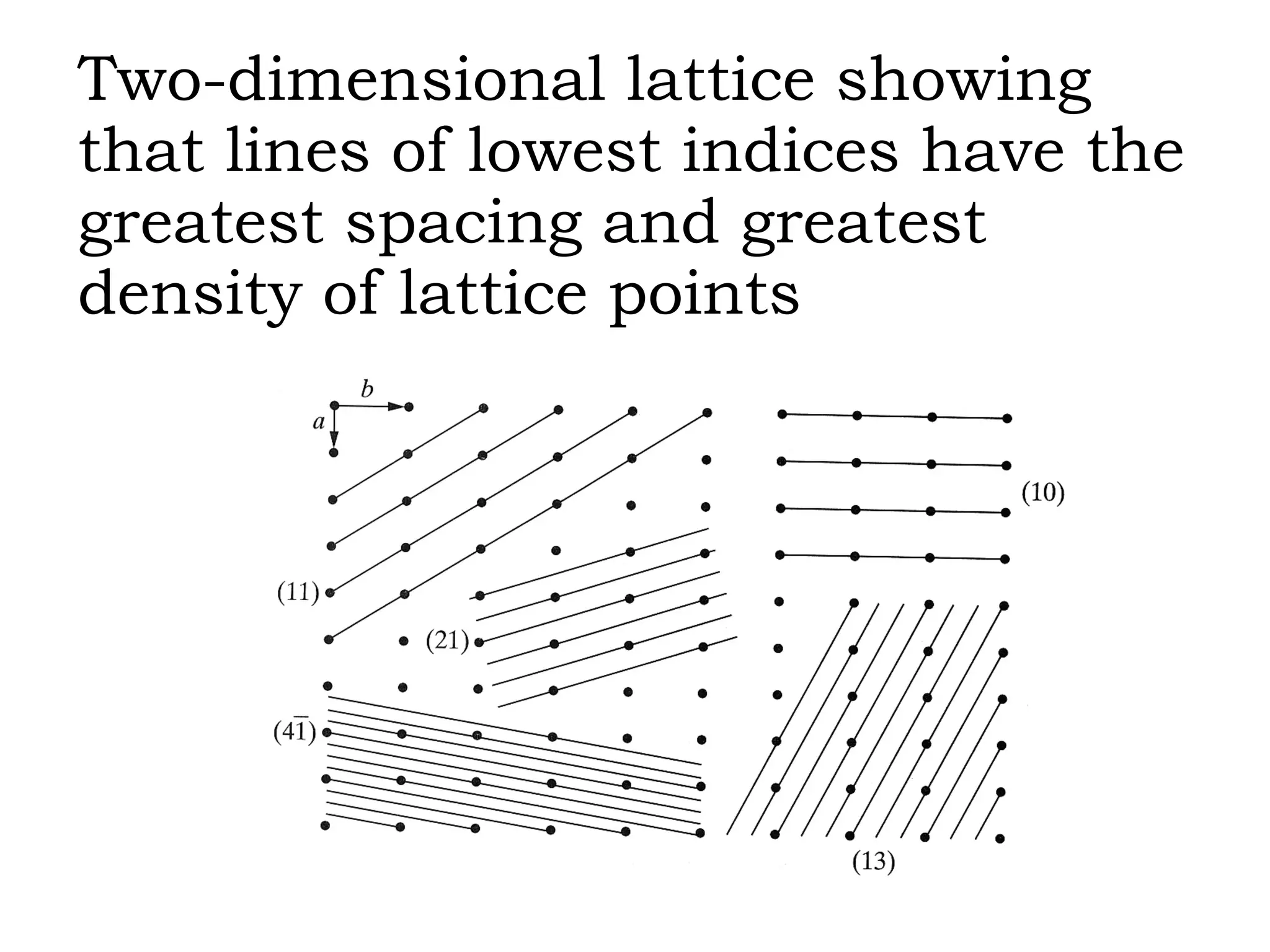
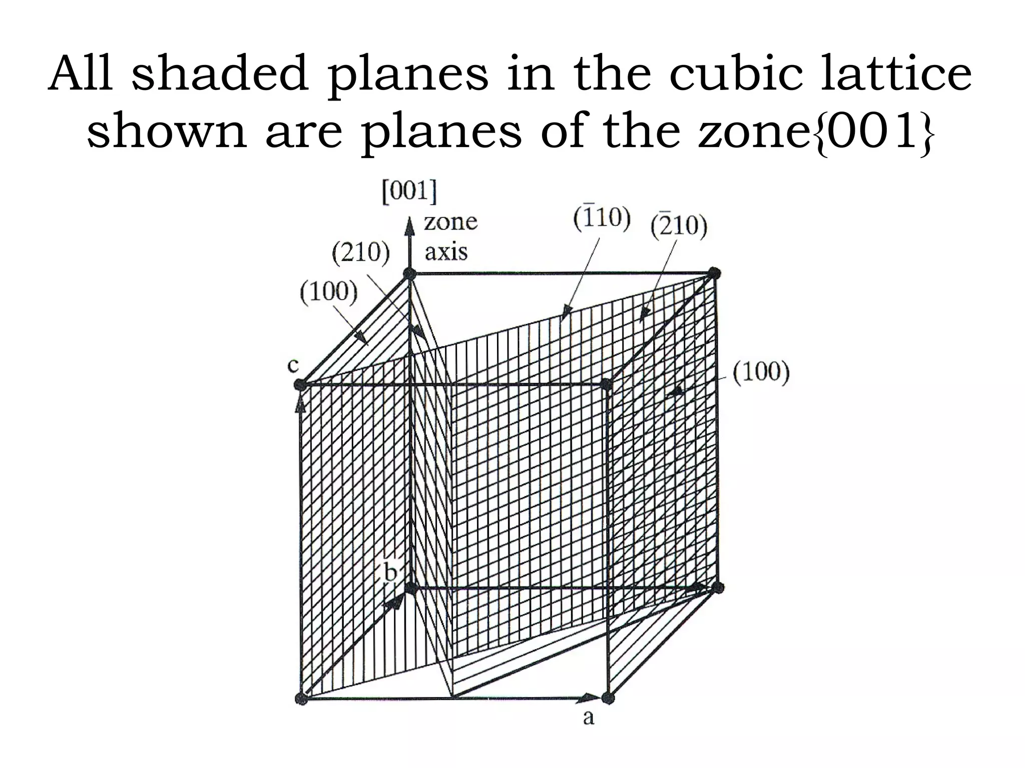
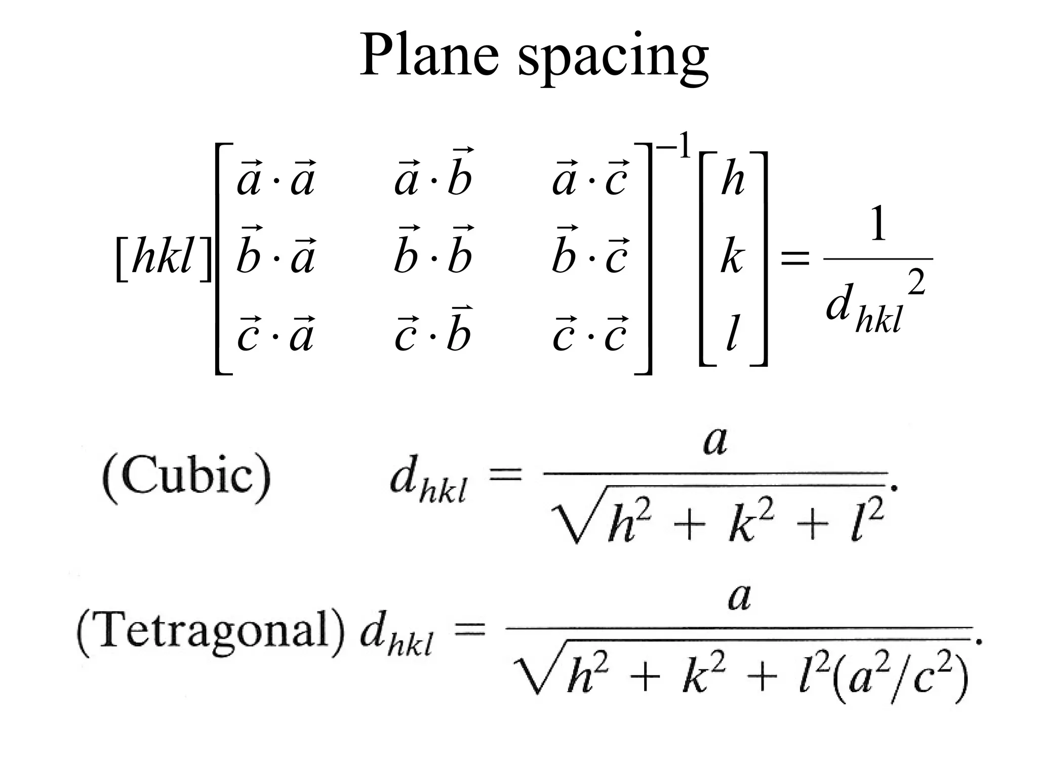
- Miller indices for describing planes in crystal structures.
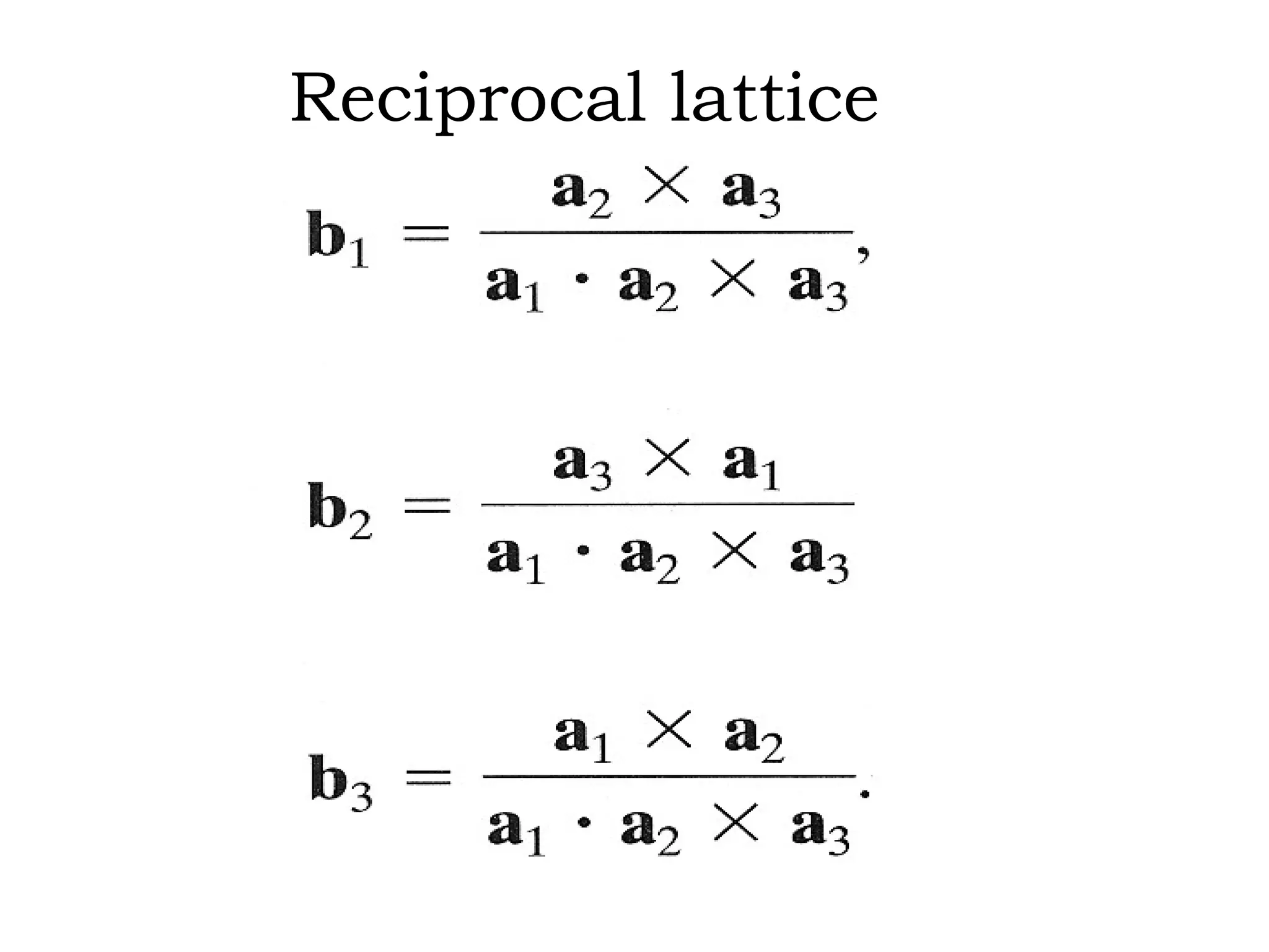
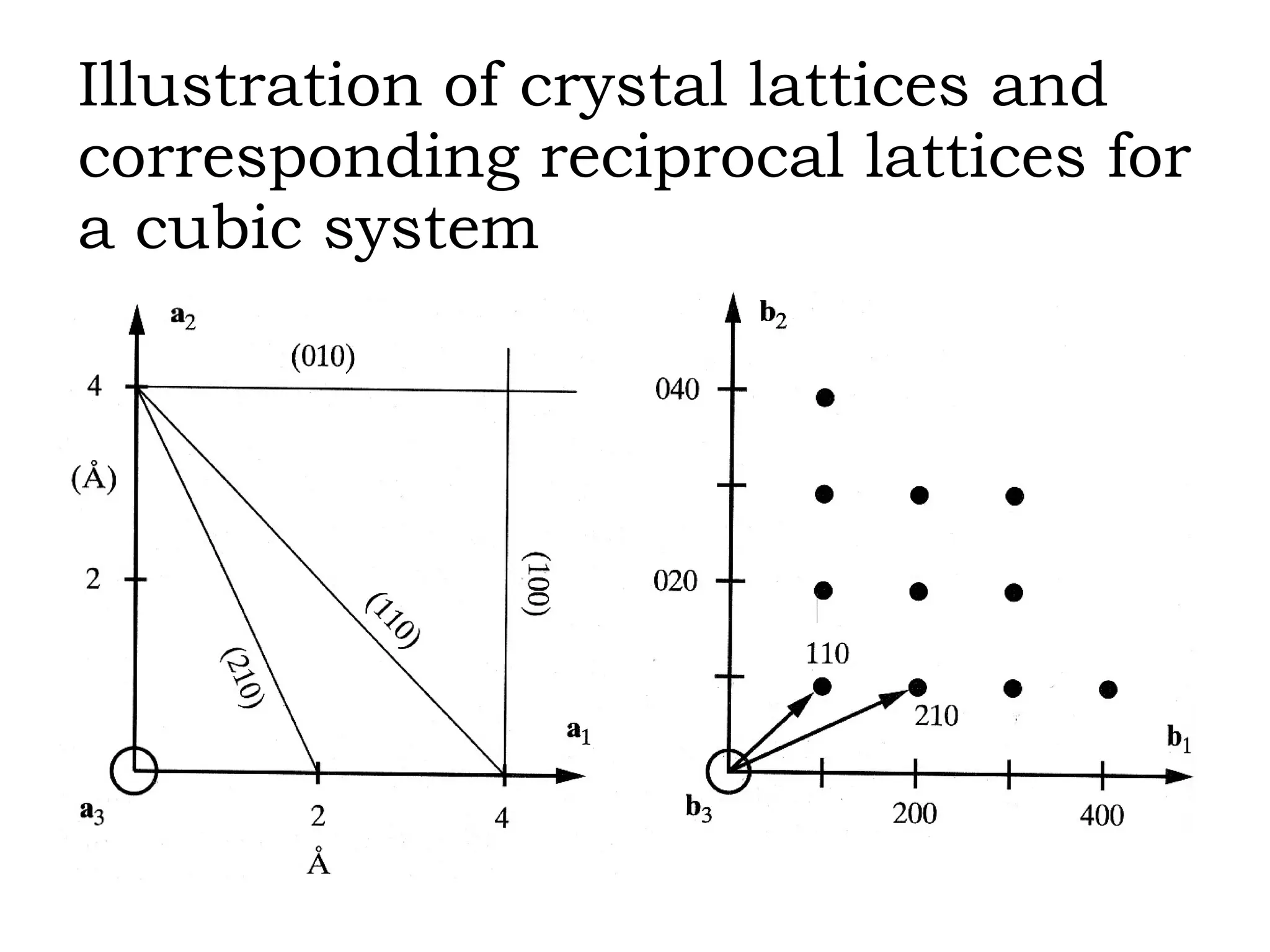
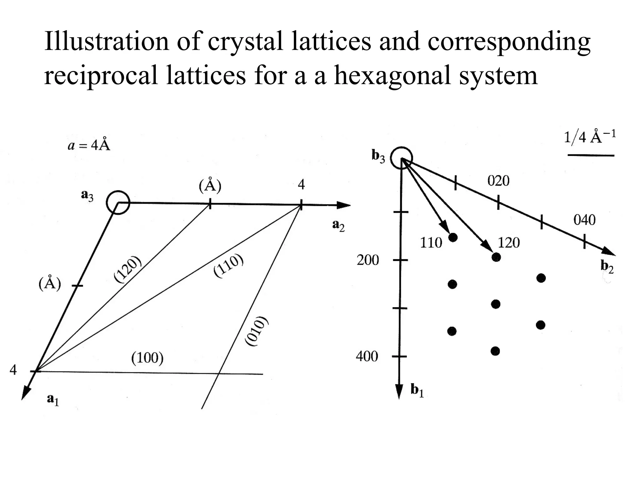
- Reciprocal lattices and how they relate to direct crystal lattices.
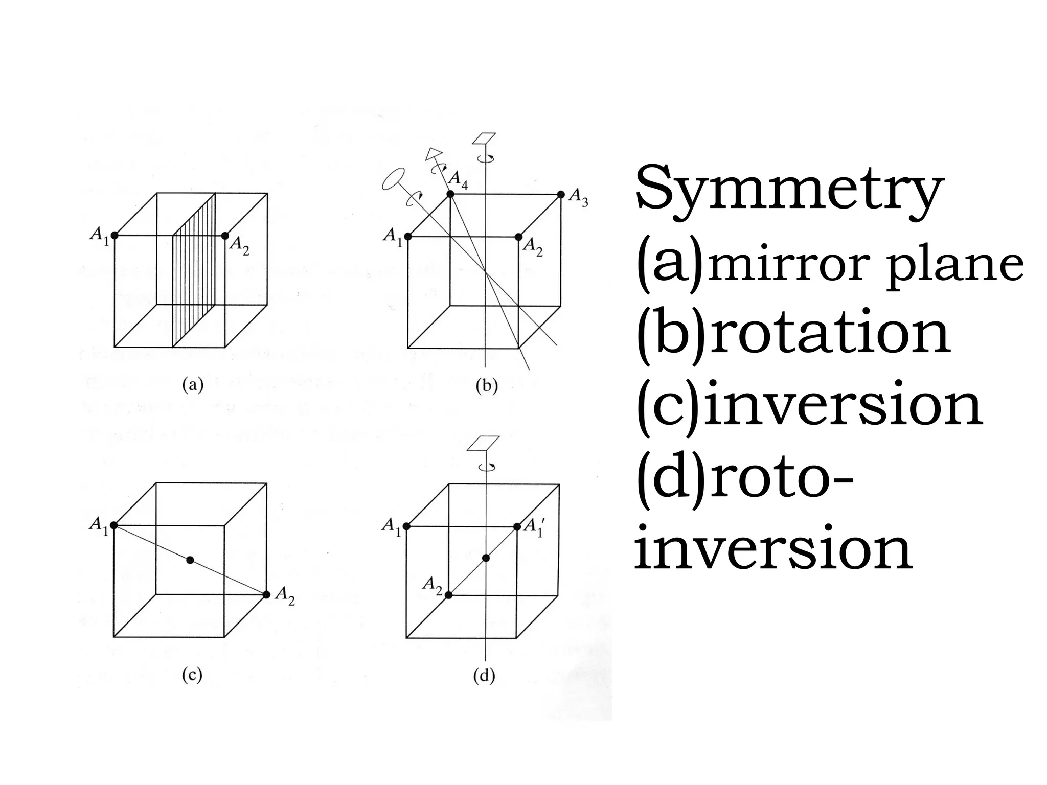
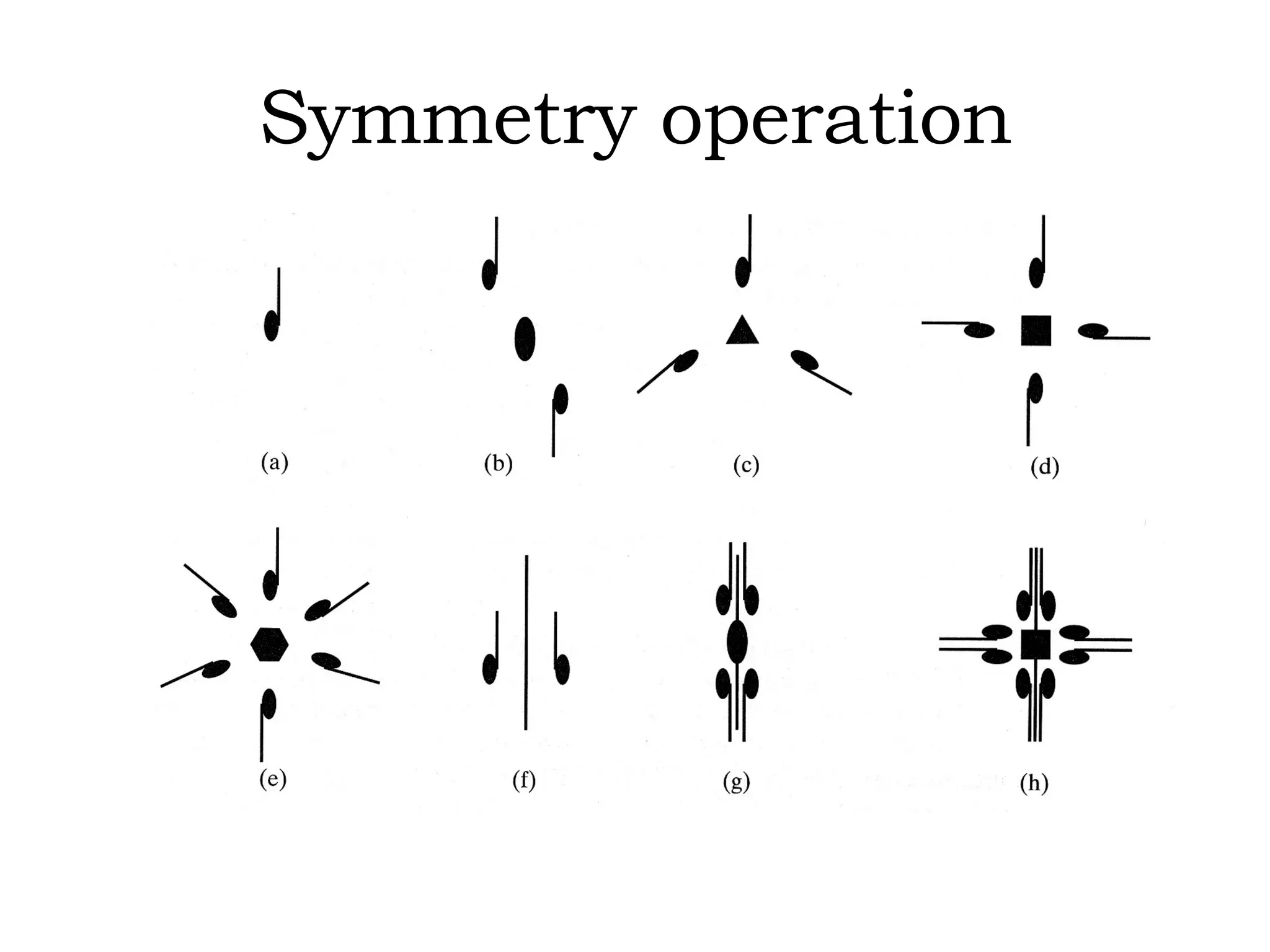
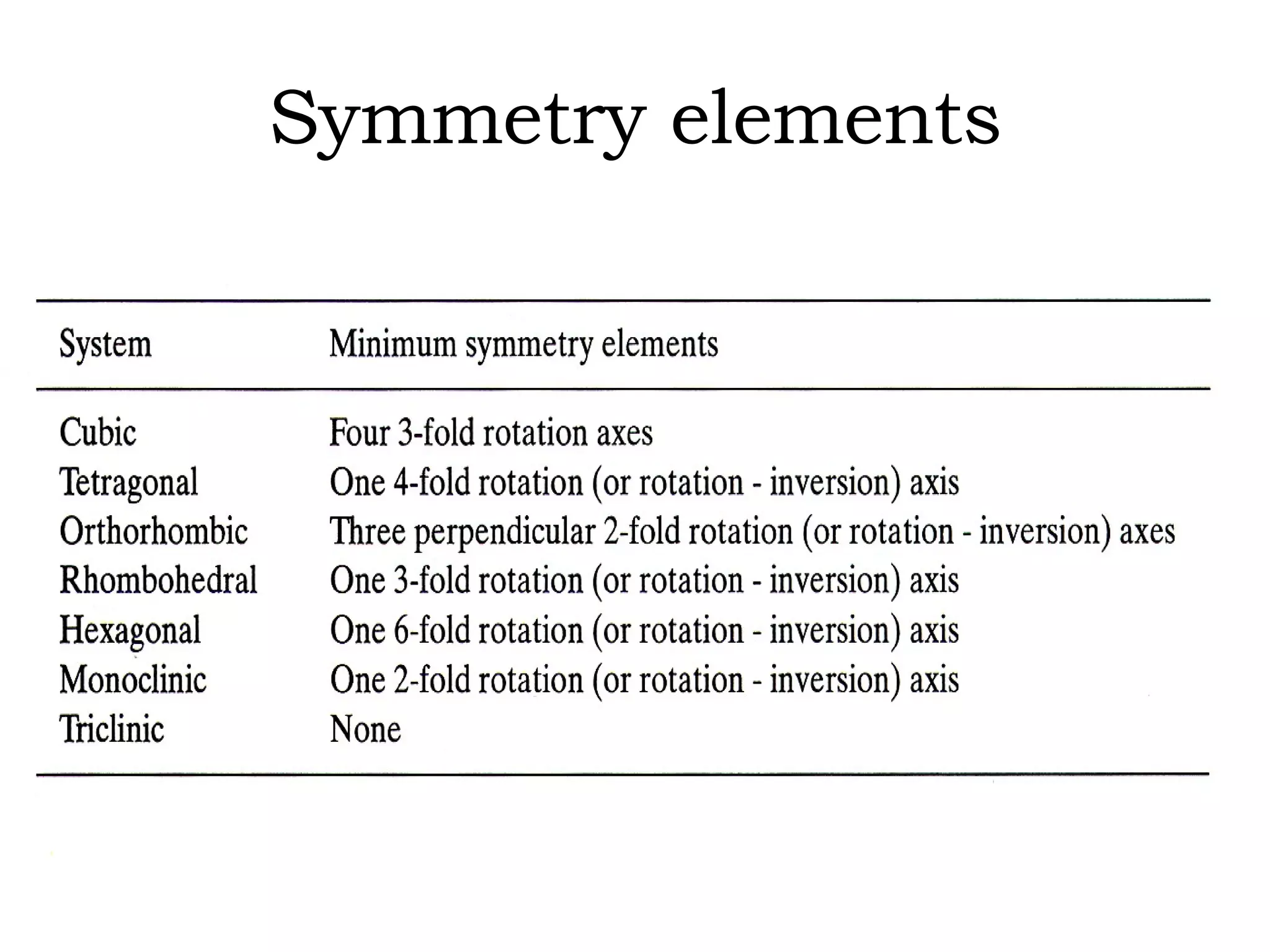
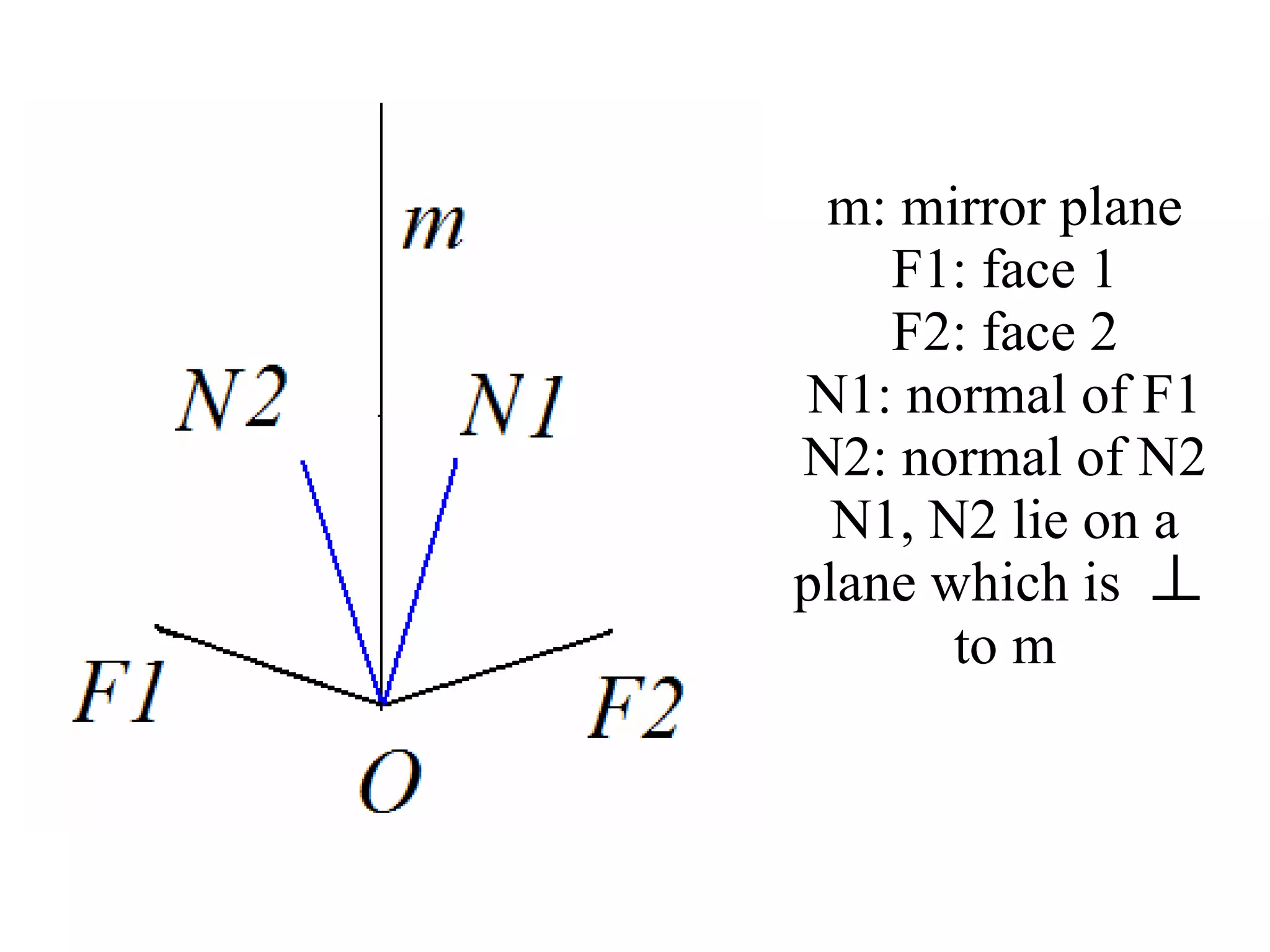
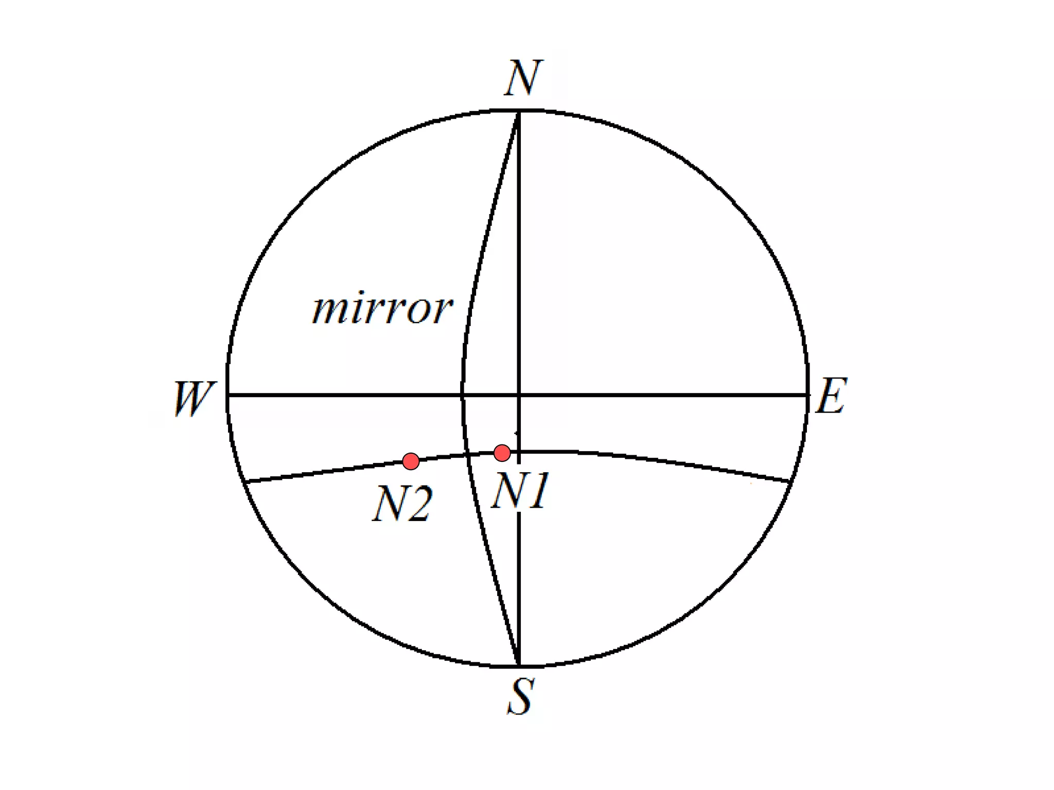
- Symmetry operations and elements that are present in different crystal systems.
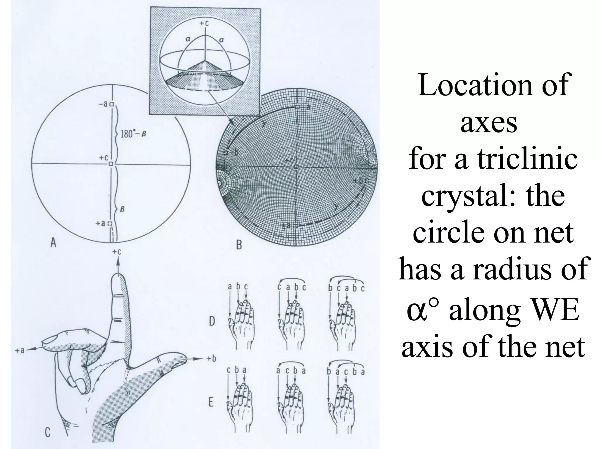
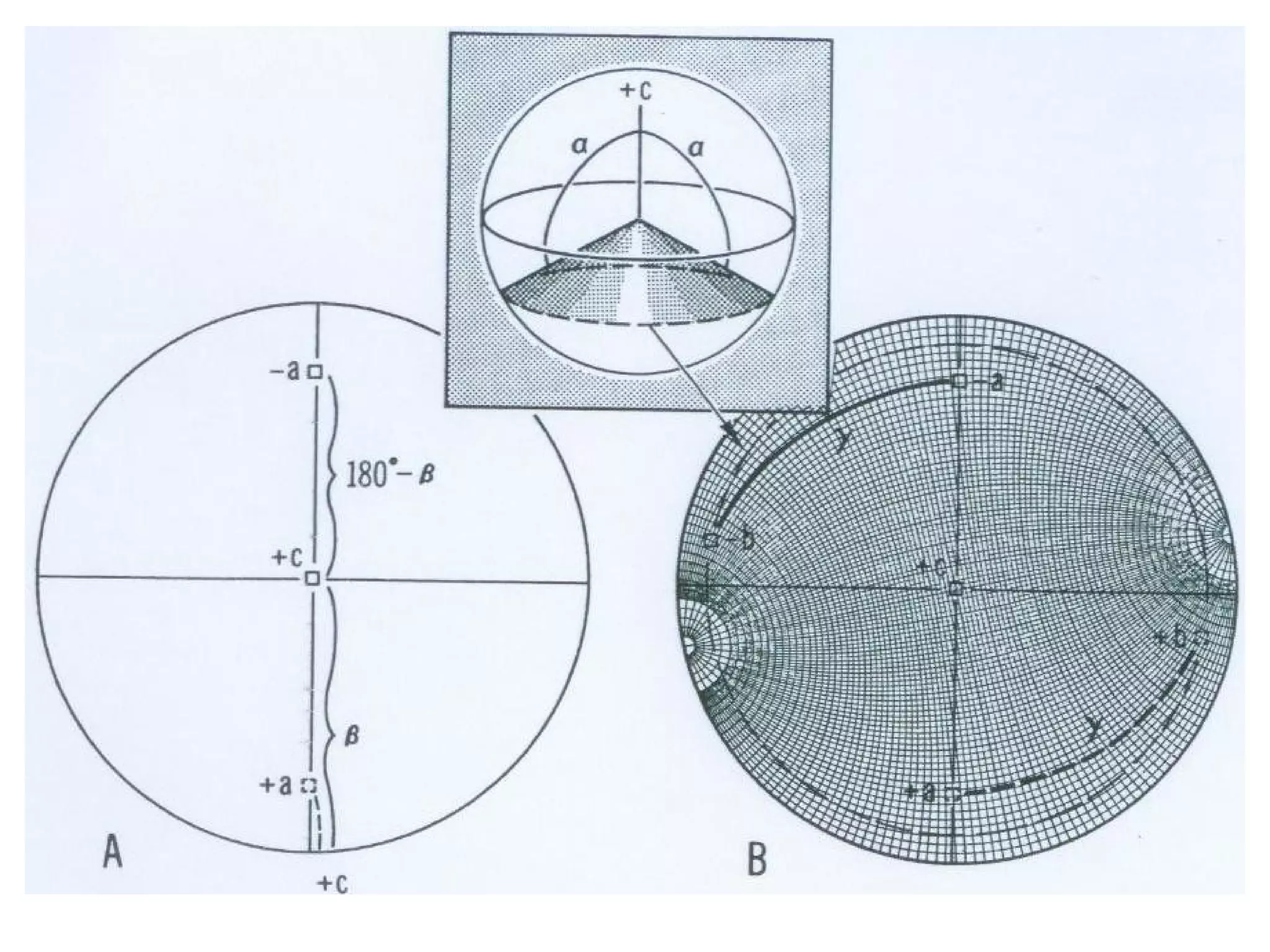
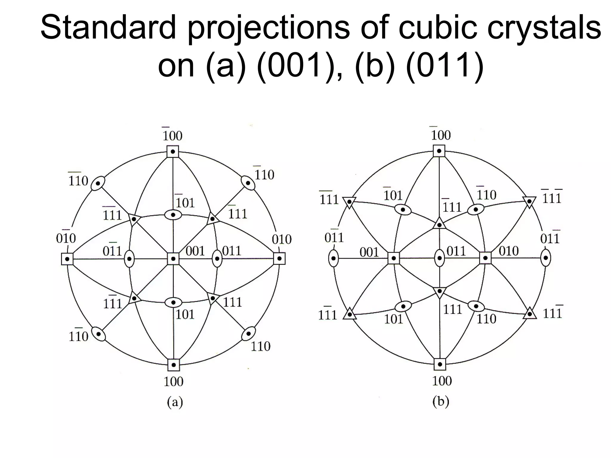
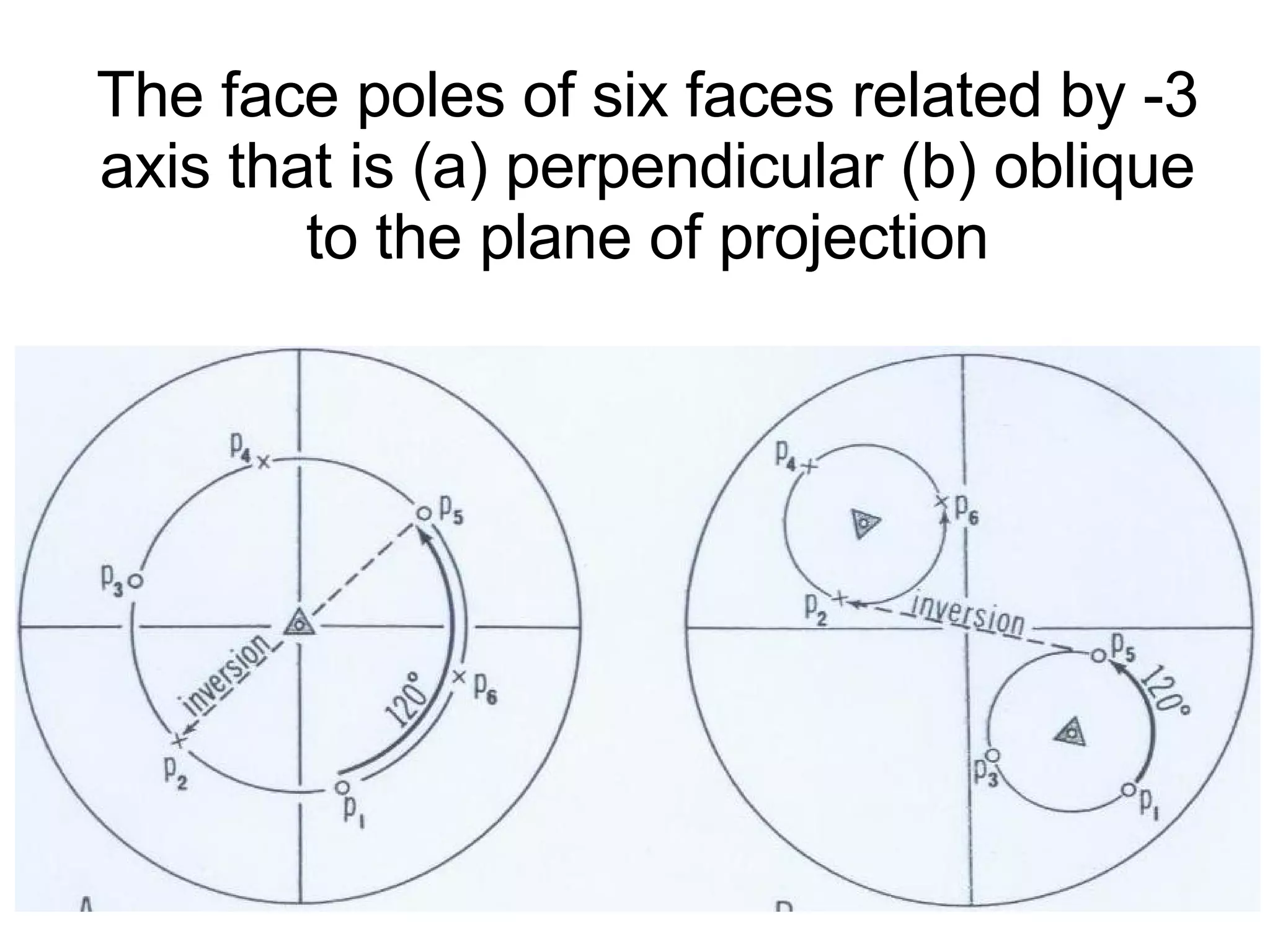
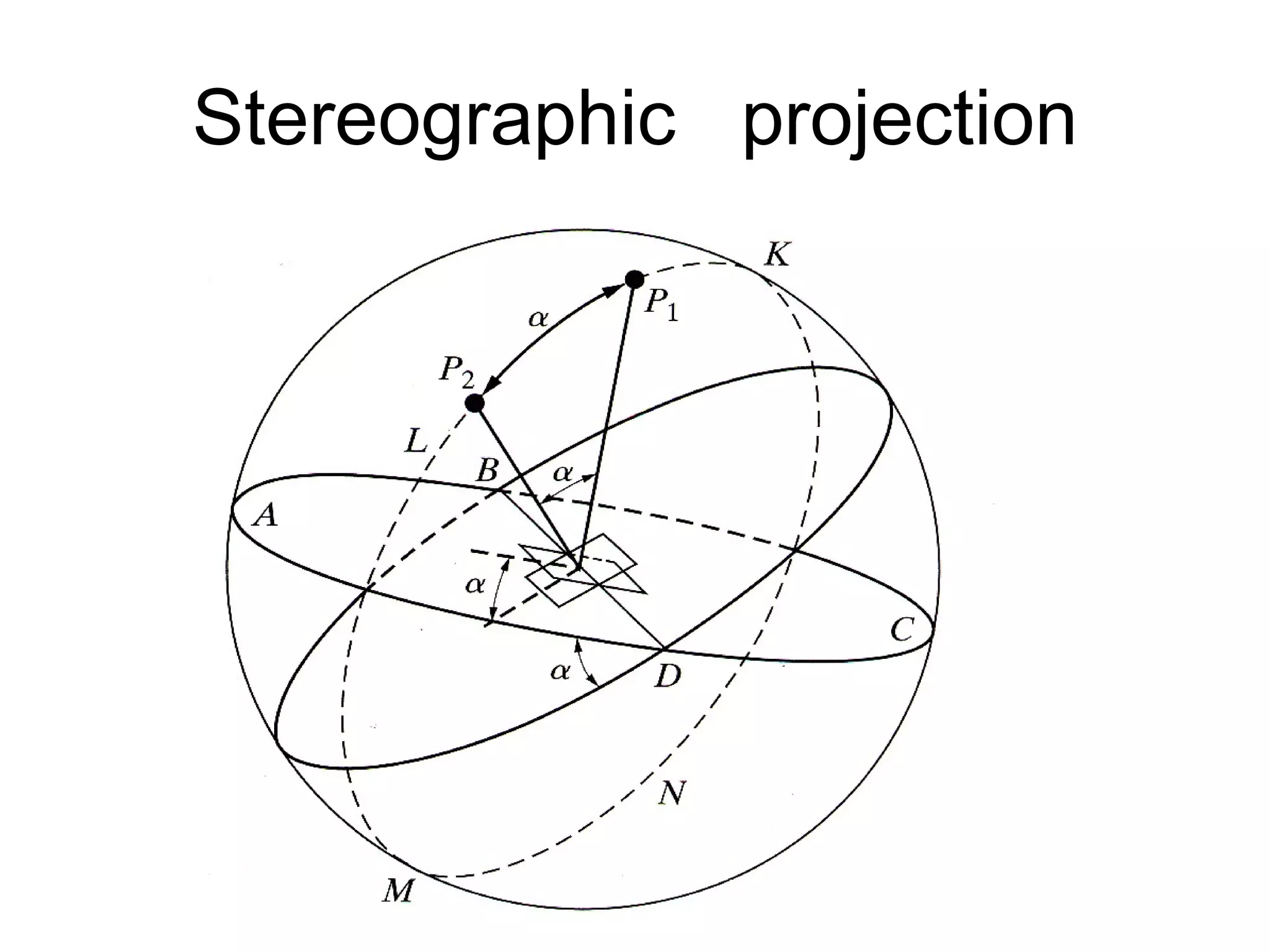
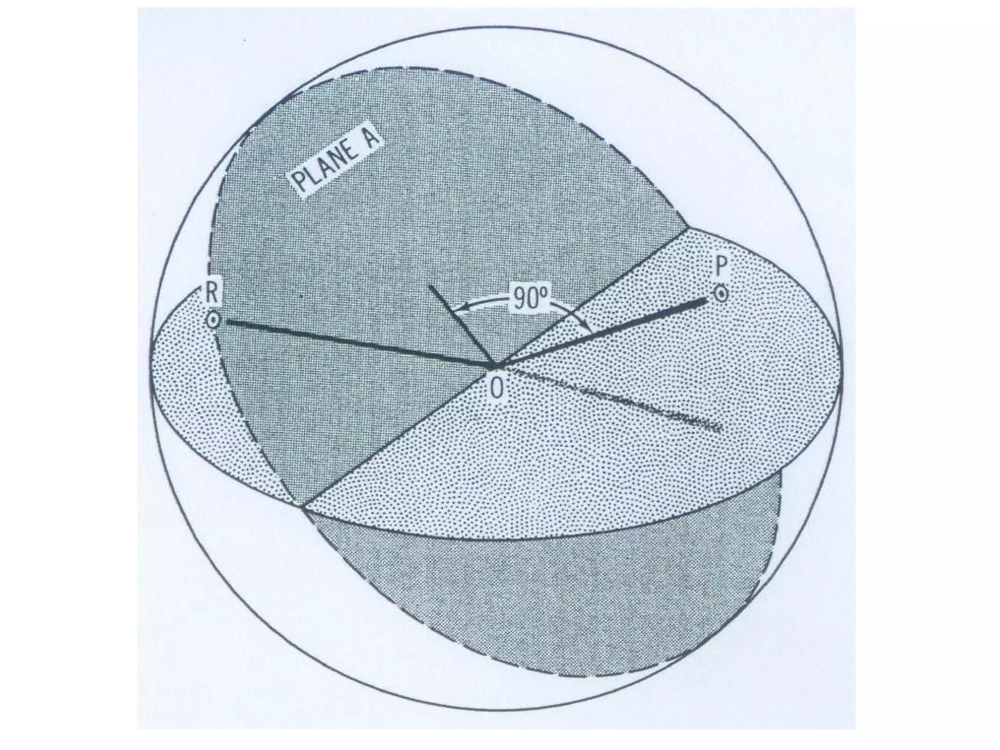
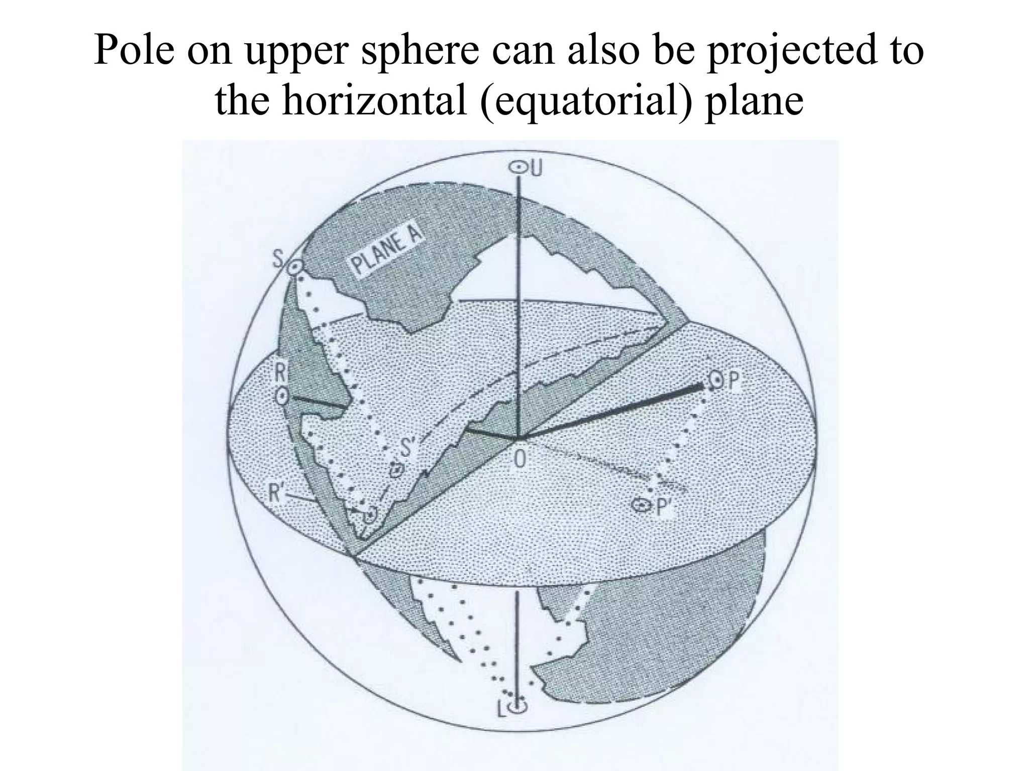
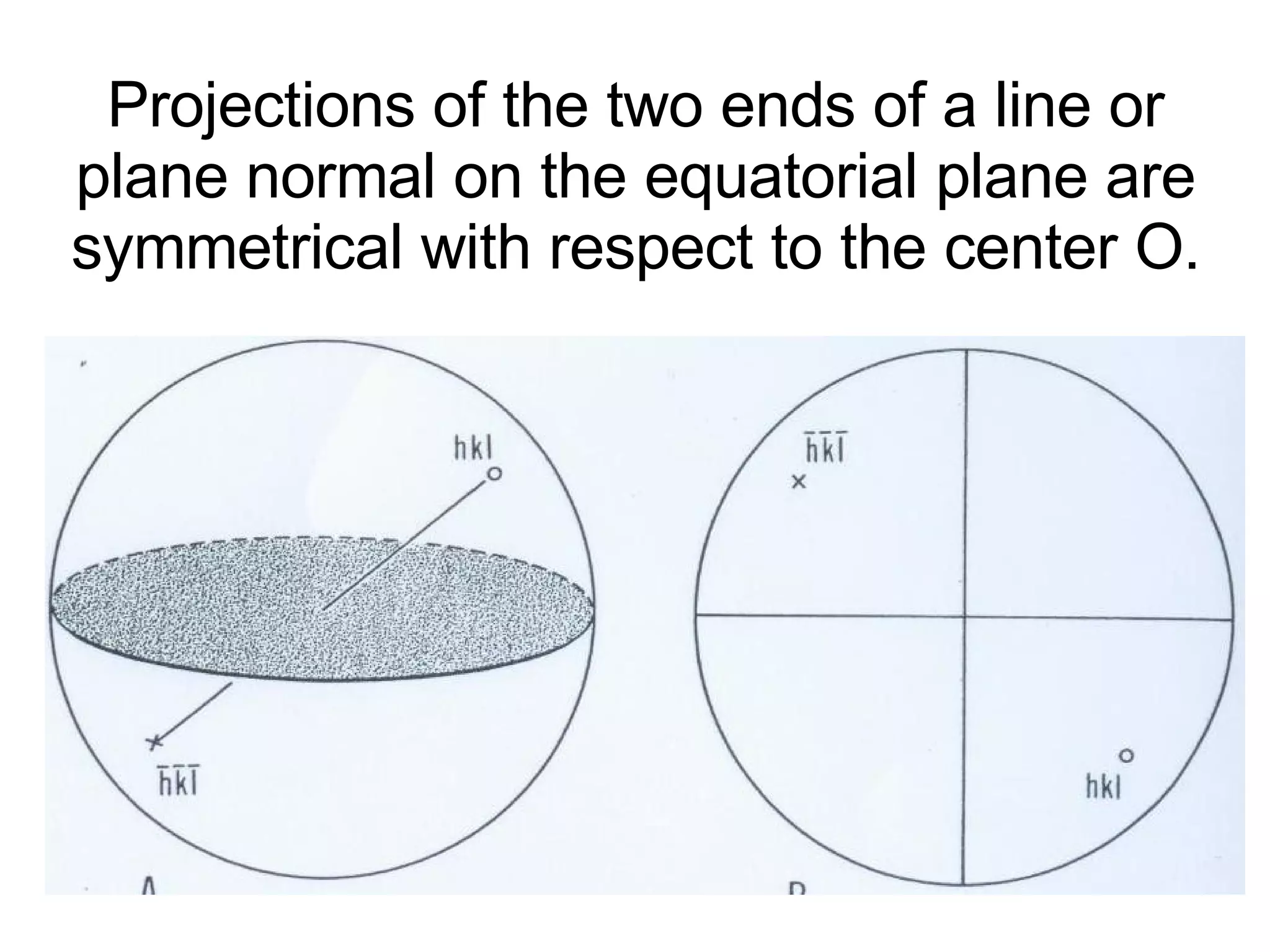
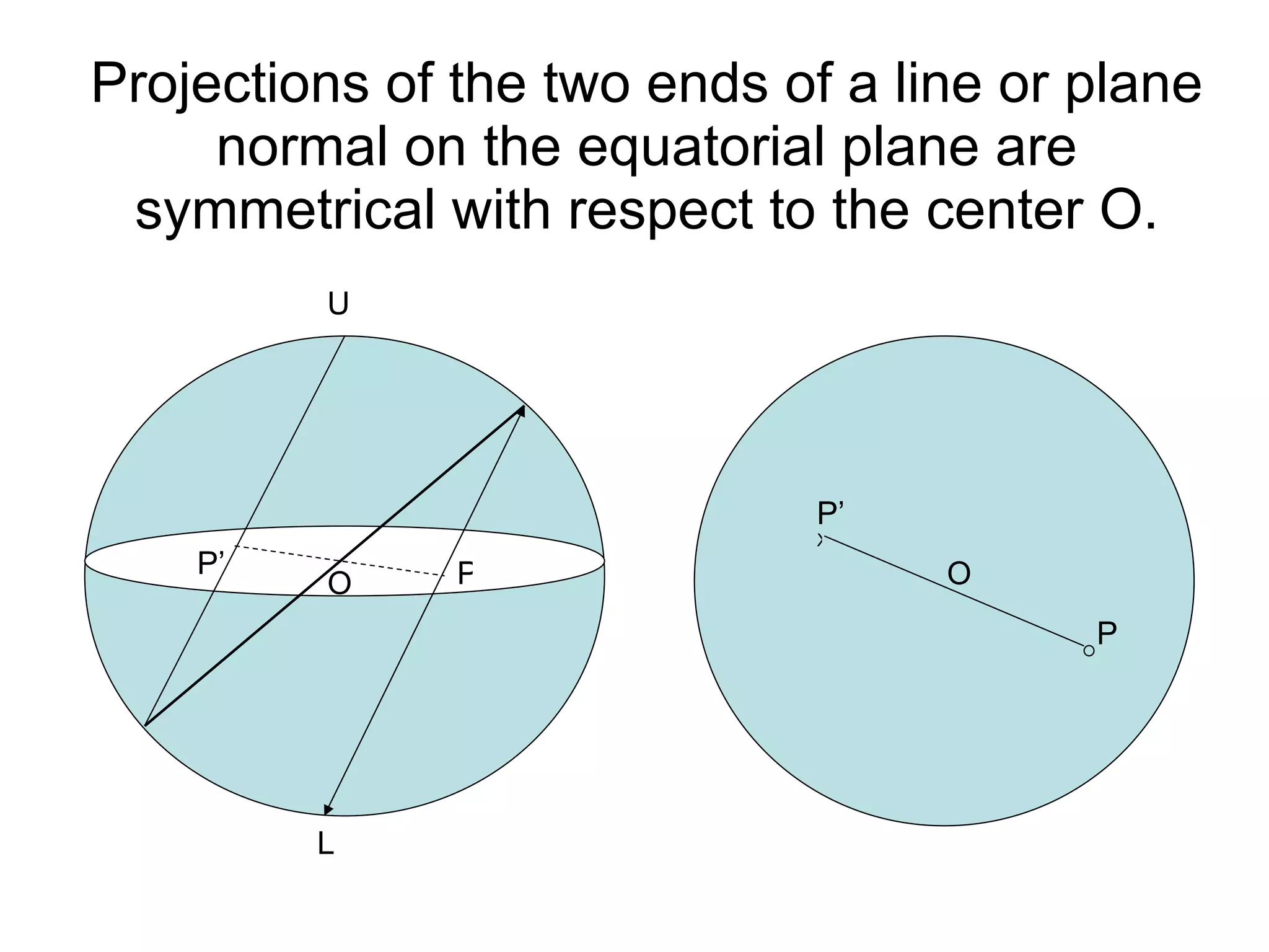
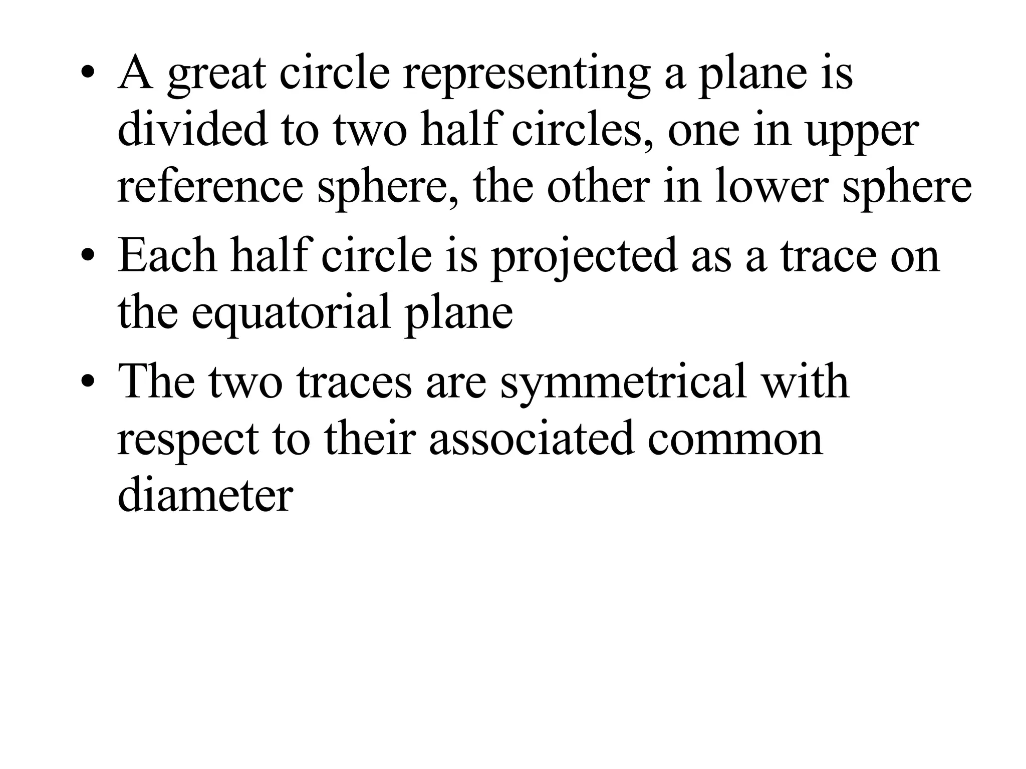
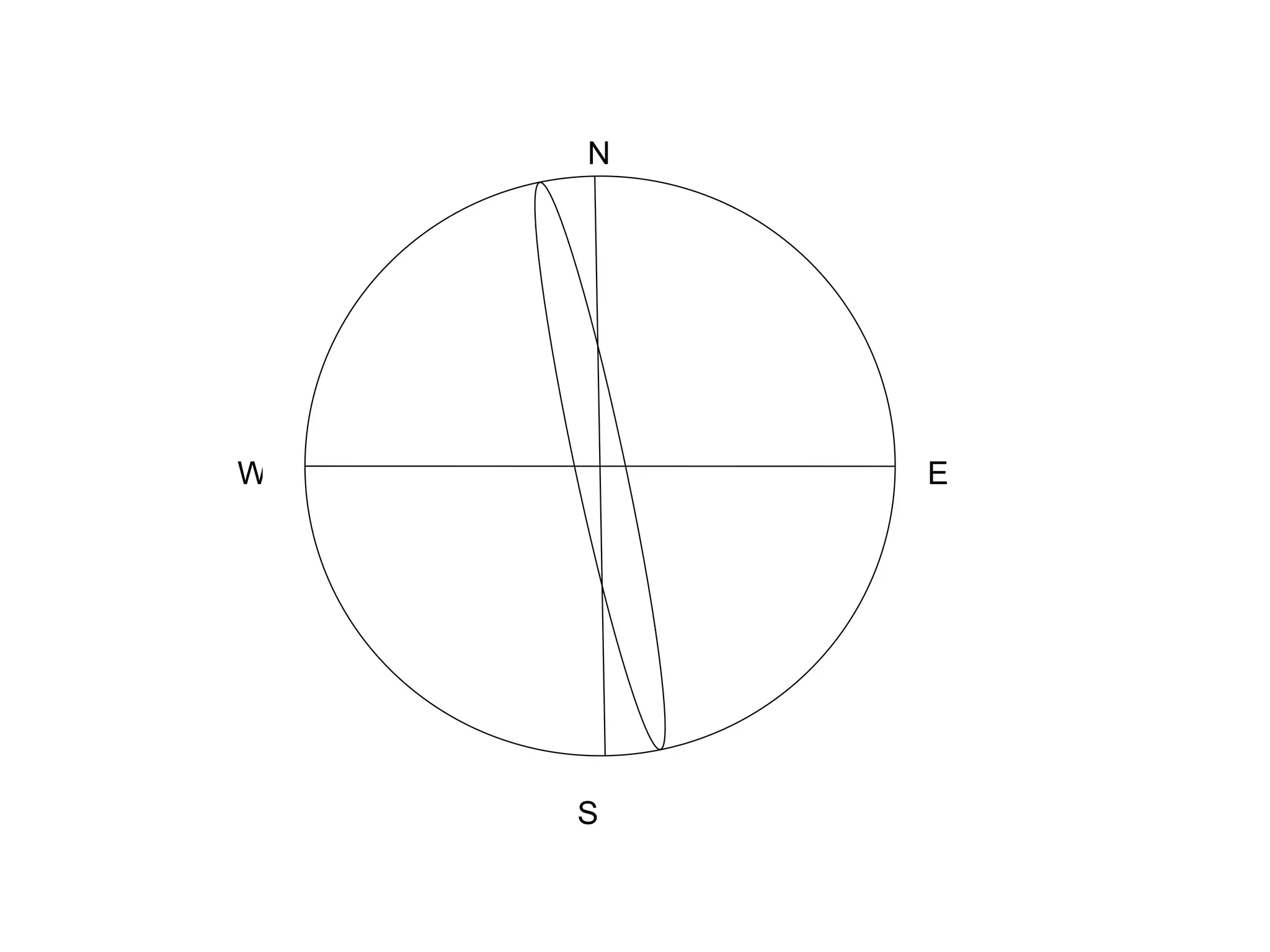
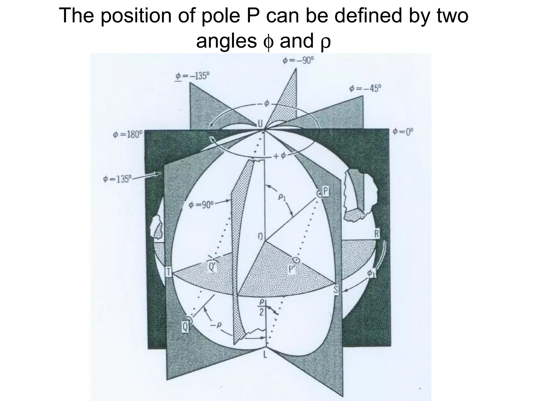
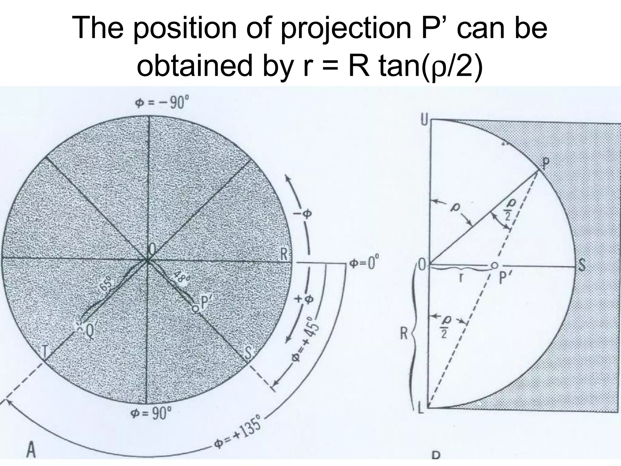
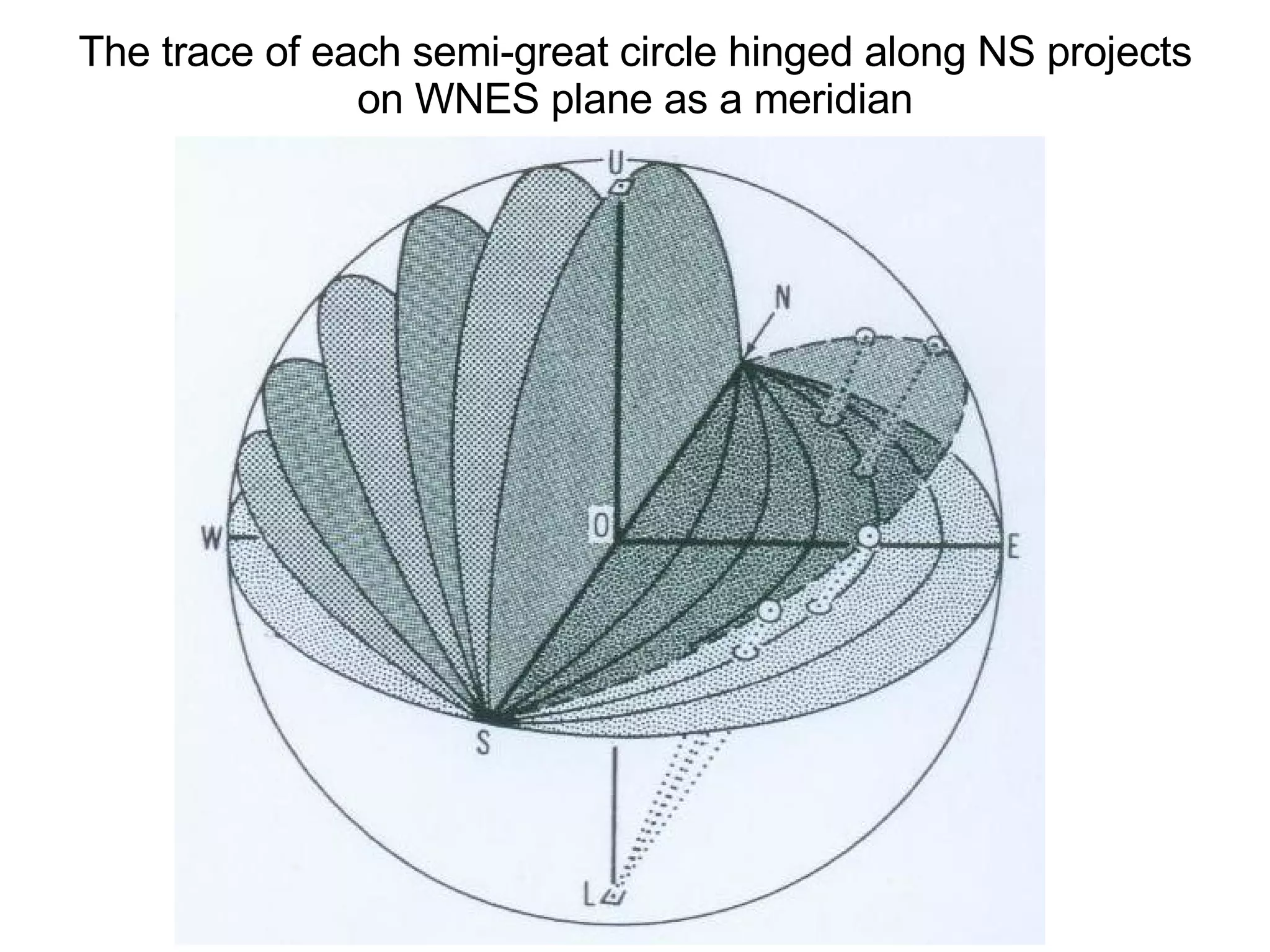
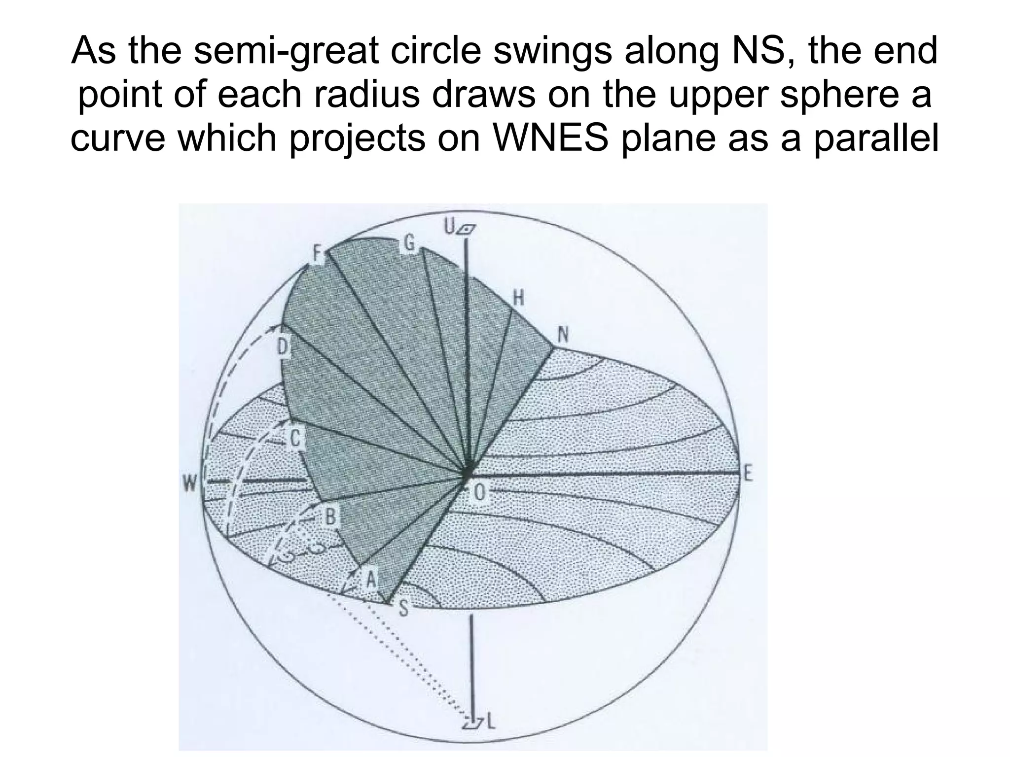
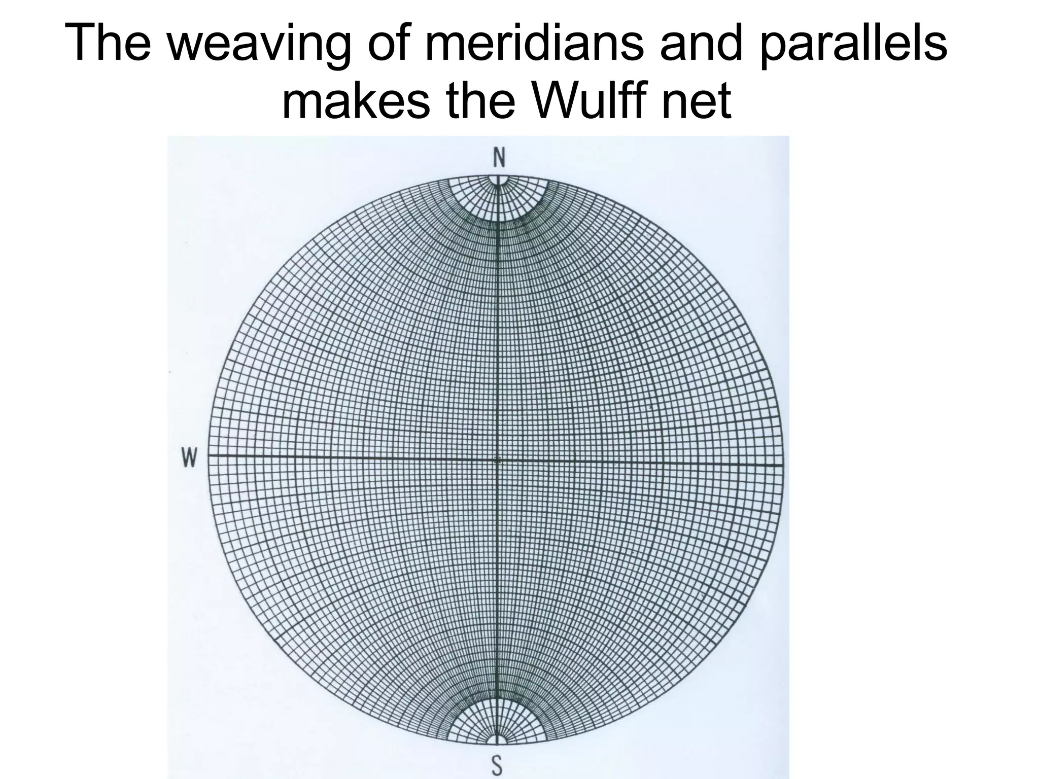
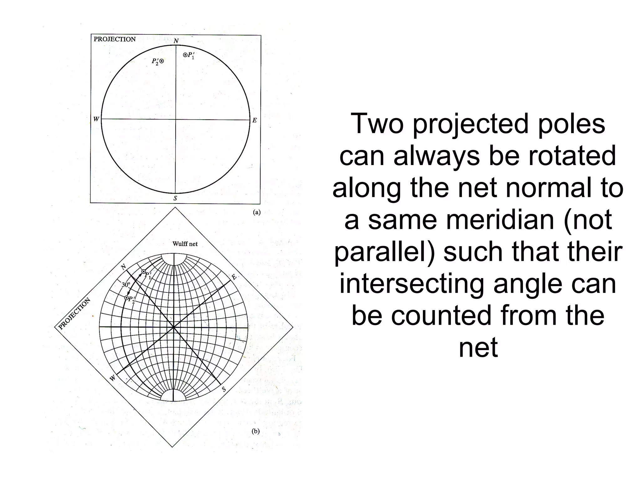
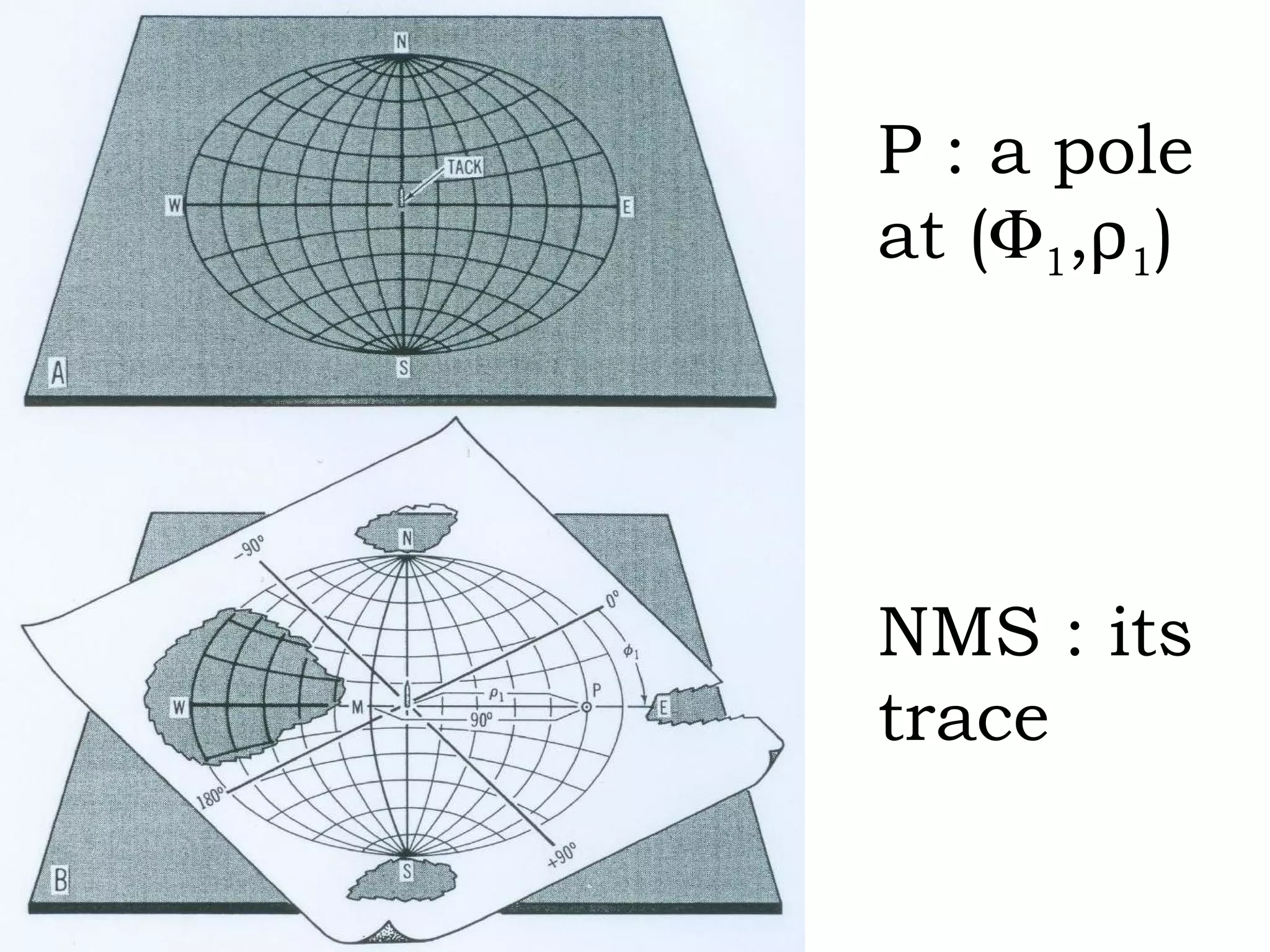
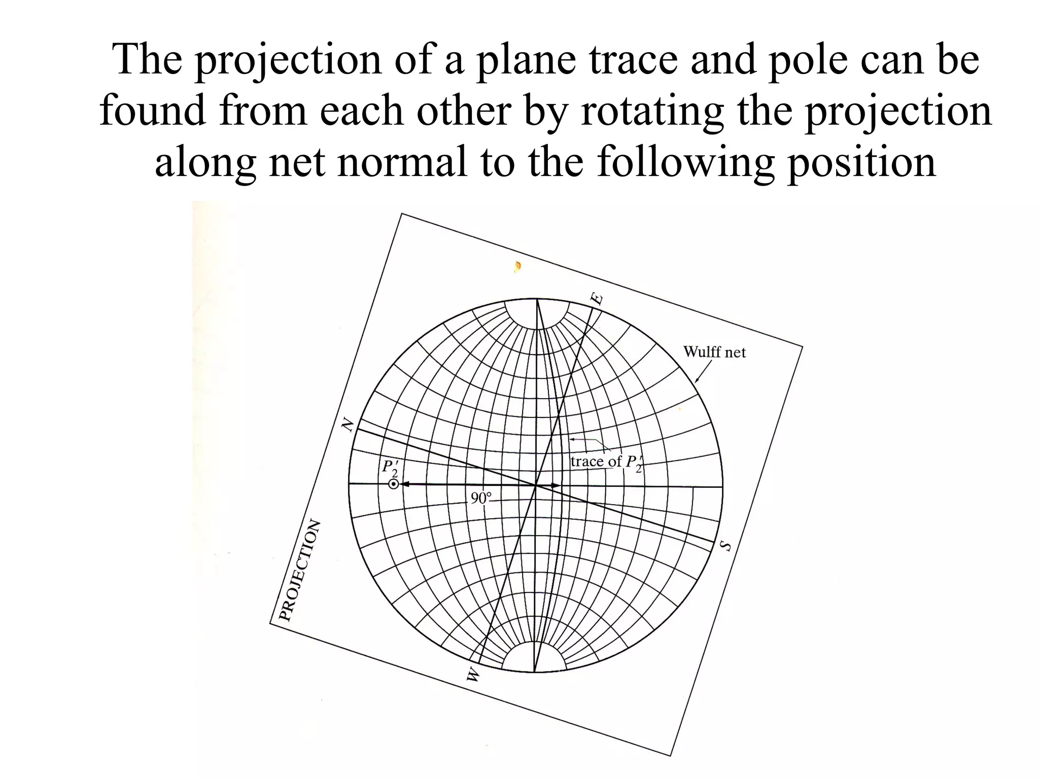
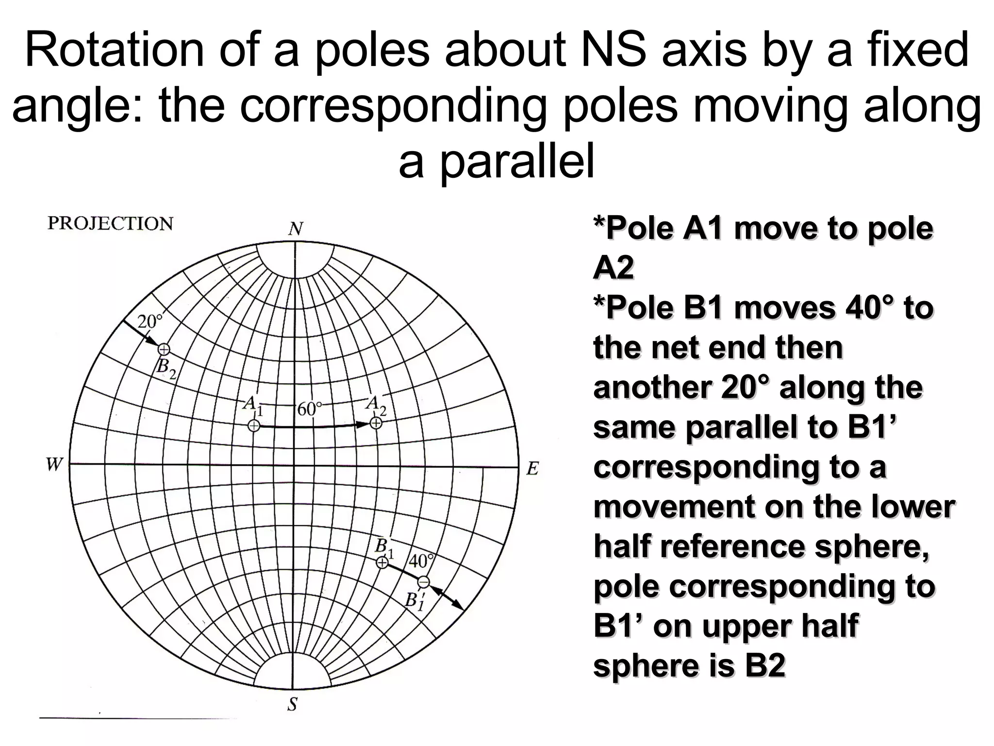
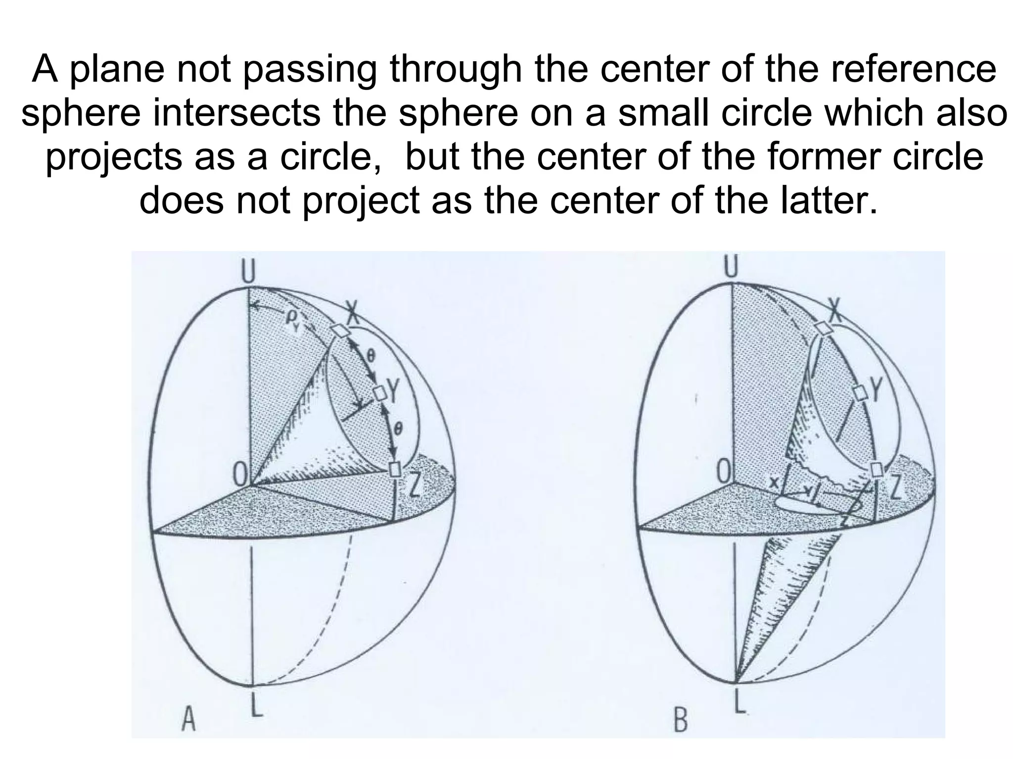
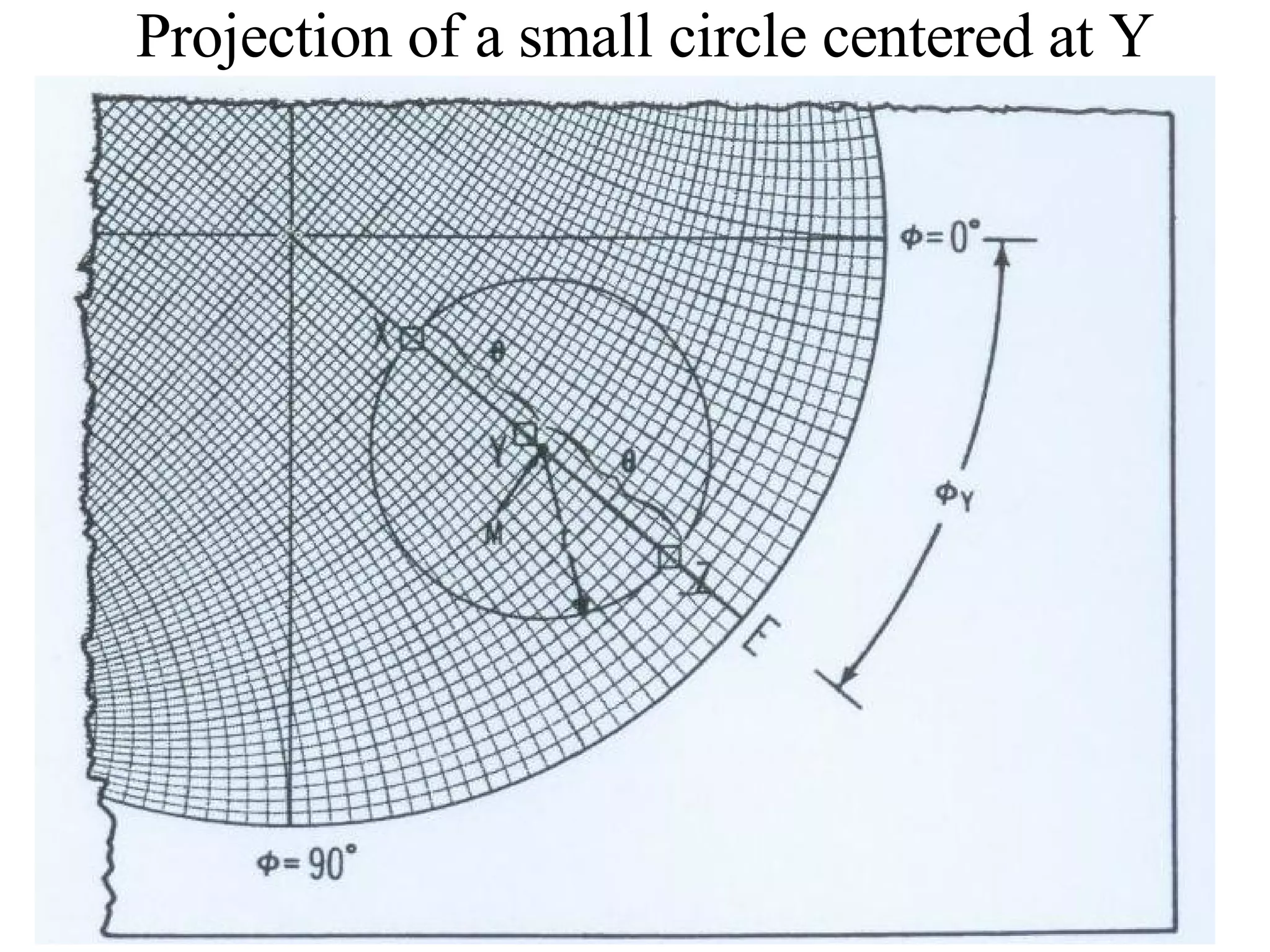
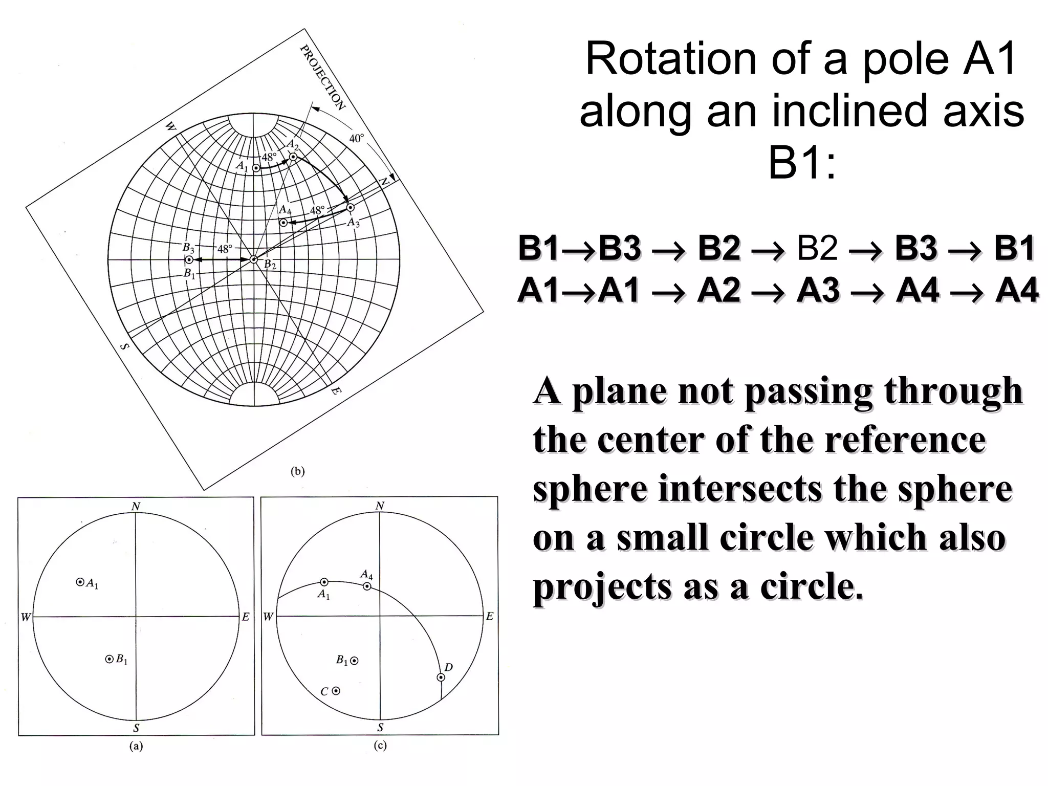
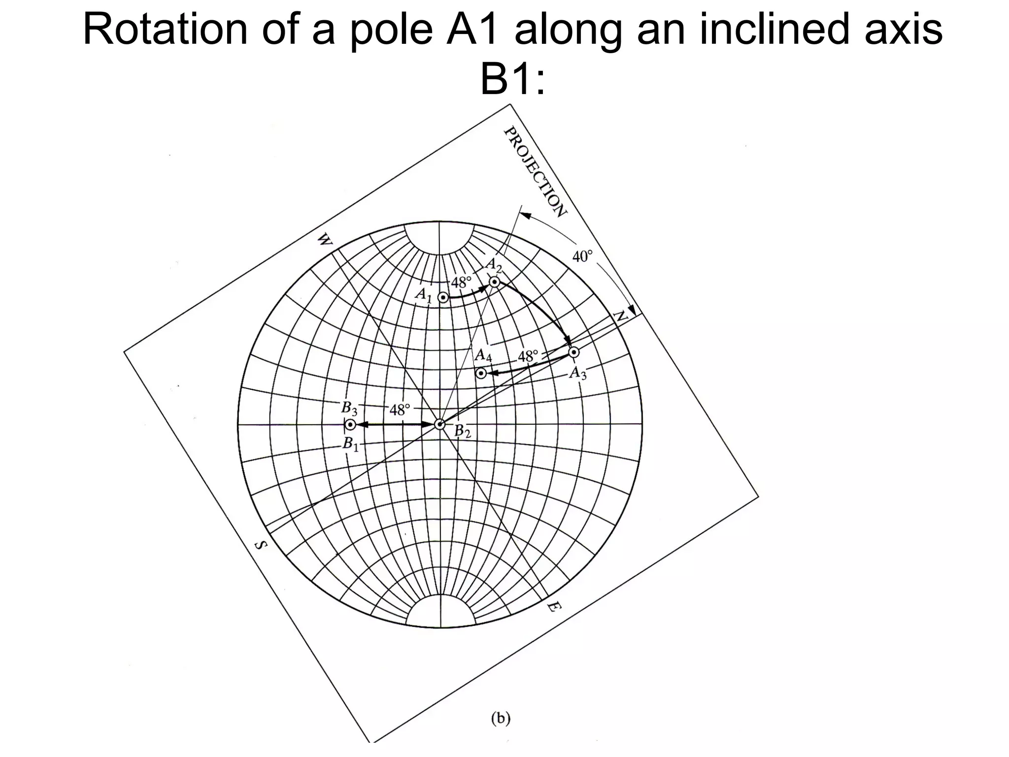
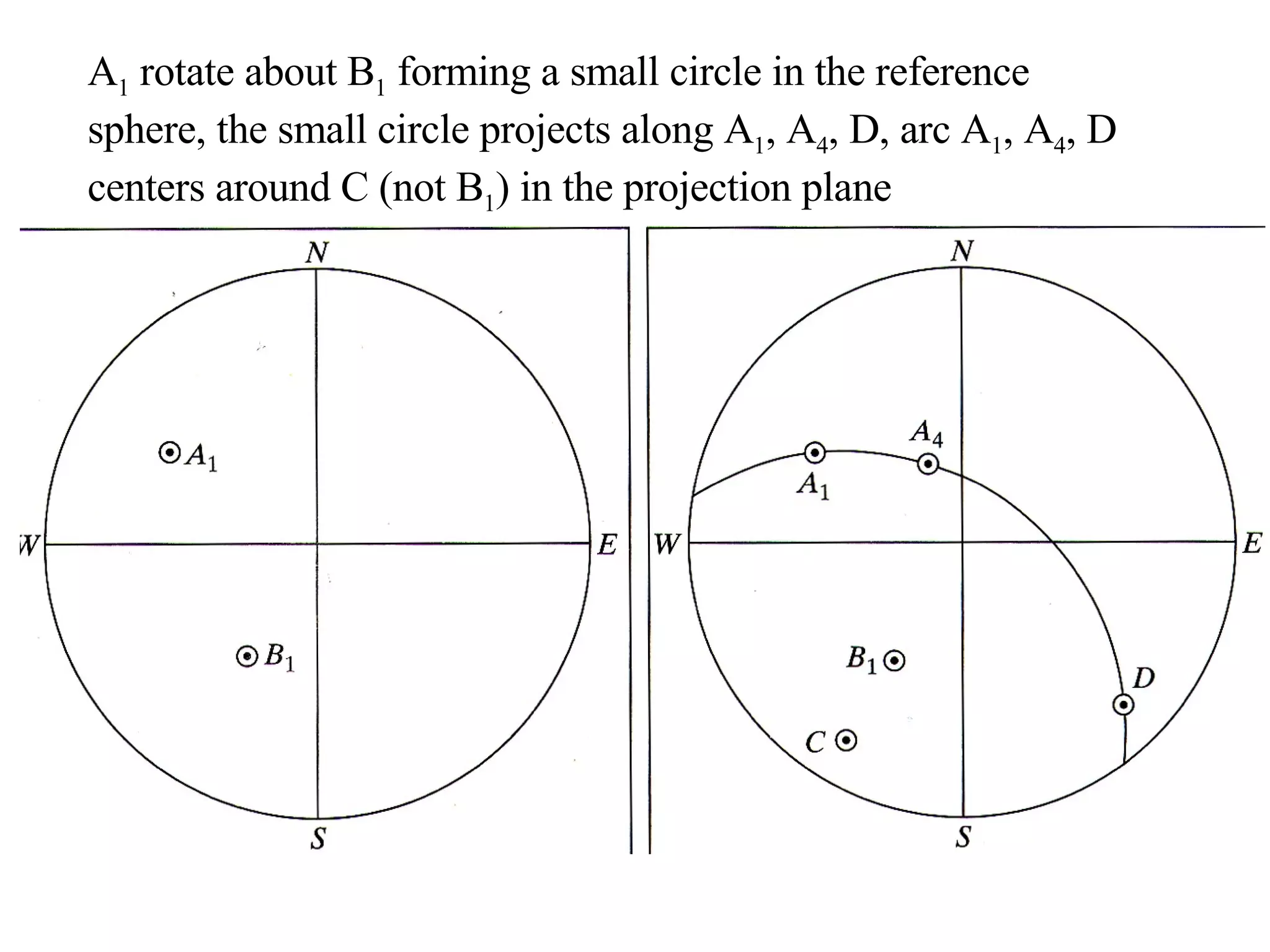
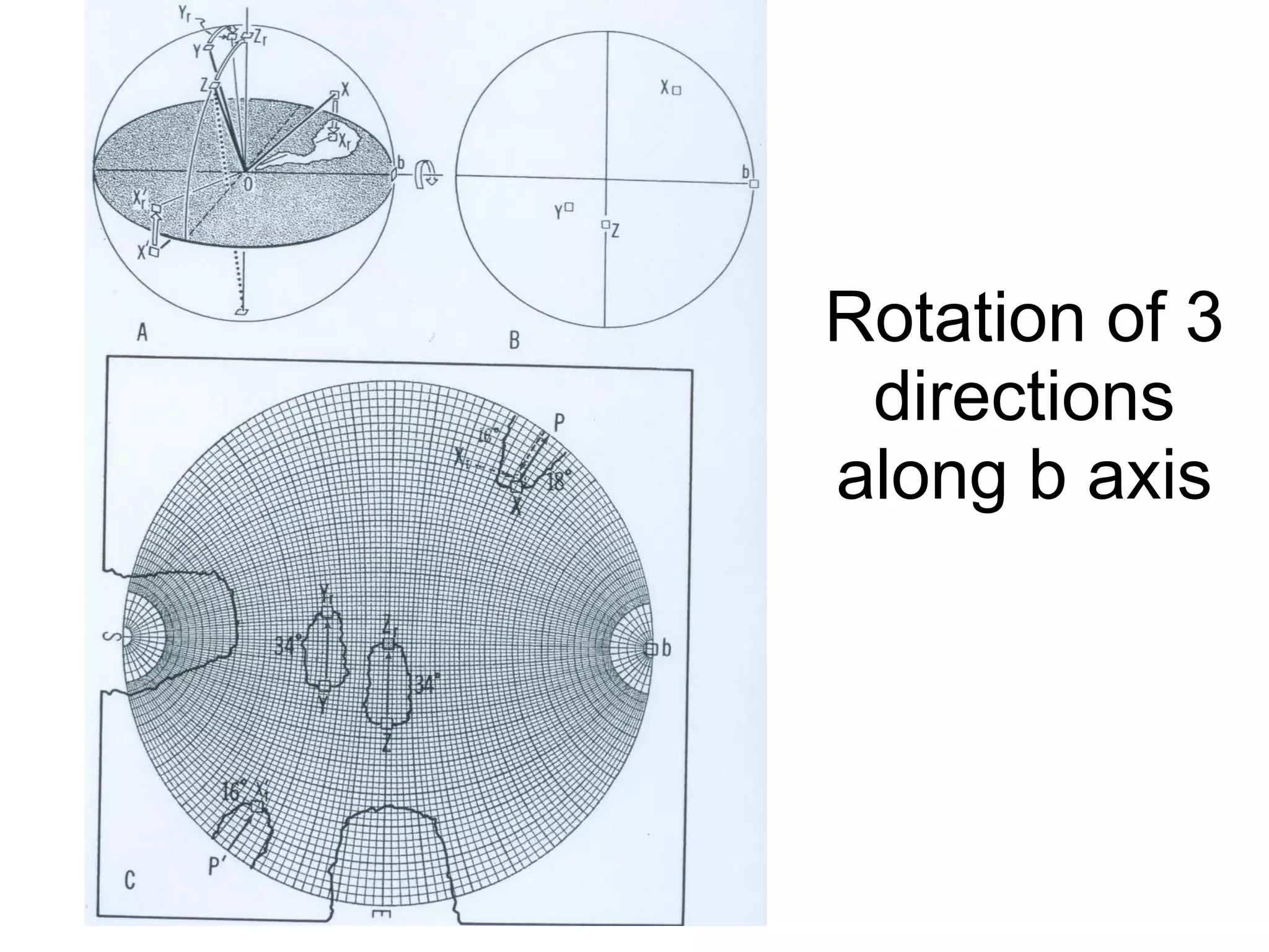
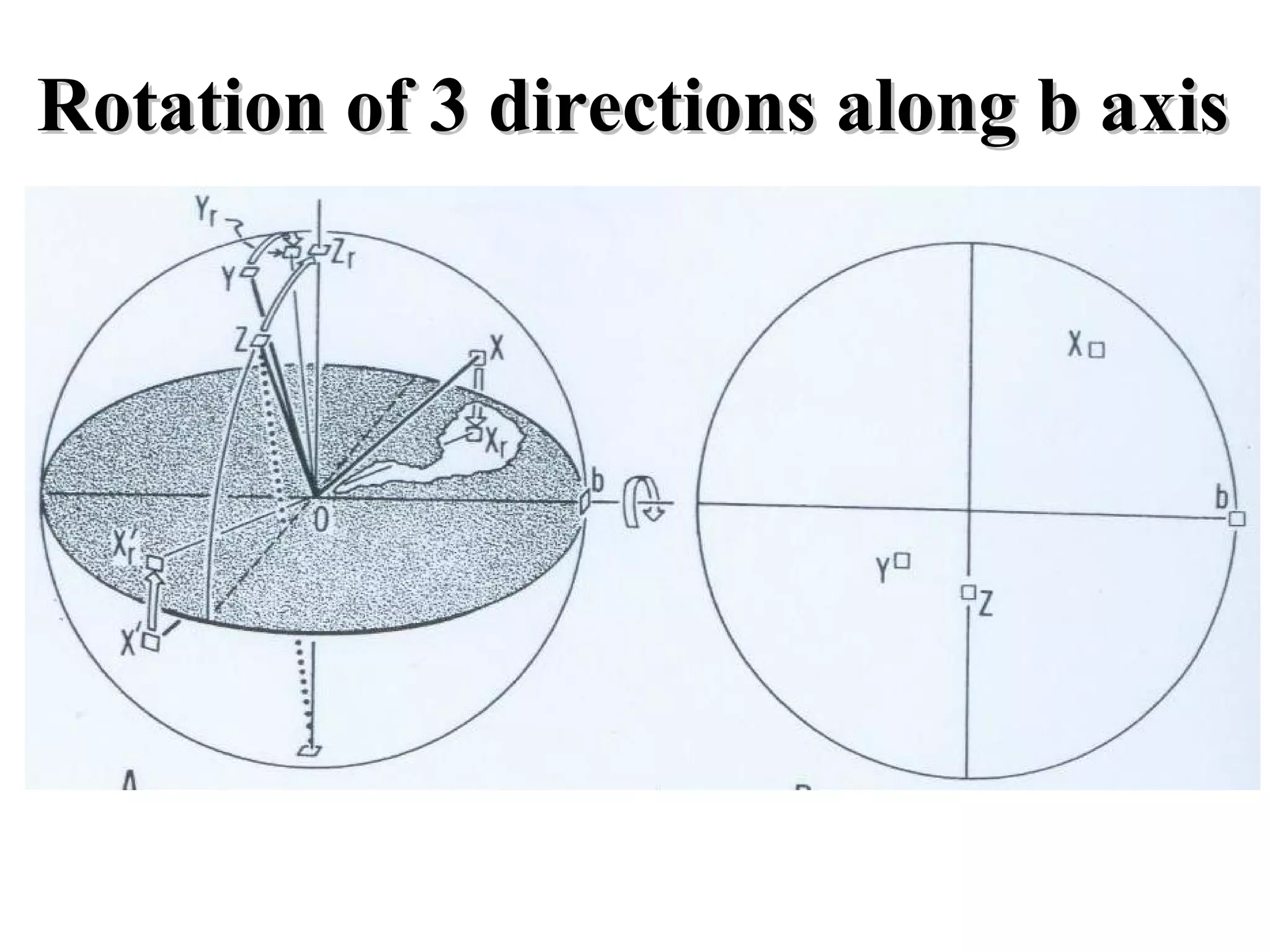
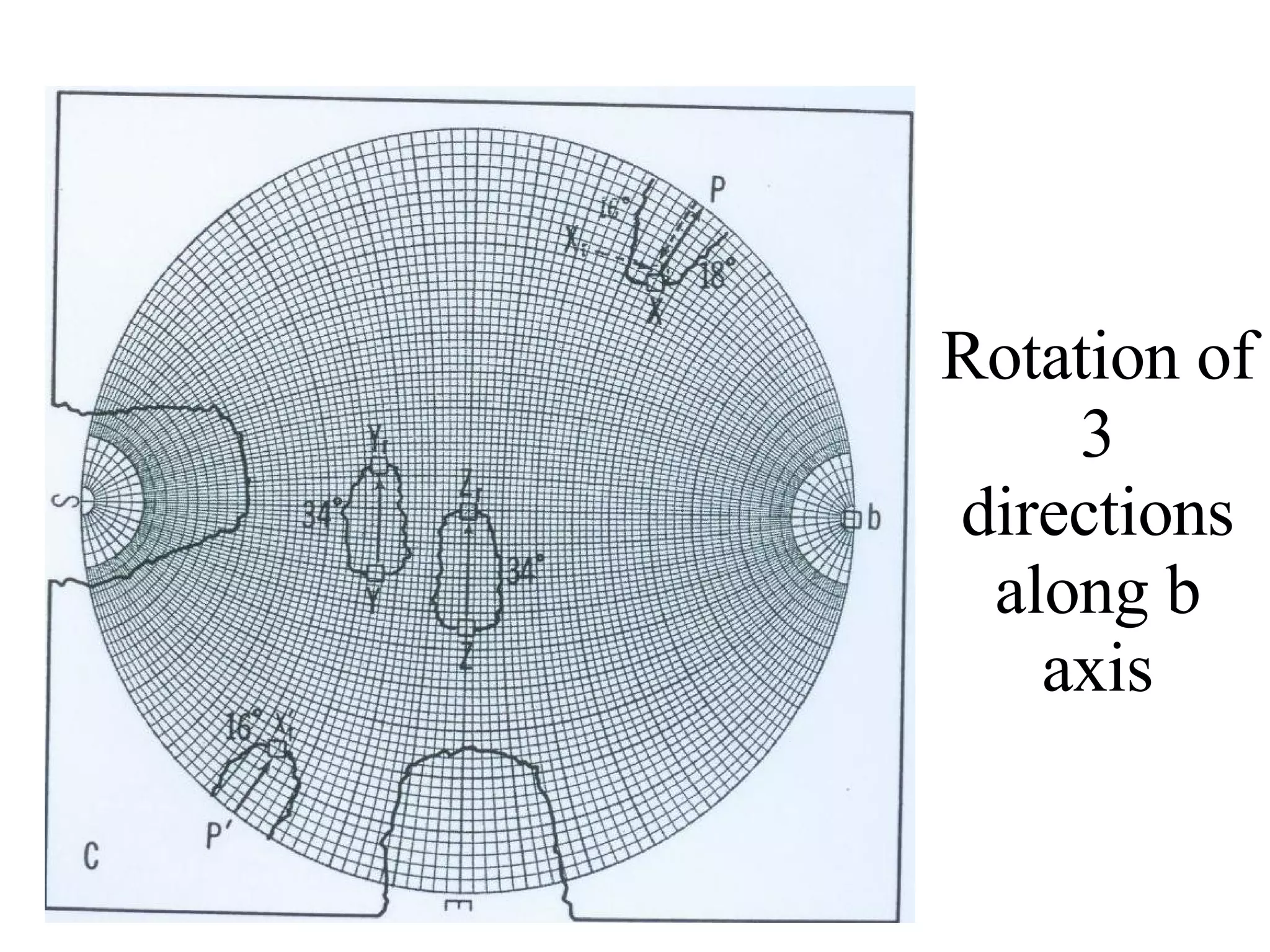
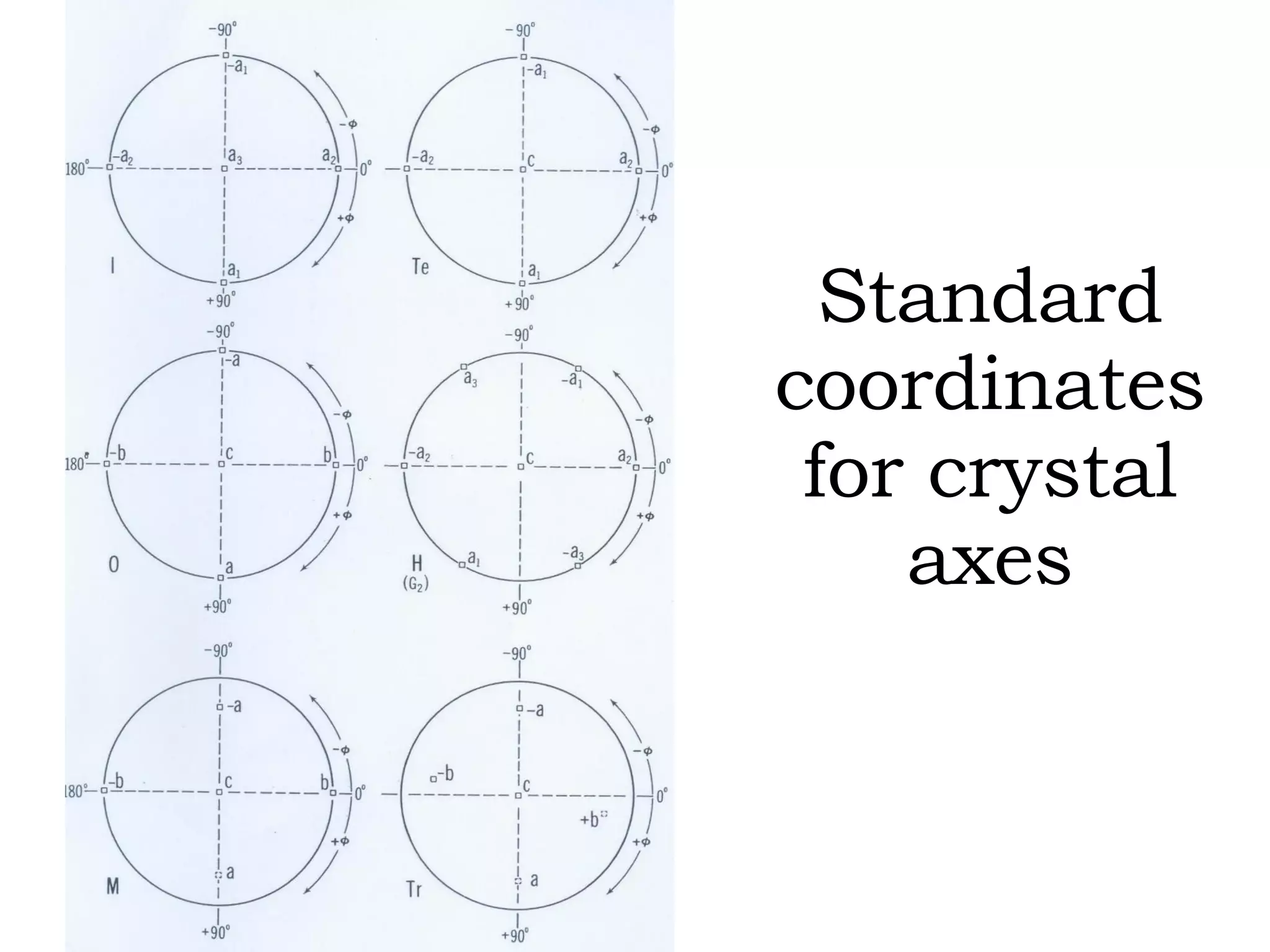
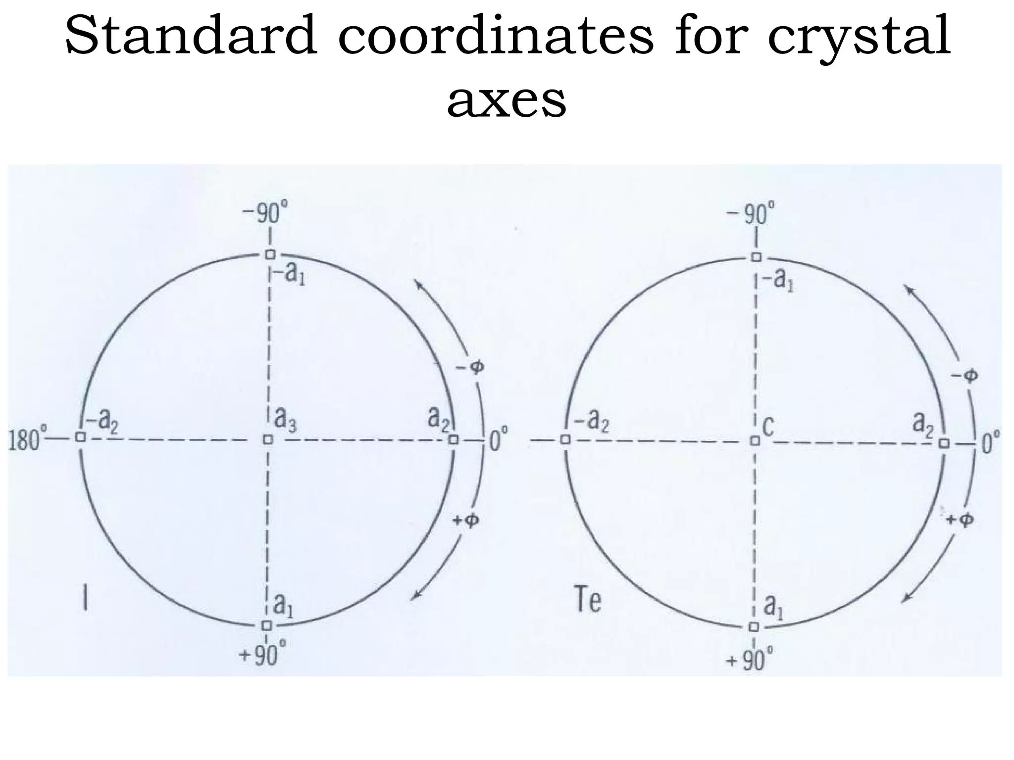
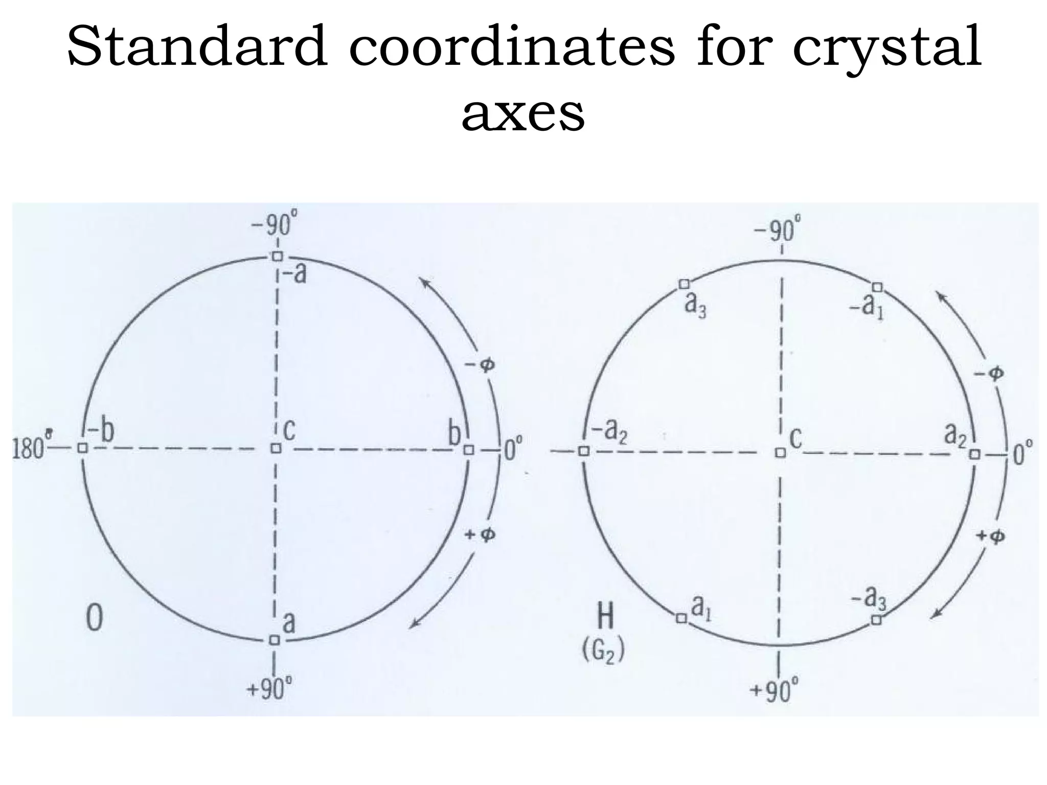
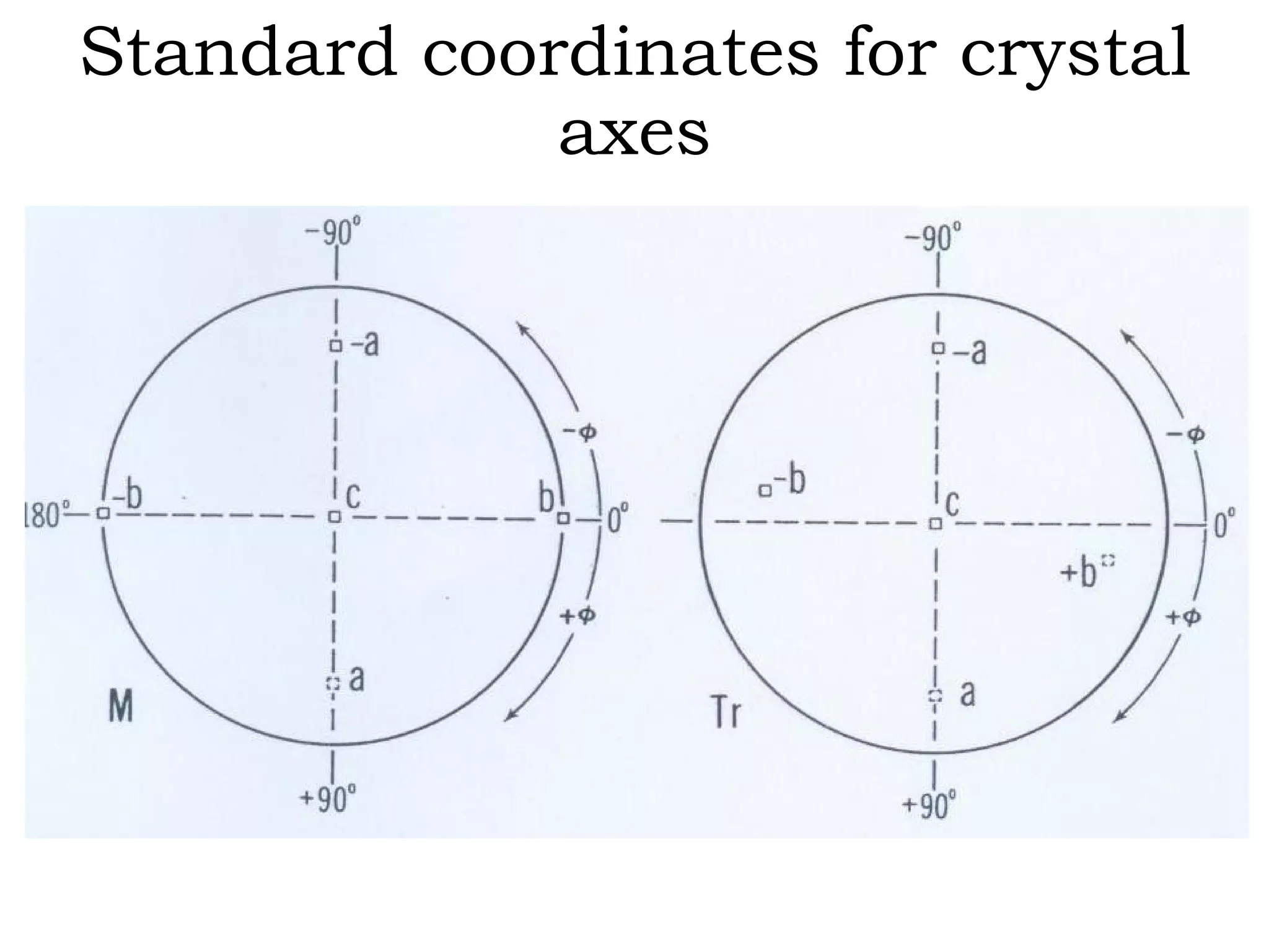
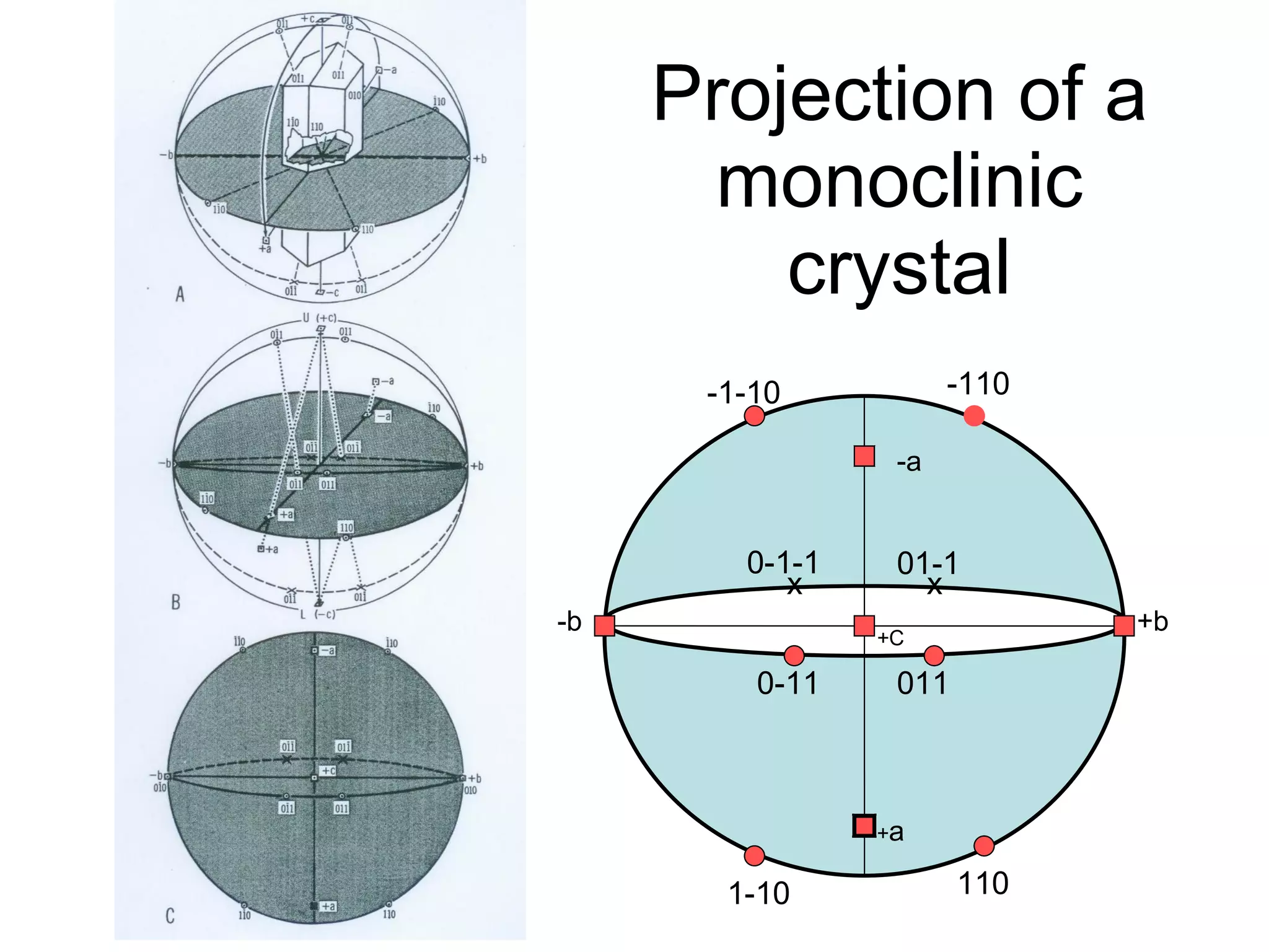
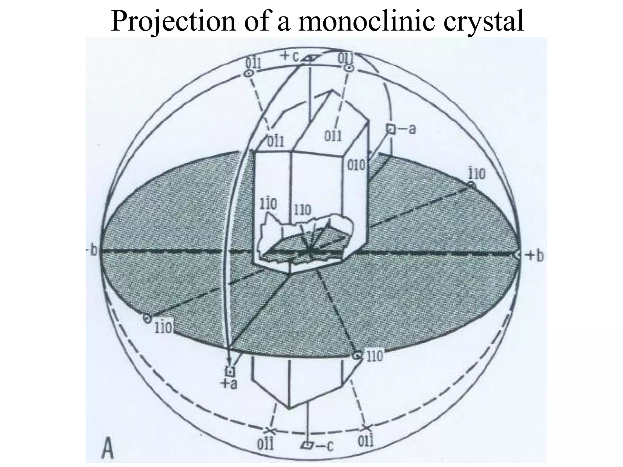
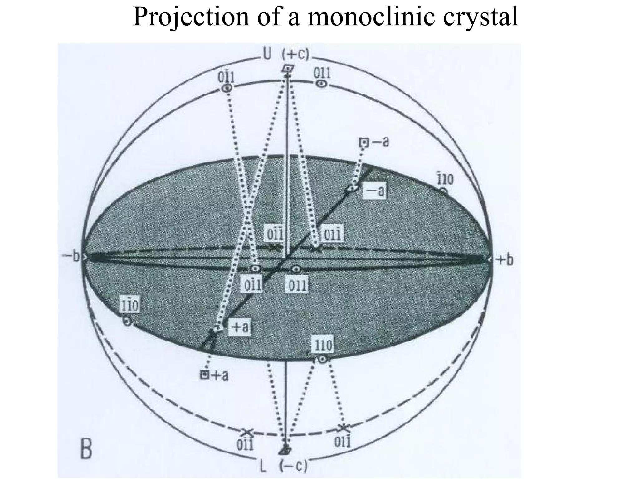
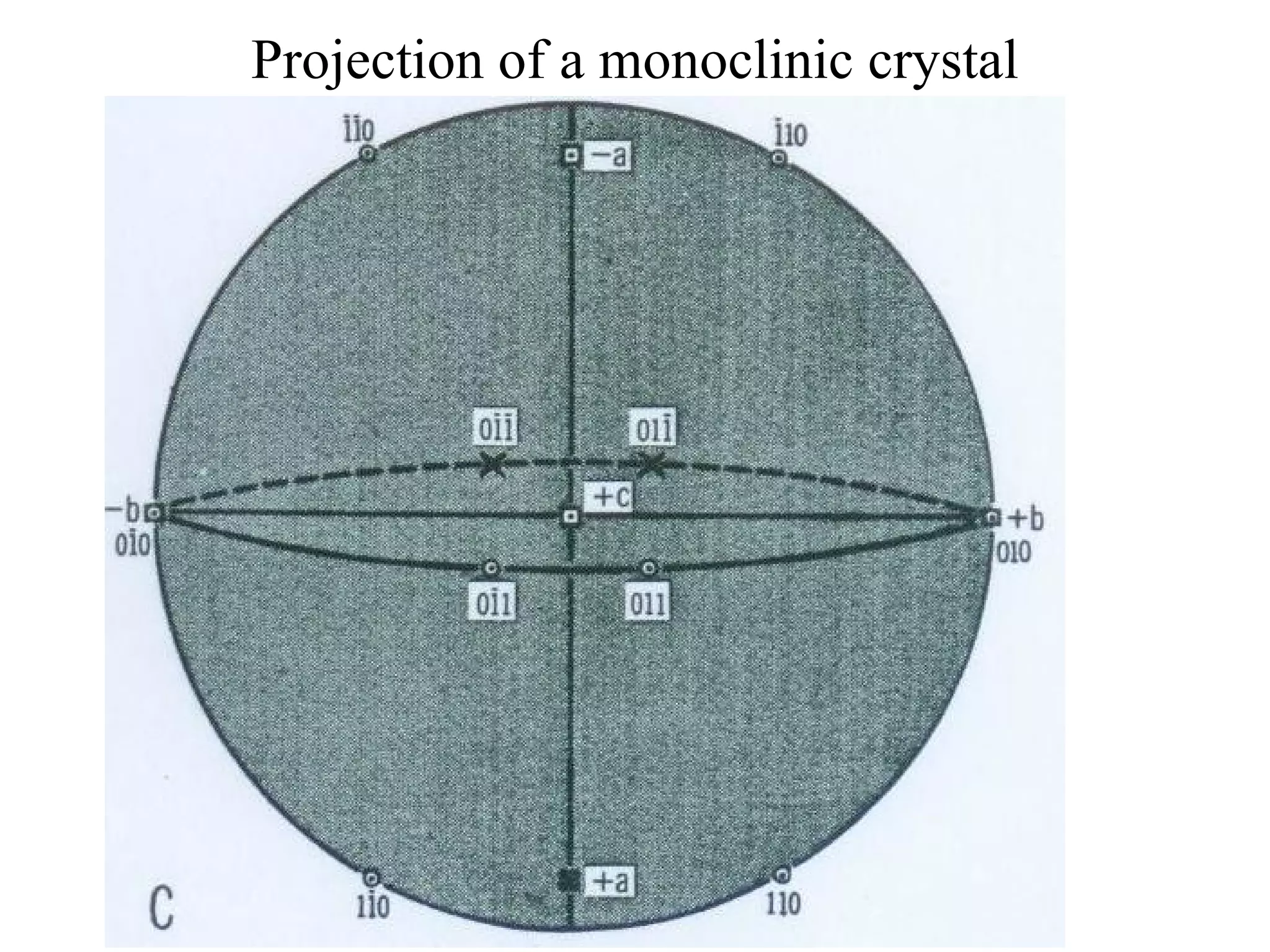
- Stereographic projections for representing crystallographic planes and directions.
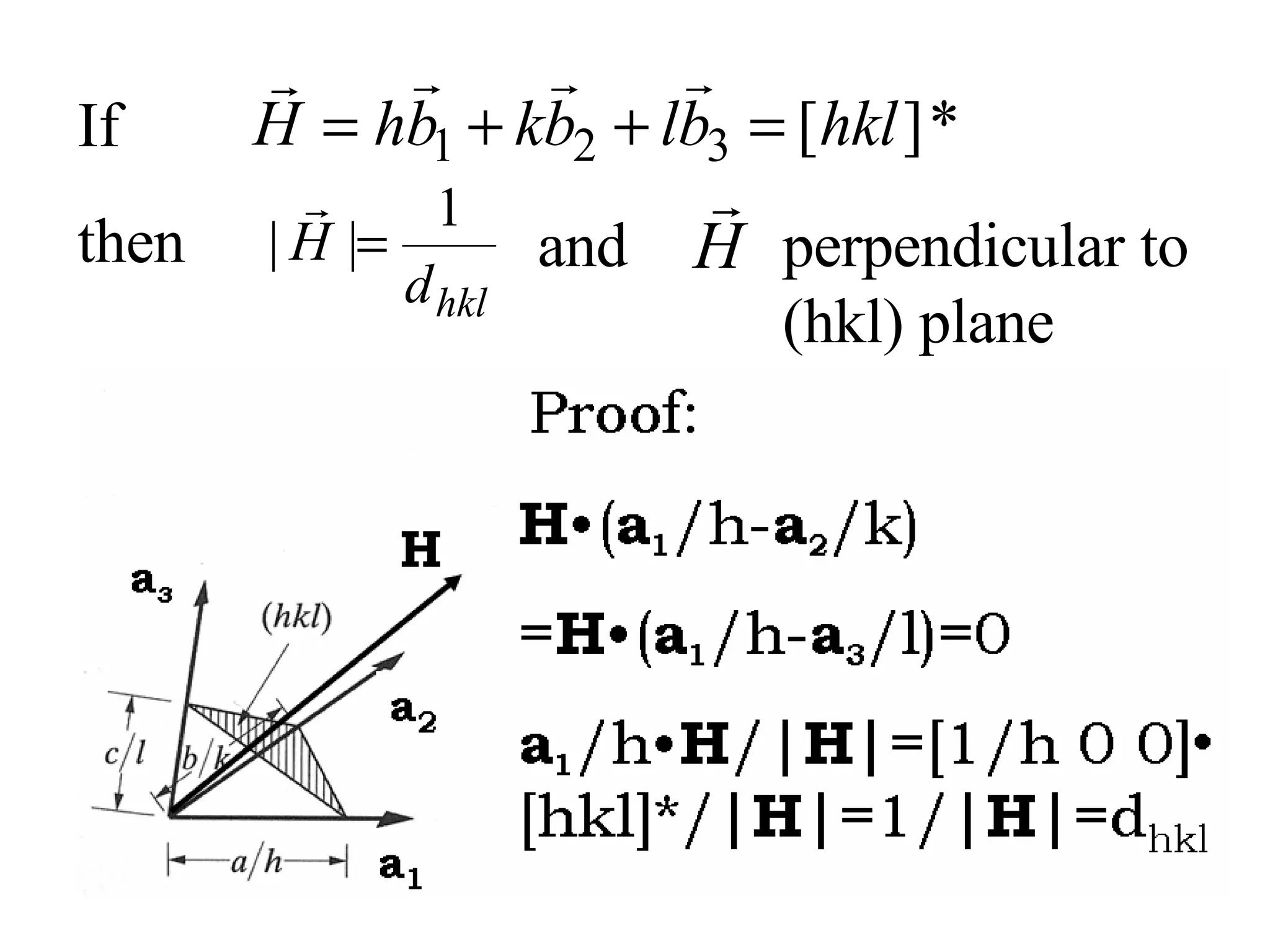
![If then and perpendicular to (hkl) plane Proof: H • ( a 1 /h- a 2 /k) = H • ( a 1 /h- a 3 /l)=0 a 1 /h• H /| H |=[1/h 0 0] • [hkl]*/| H |=1/| H |=d hkl H a 1 a 2 a 3](https://image.slidesharecdn.com/972b3102005cullitychapter2-090427075953-phpapp01/75/972-B3102005-Cullity-Chapter-2-13-2048.jpg)
![Zone axis [uvw] Zone plane (hkl) then hu+kv+wl=0 Two zone planes (h 1 k 1 l 1 ) and (h 2 k 2 l 2 ) then zone axis [uvw]=](https://image.slidesharecdn.com/972b3102005cullitychapter2-090427075953-phpapp01/75/972-B3102005-Cullity-Chapter-2-31-2048.jpg)
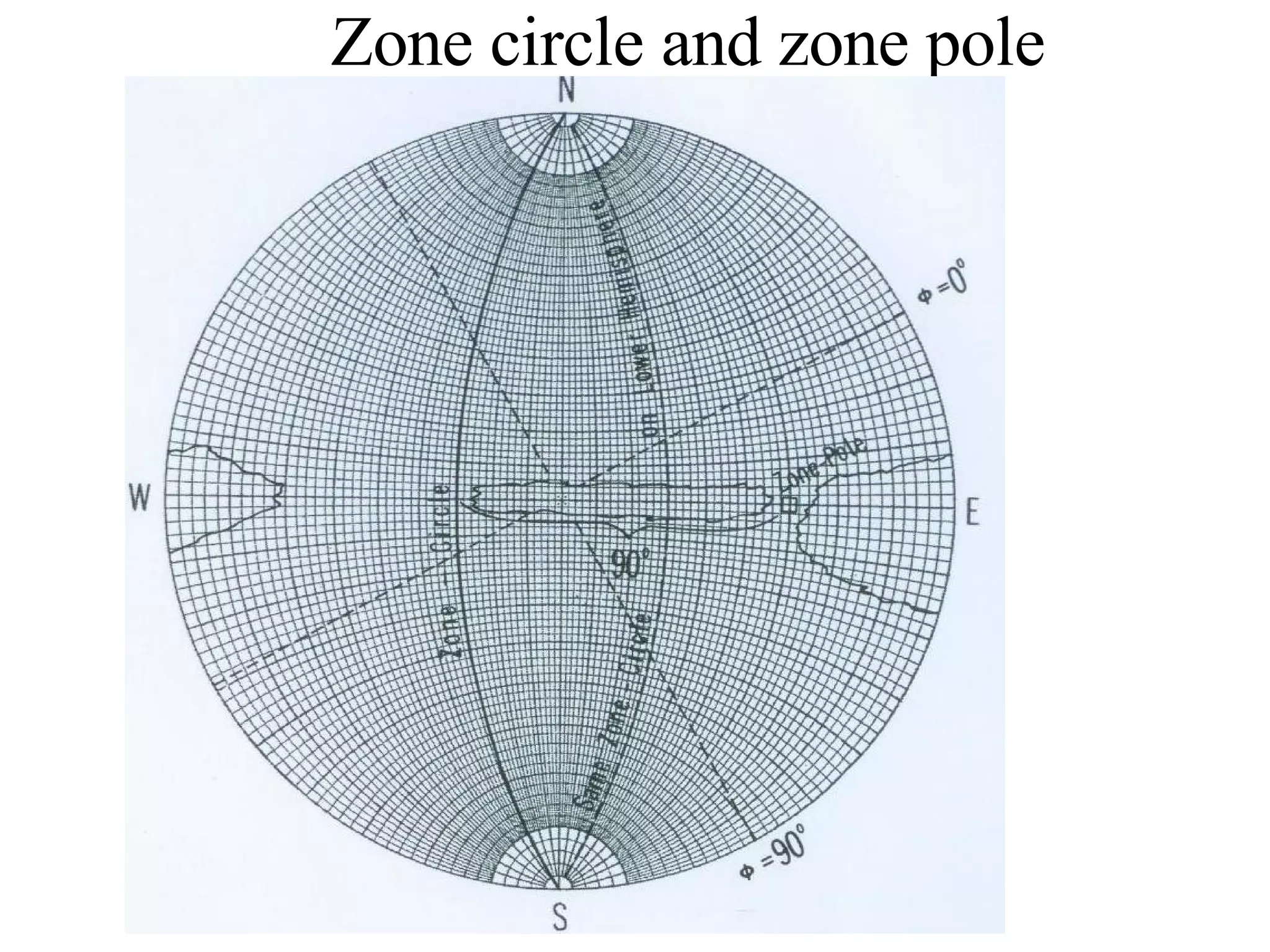
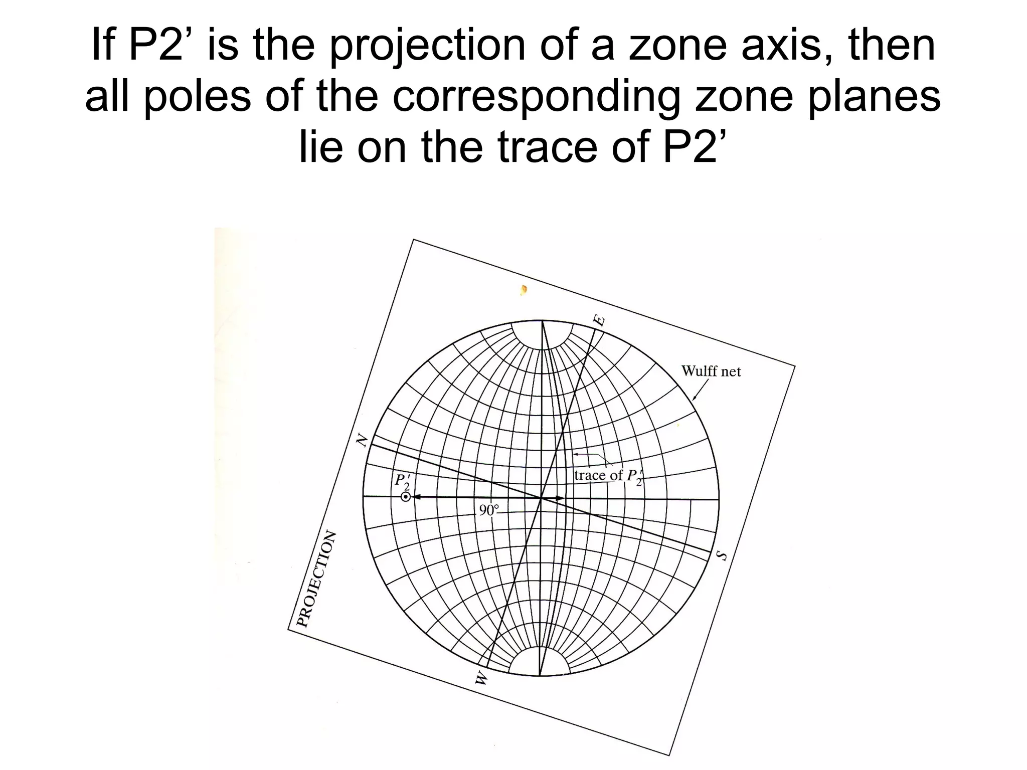
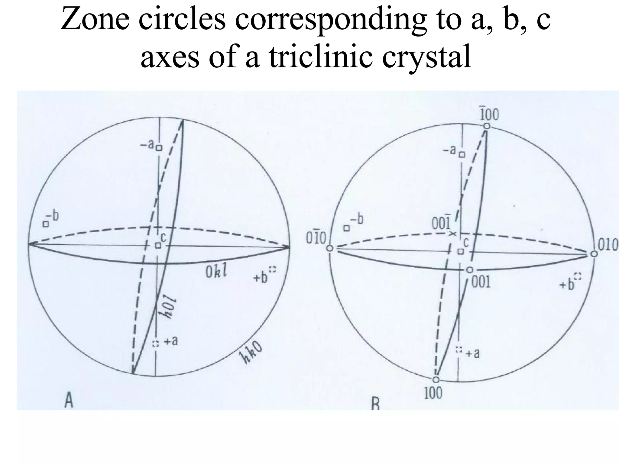
![(a) Zone plane (stippled) (b) zone circle with zone axis ā, note [100] • [0xx]=0](https://image.slidesharecdn.com/972b3102005cullitychapter2-090427075953-phpapp01/75/972-B3102005-Cullity-Chapter-2-89-2048.jpg)