Downloaded 1,076 times
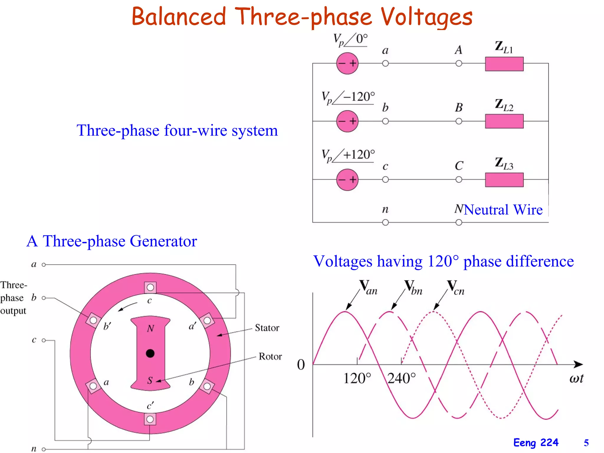
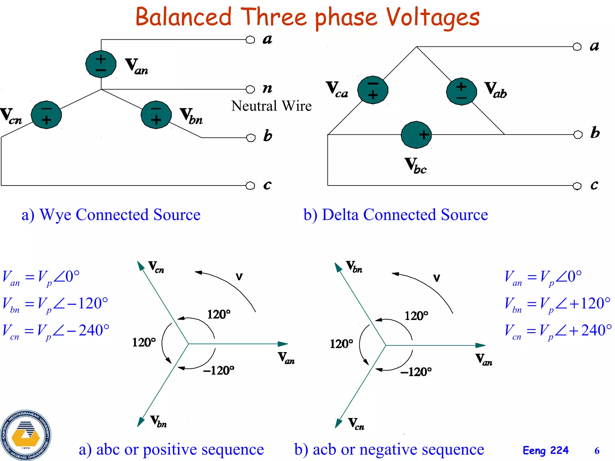
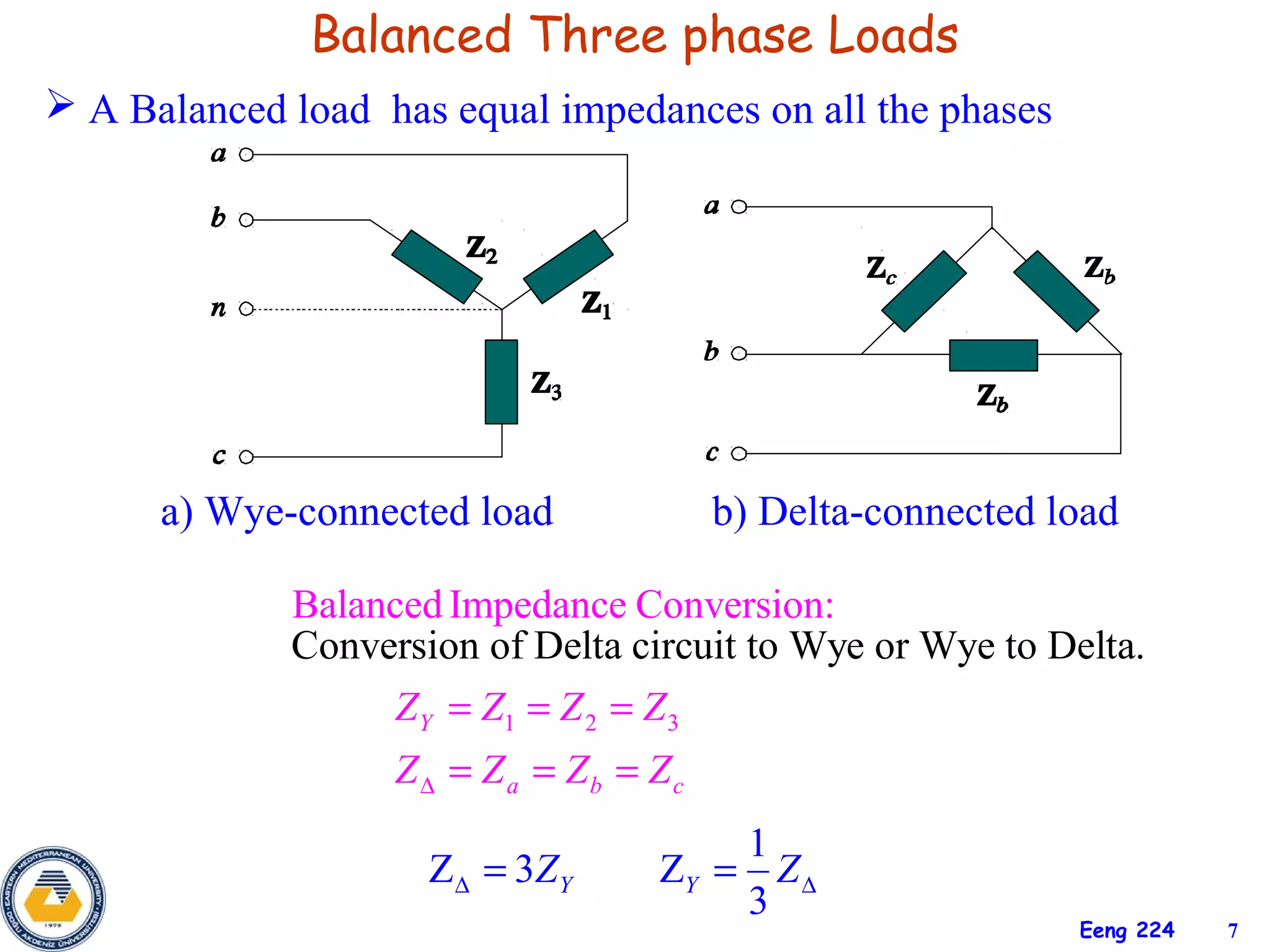
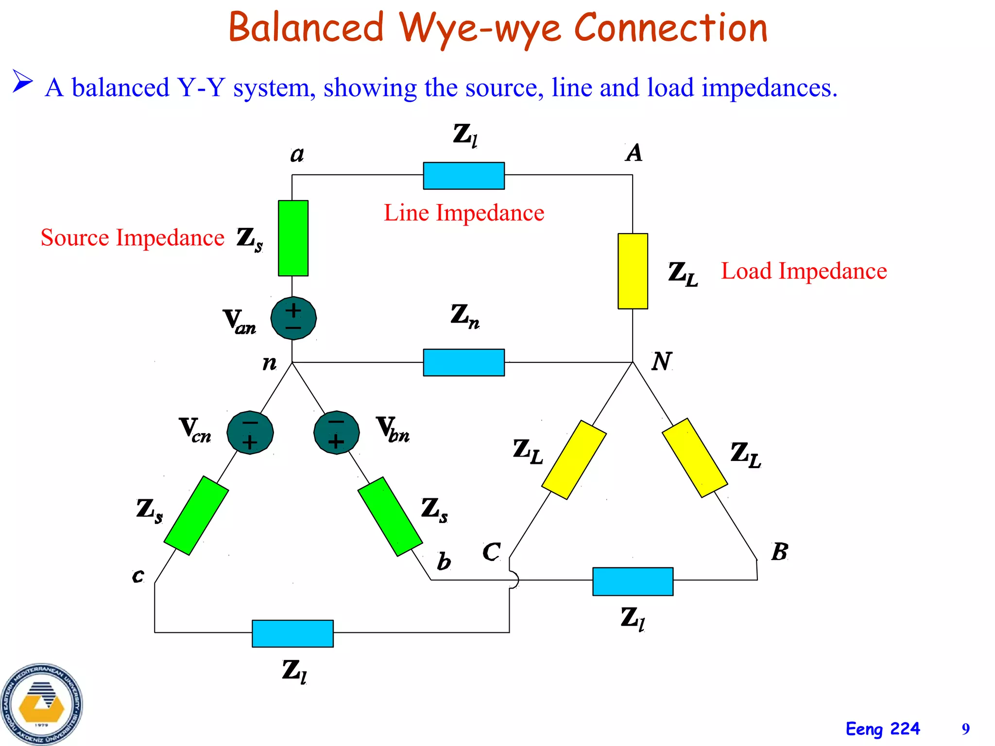
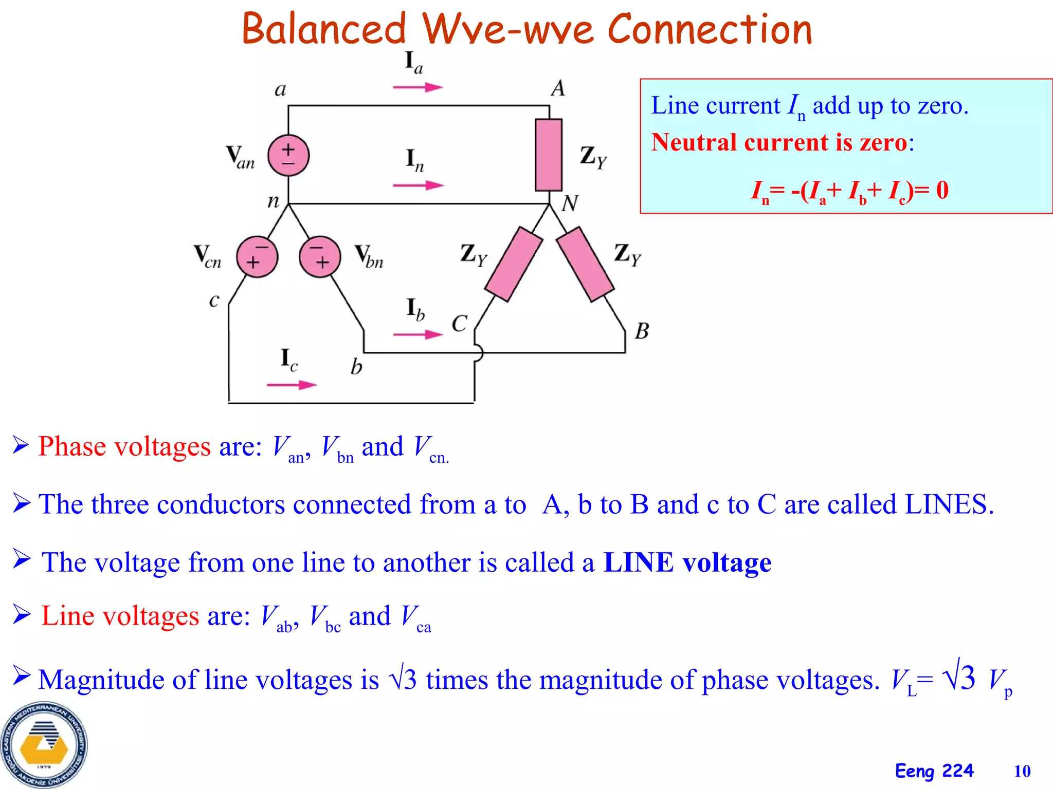
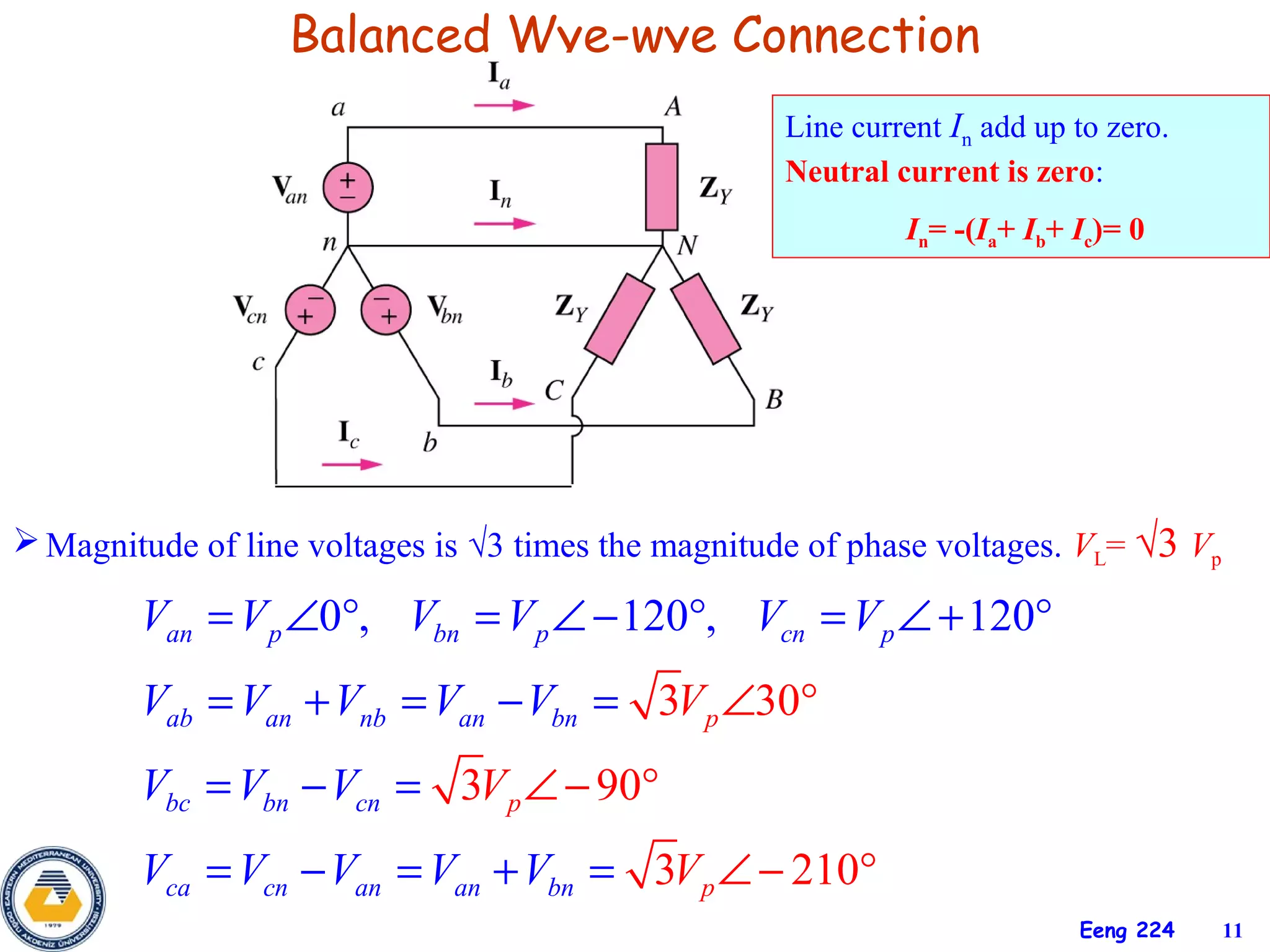
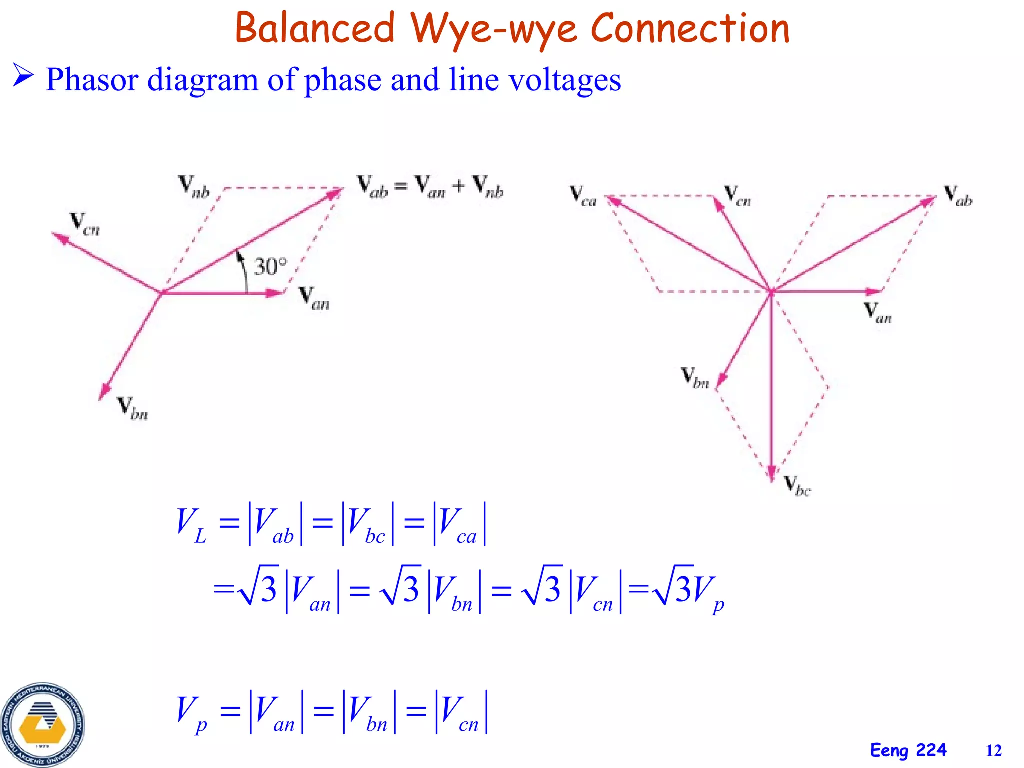
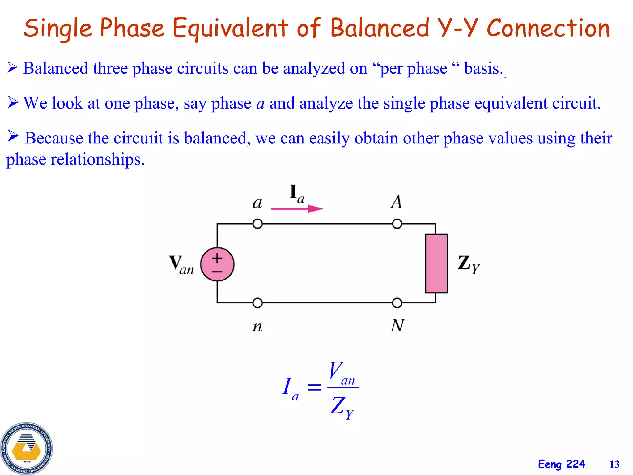
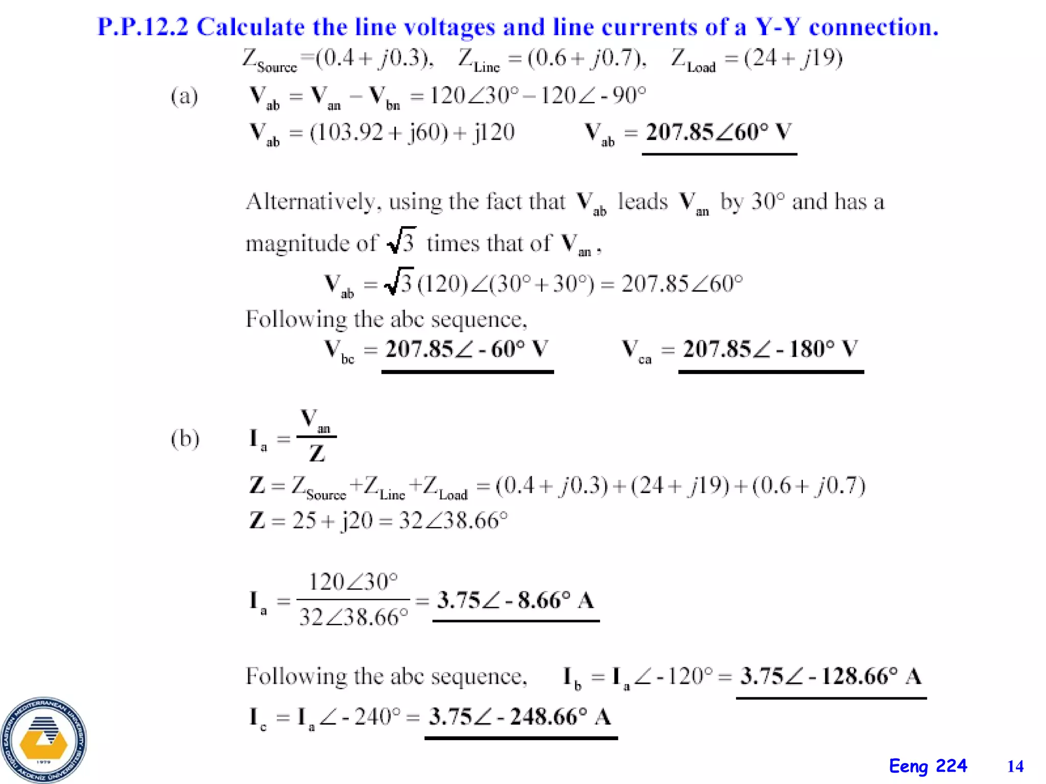
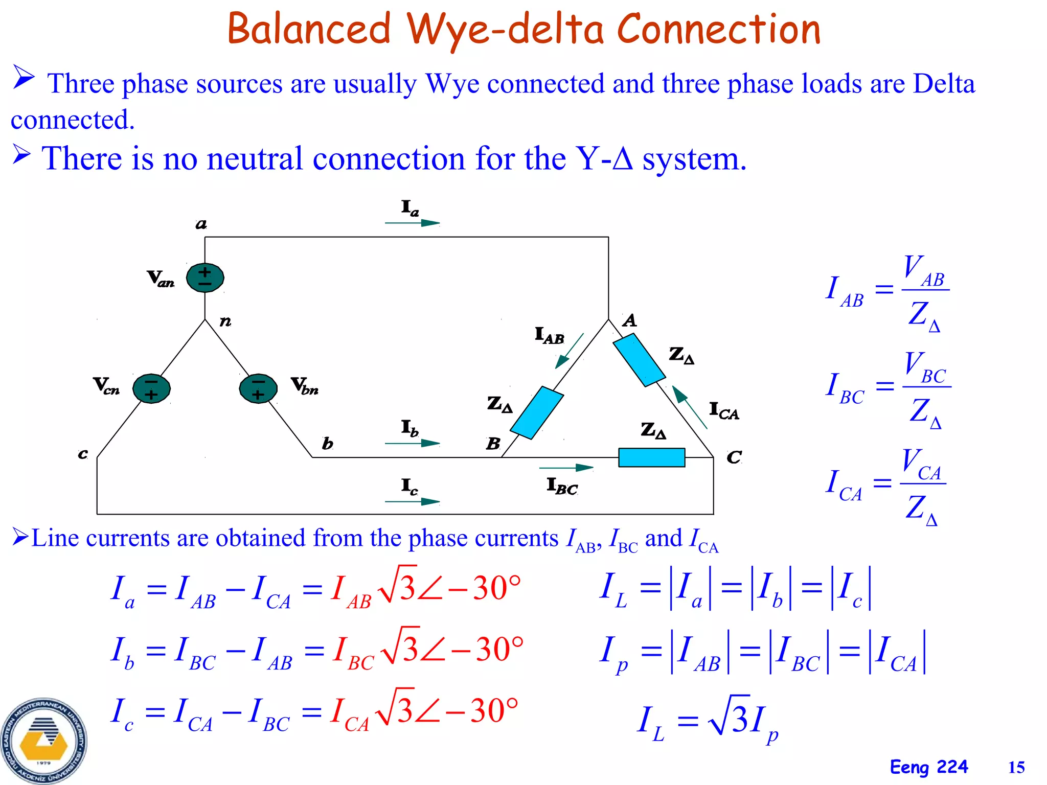
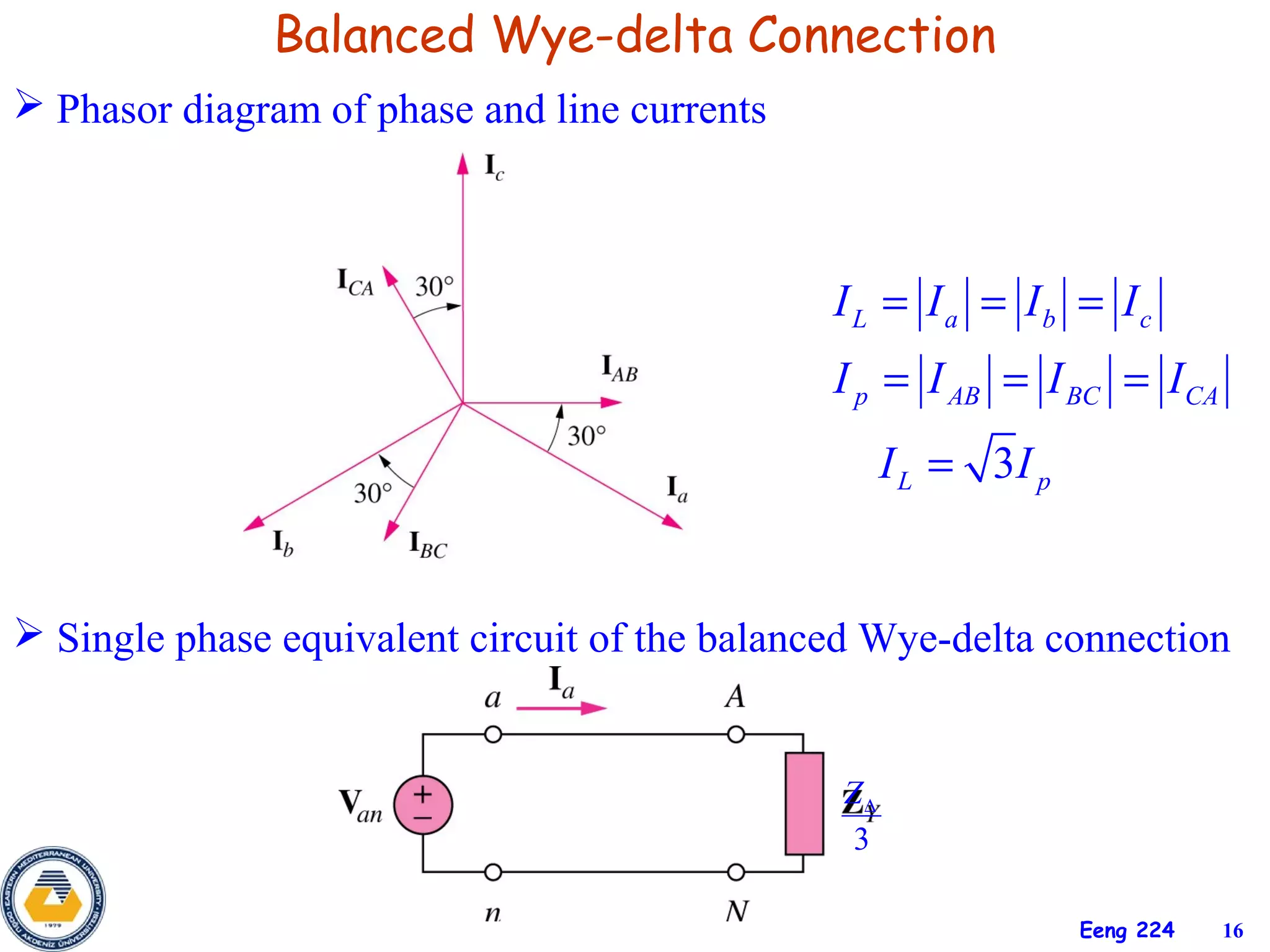
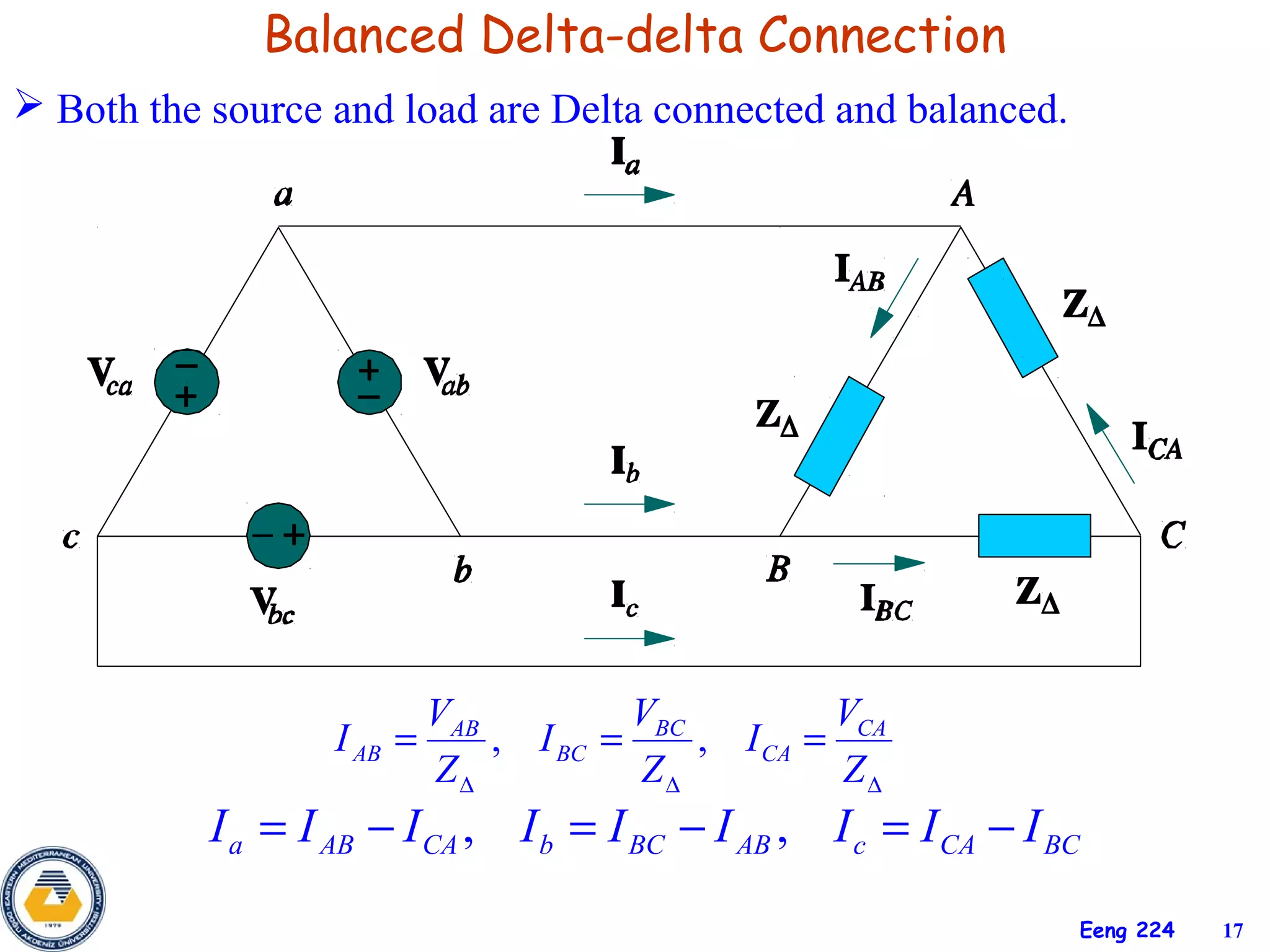
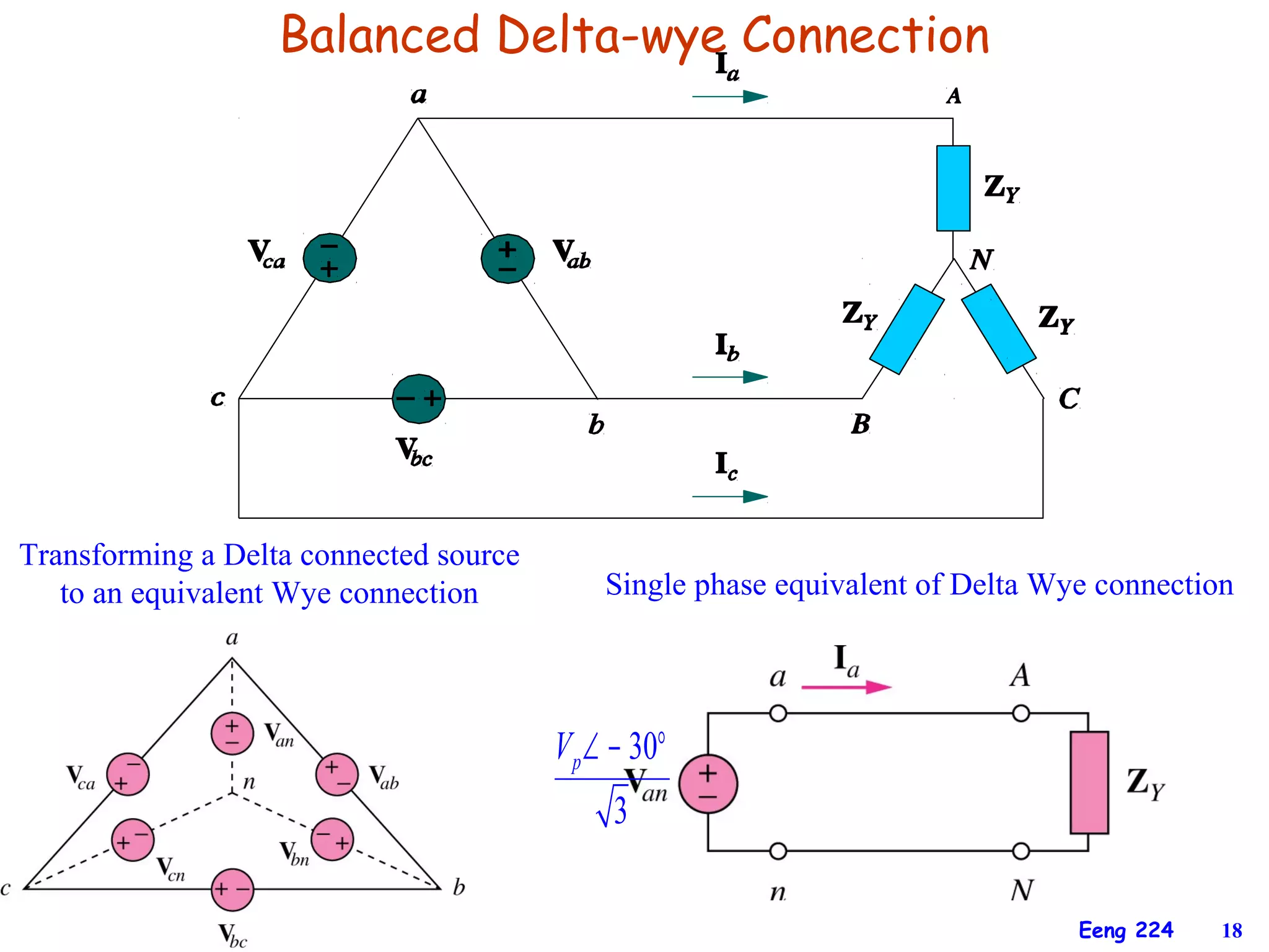

The document discusses three-phase circuits and their analysis. It covers balanced and unbalanced three-phase configurations, power in balanced systems, and analyzing unbalanced systems using PSpice. The objectives are to understand different three-phase connections, distinguish balanced and unbalanced circuits, calculate power in balanced systems, analyze unbalanced systems, and apply the concepts to measurement and residential wiring. Key points covered include wye-wye, wye-delta, delta-delta, and delta-wye connections for both sources and loads.


