Downloaded 873 times
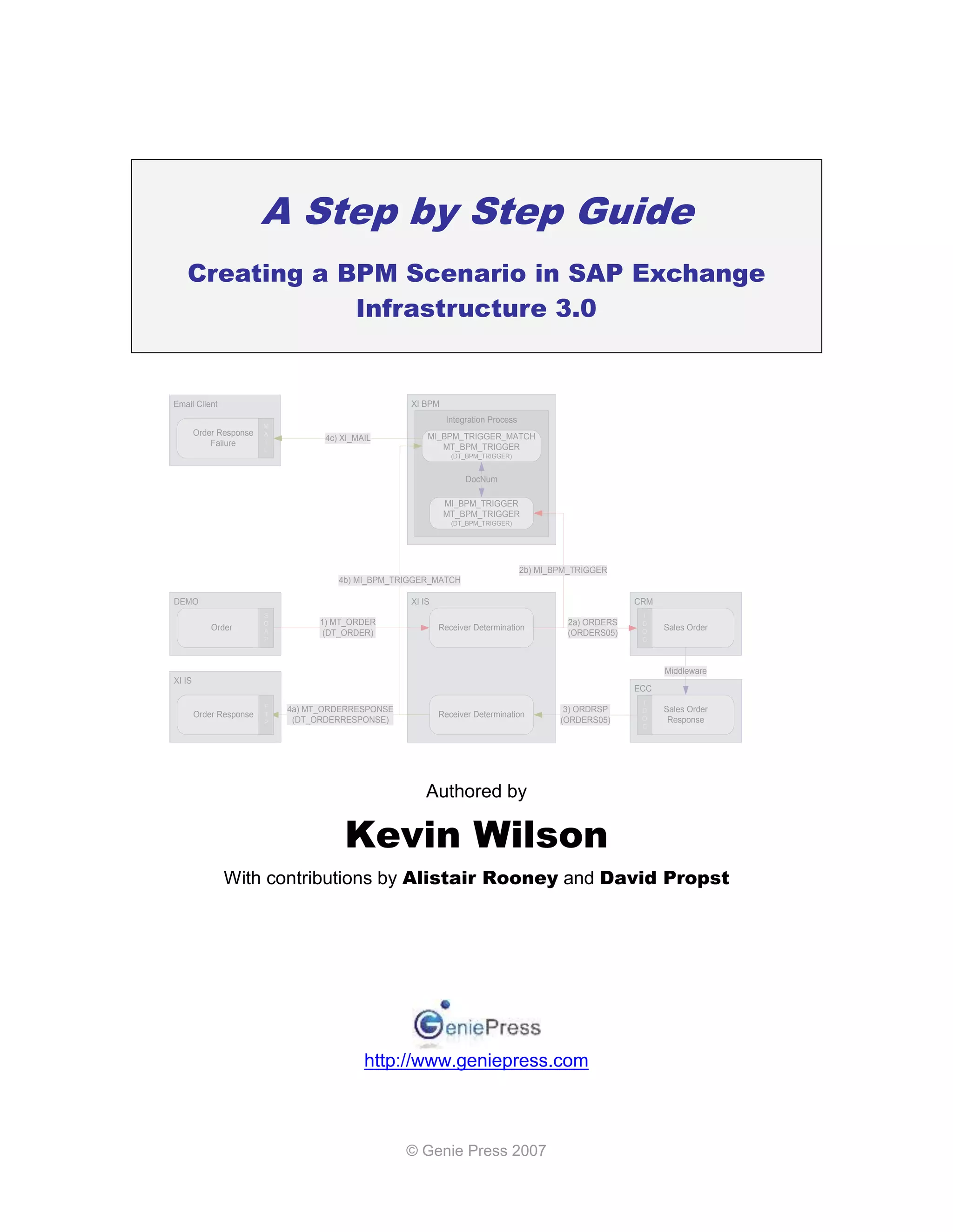

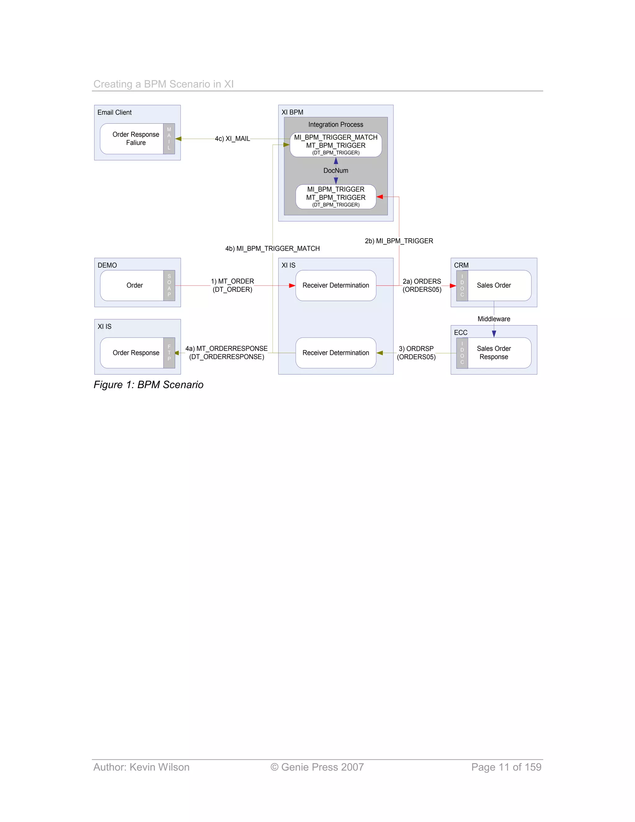
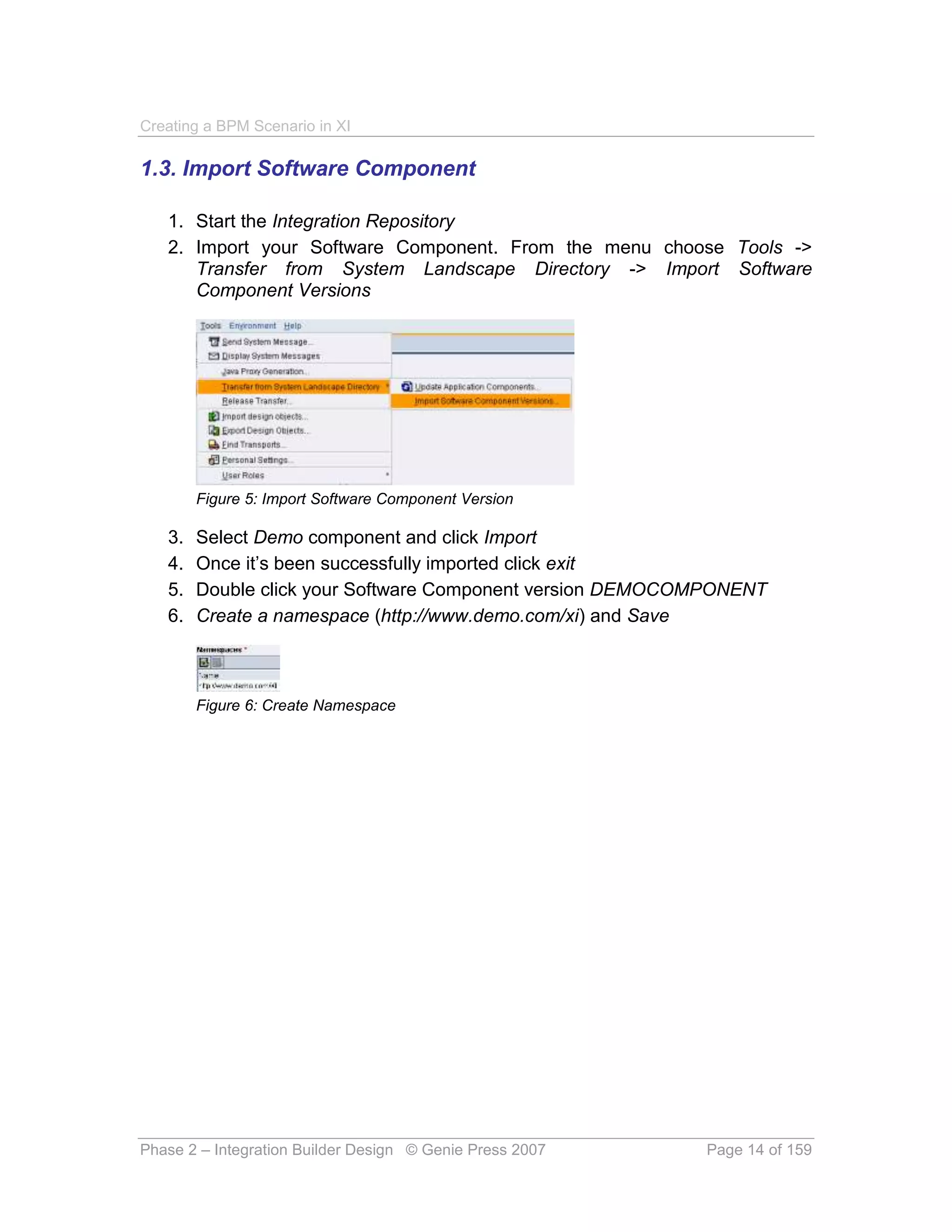
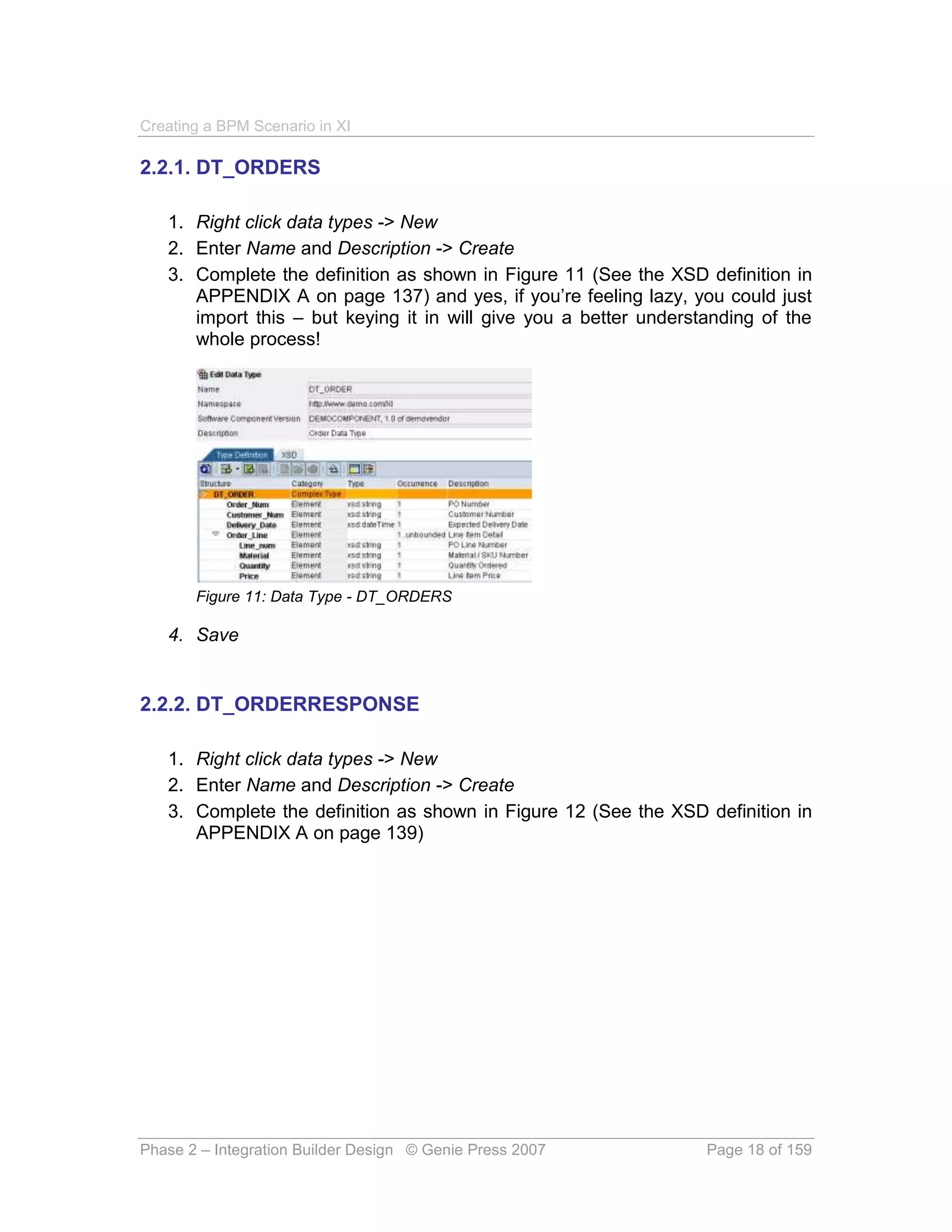
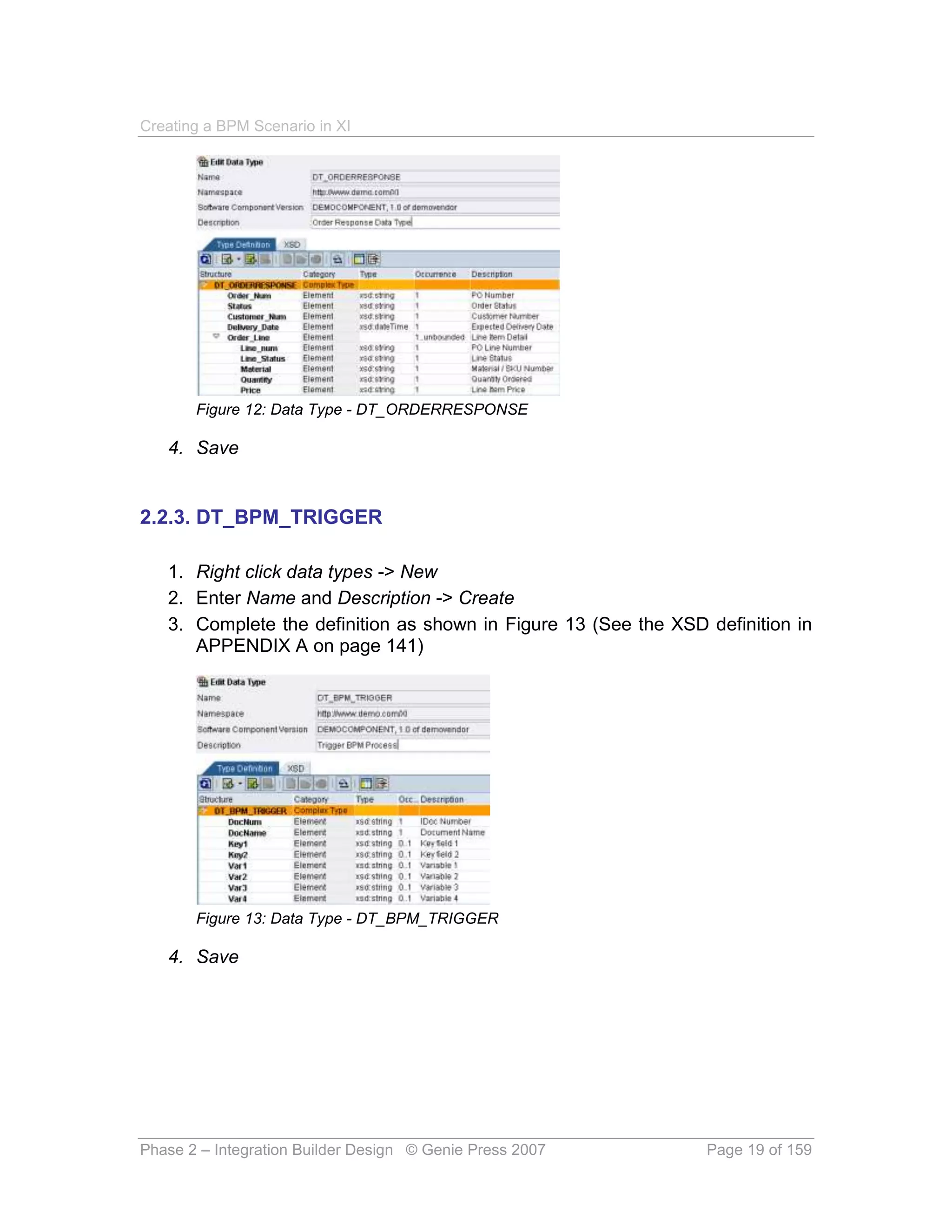
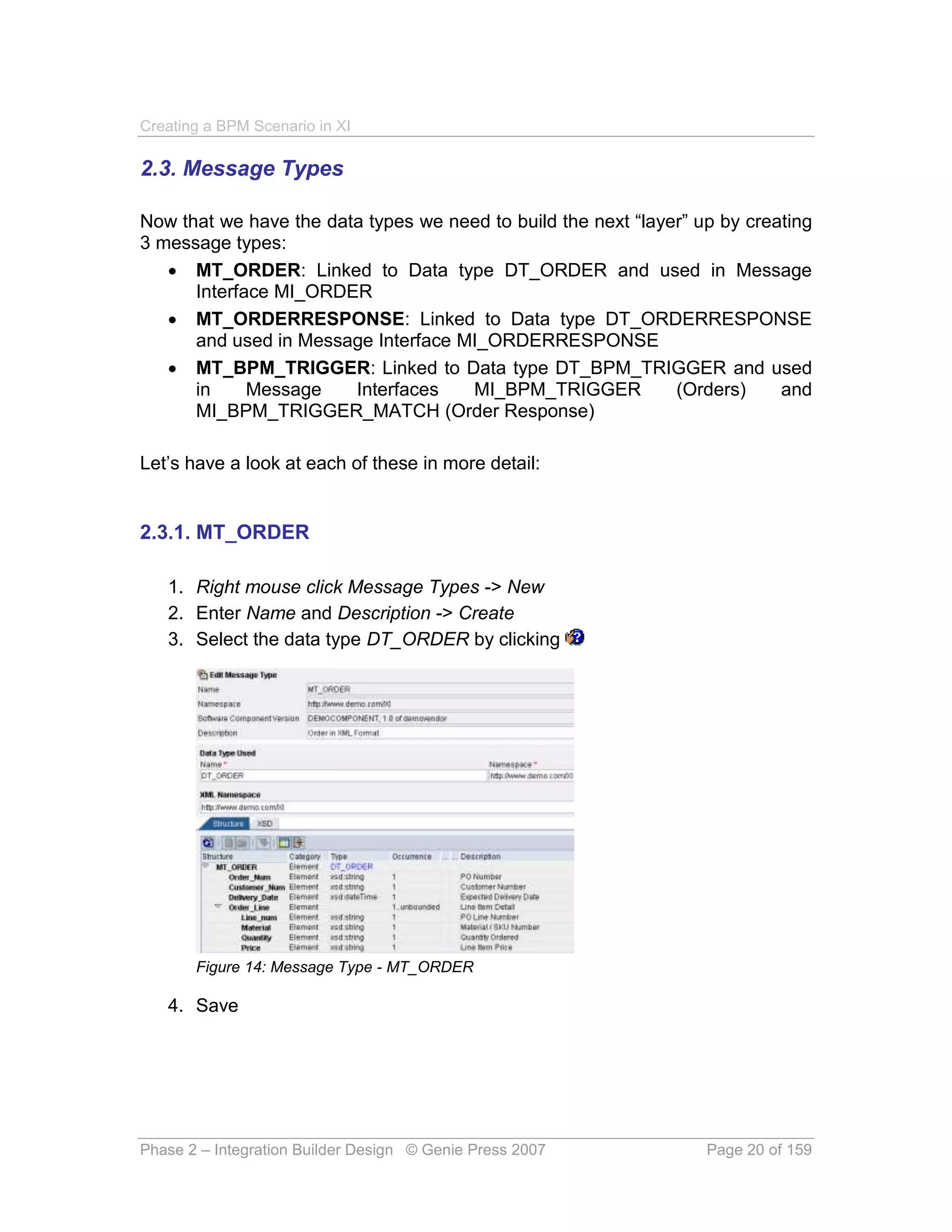
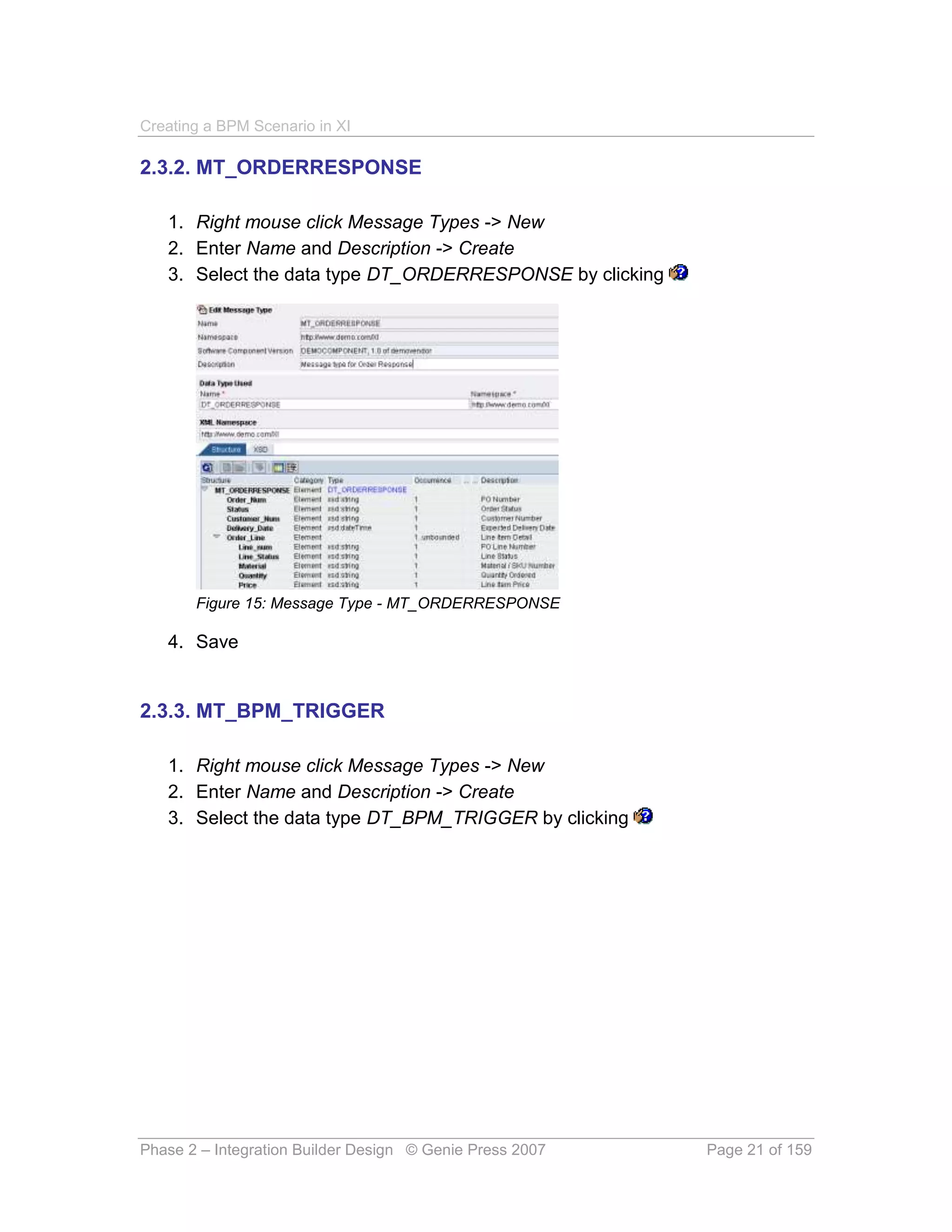
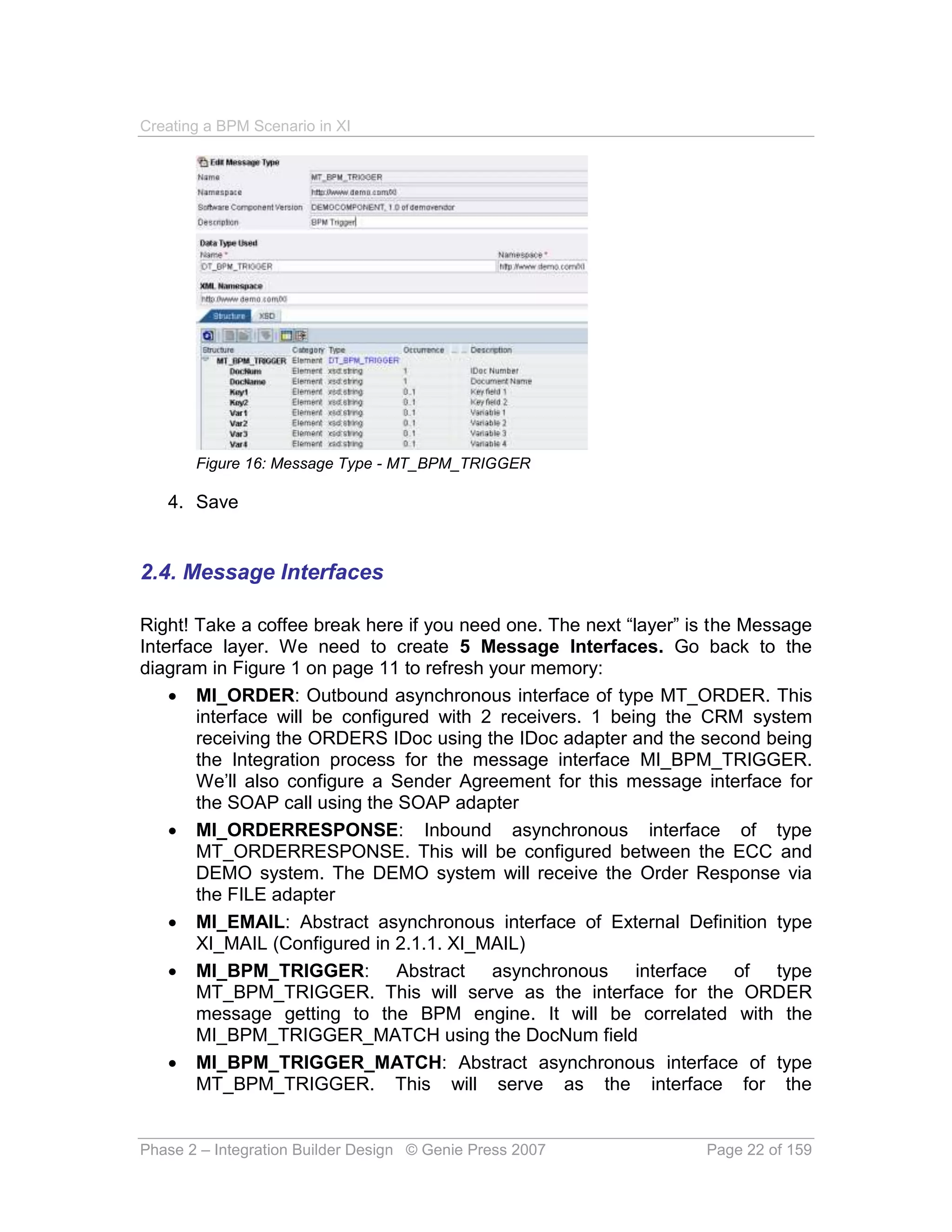
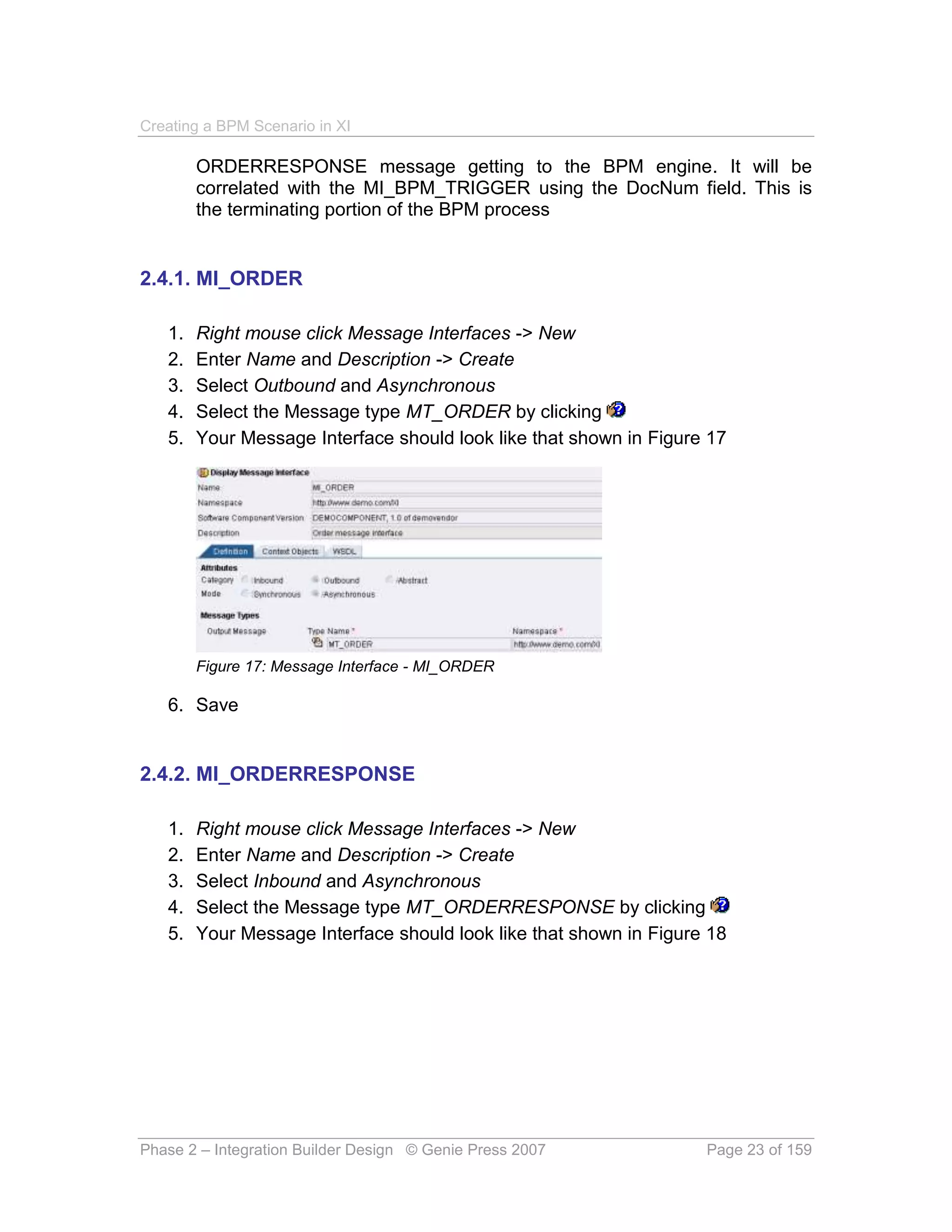
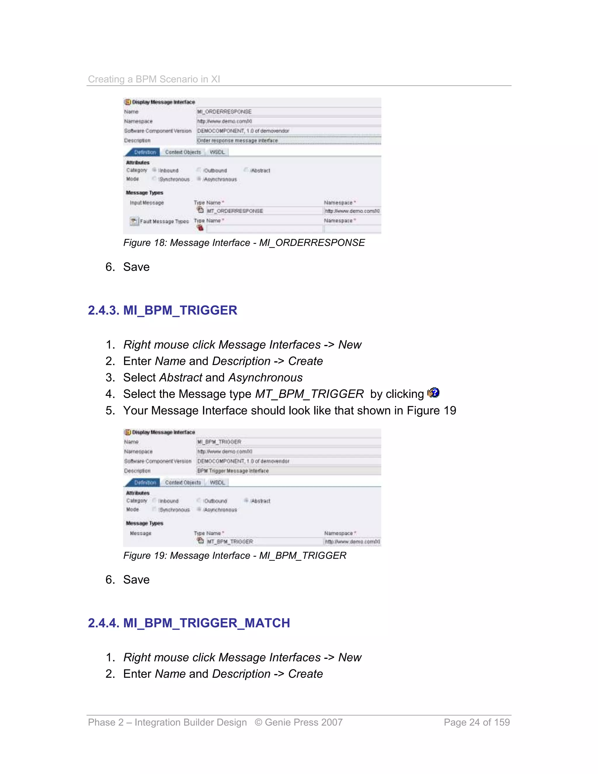
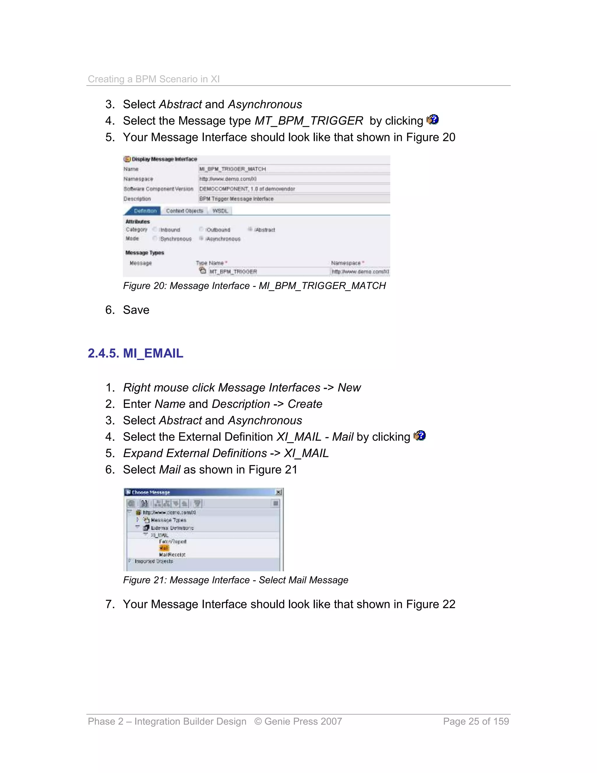
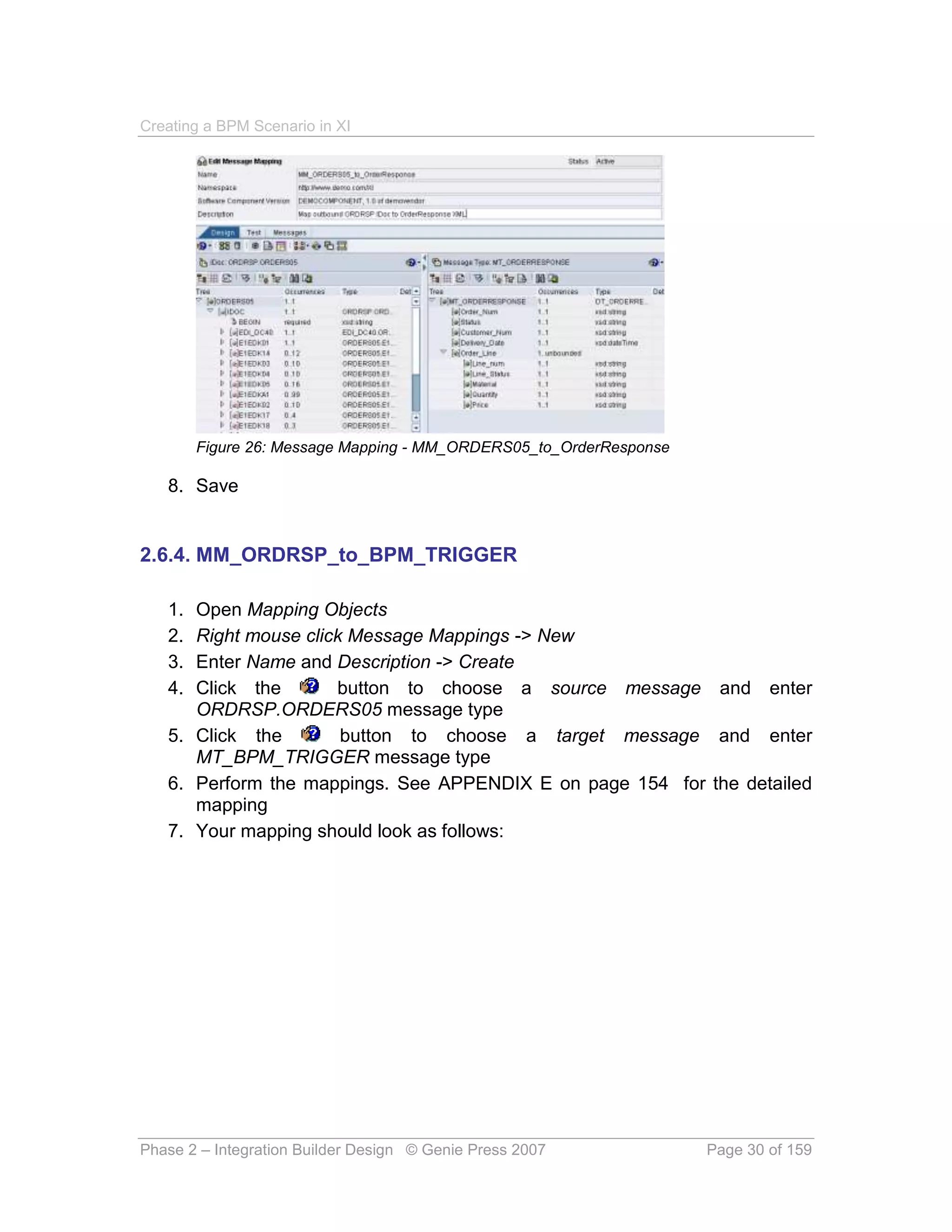
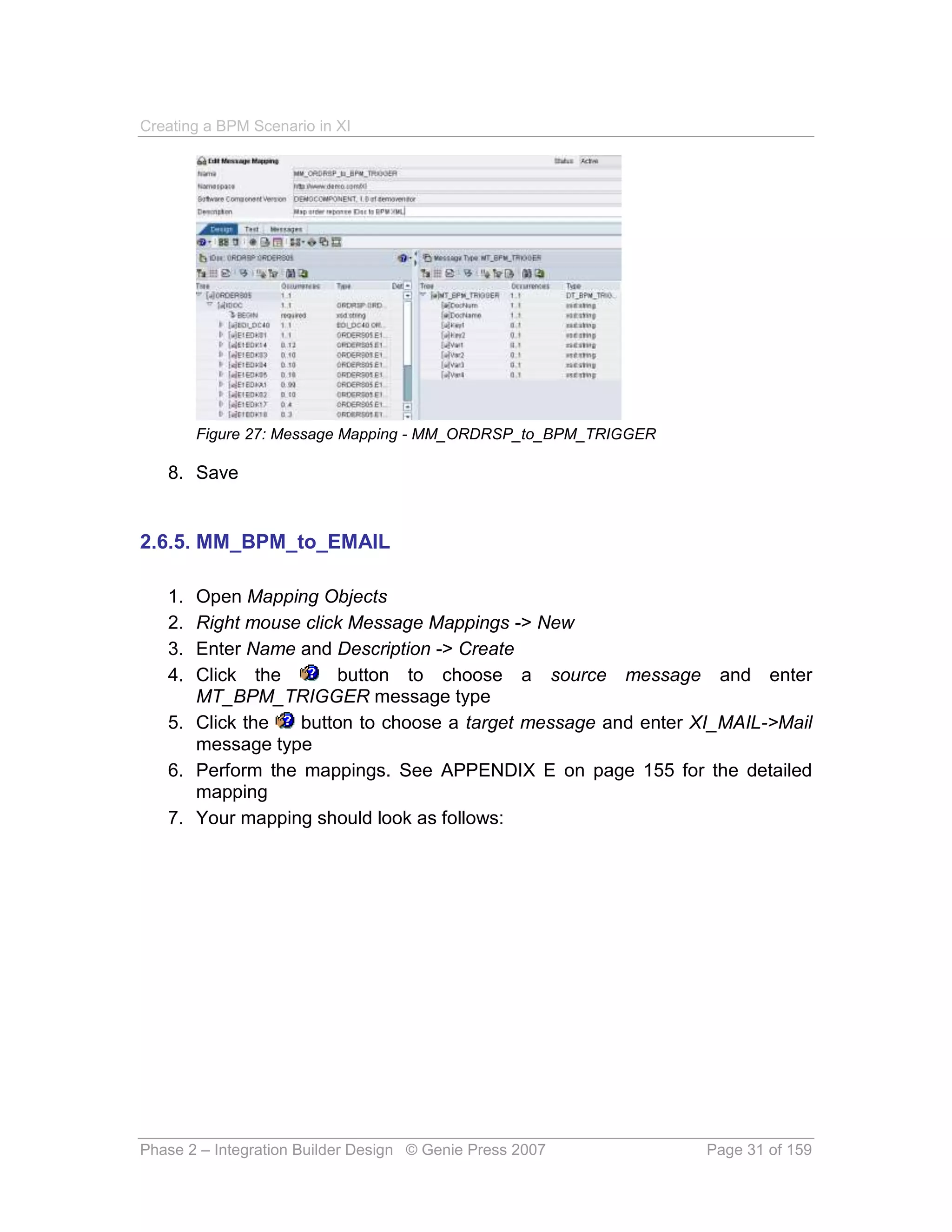
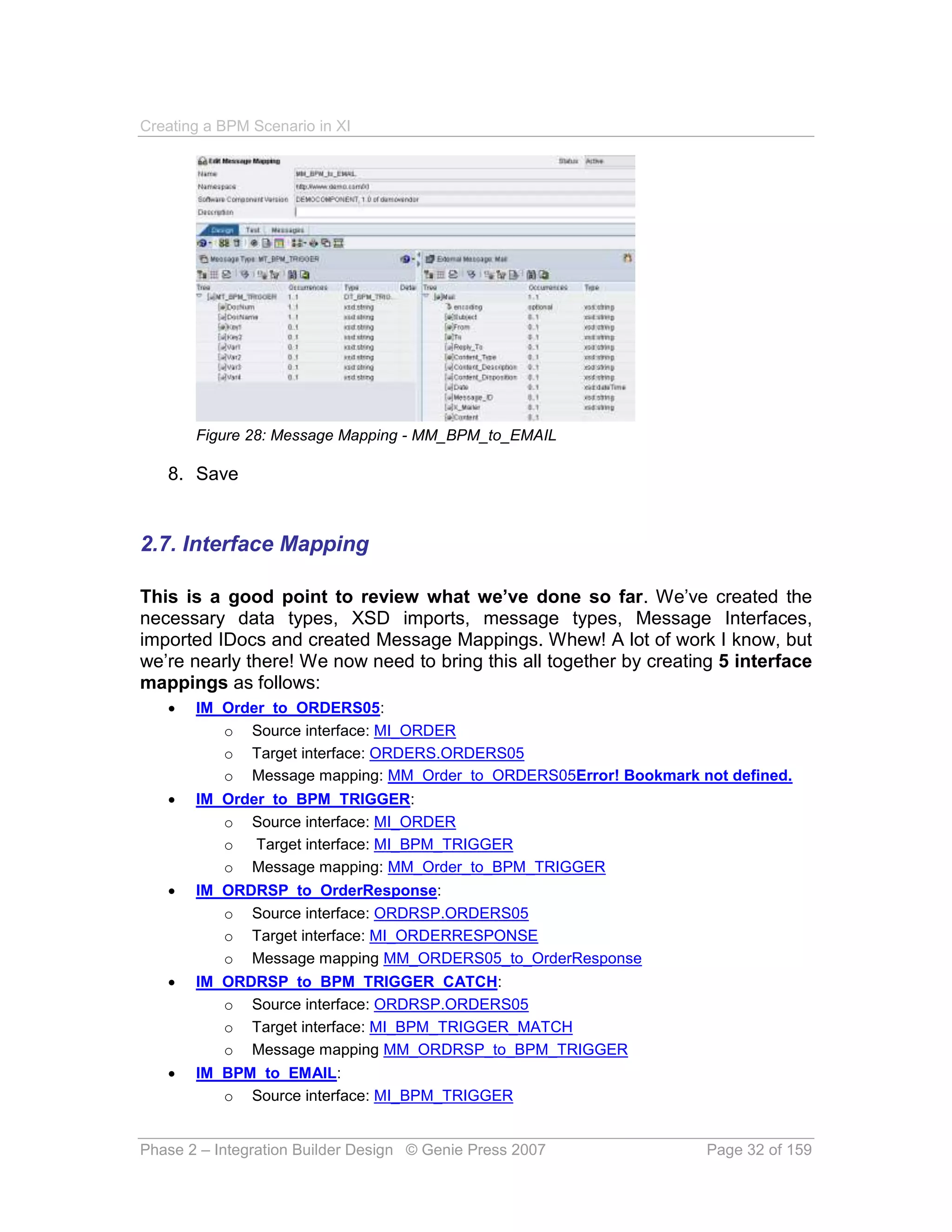
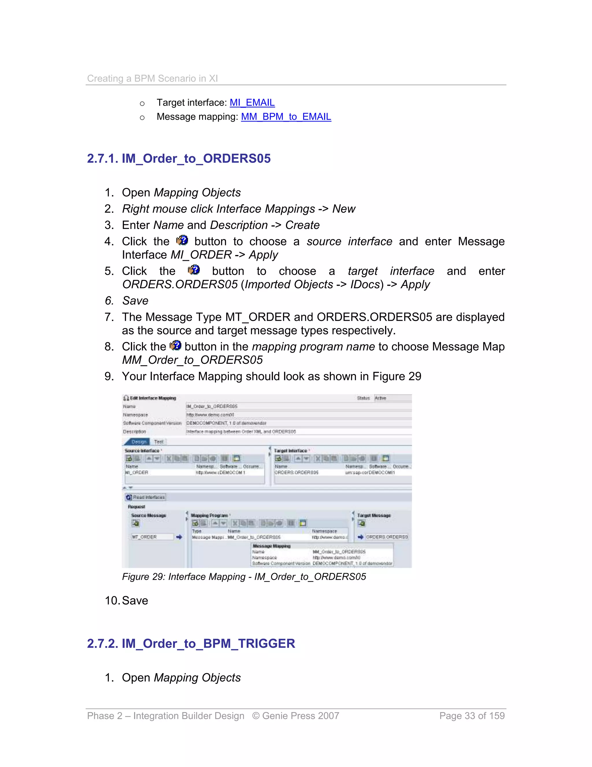
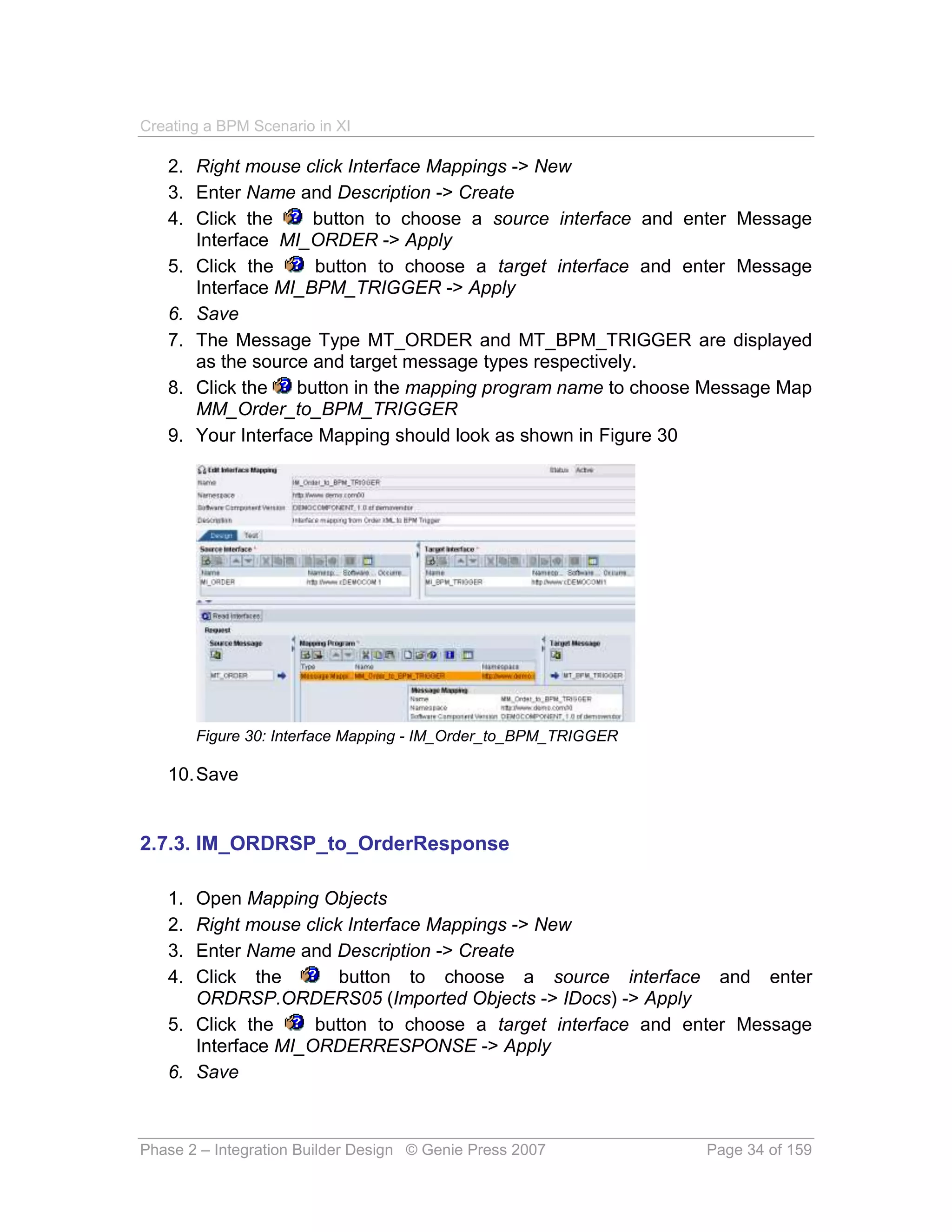
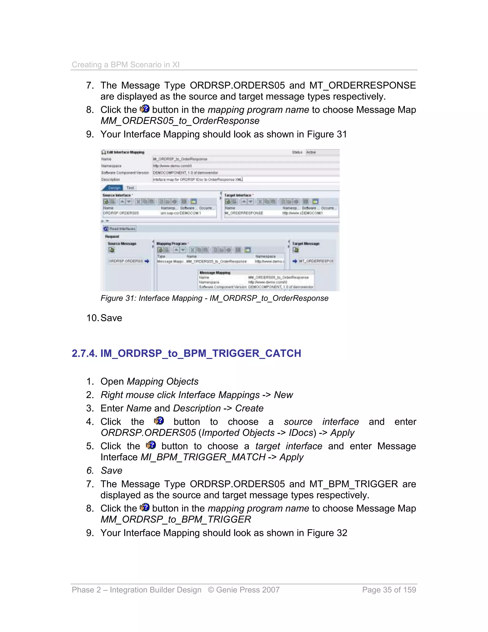
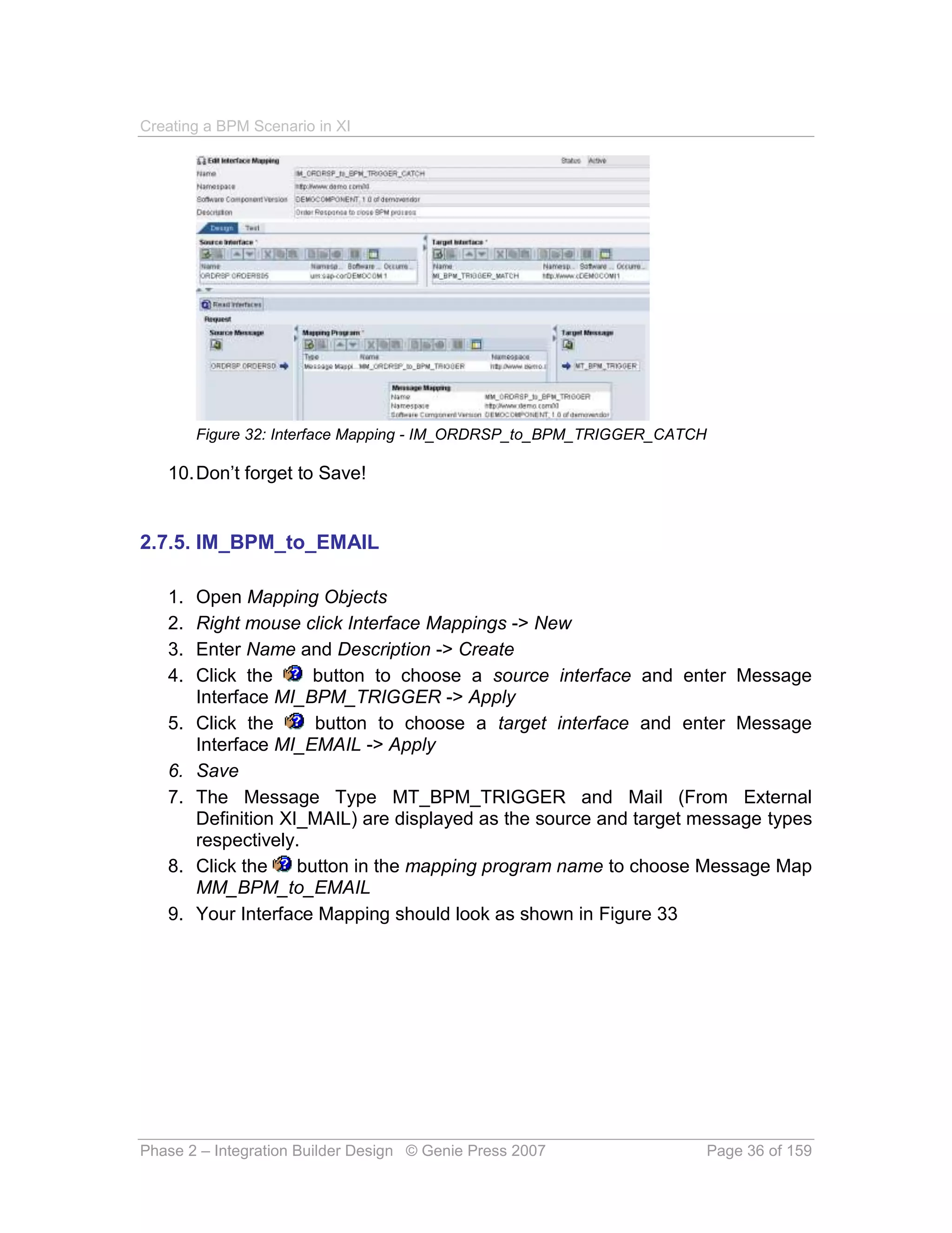
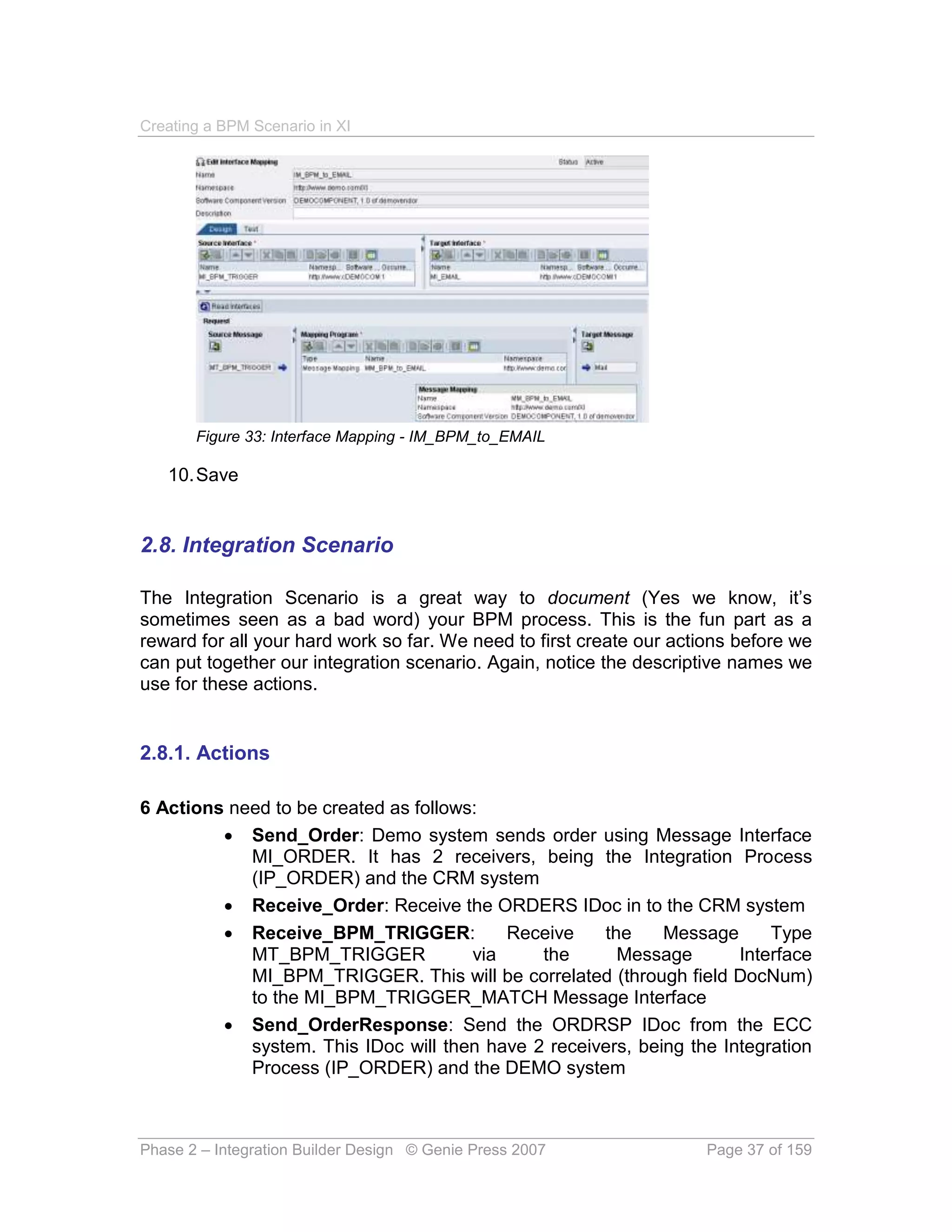
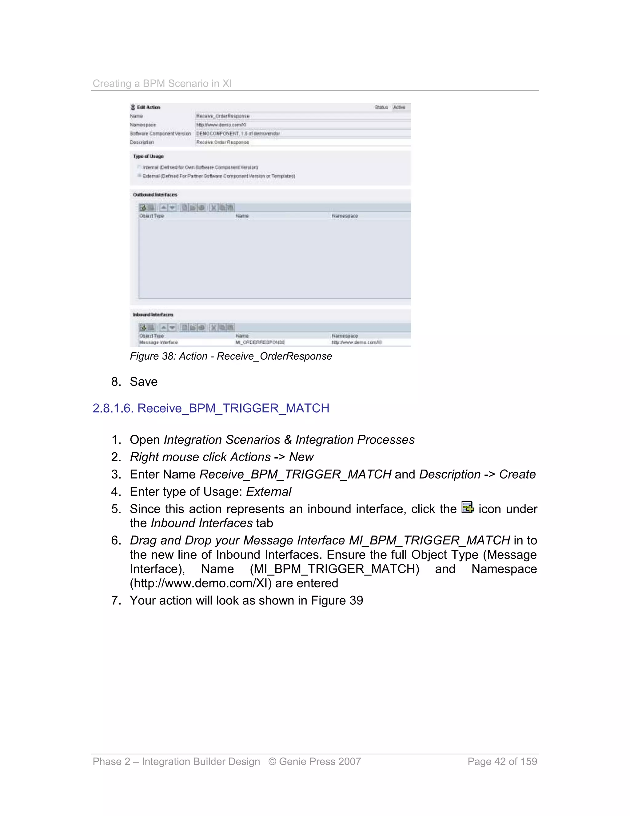
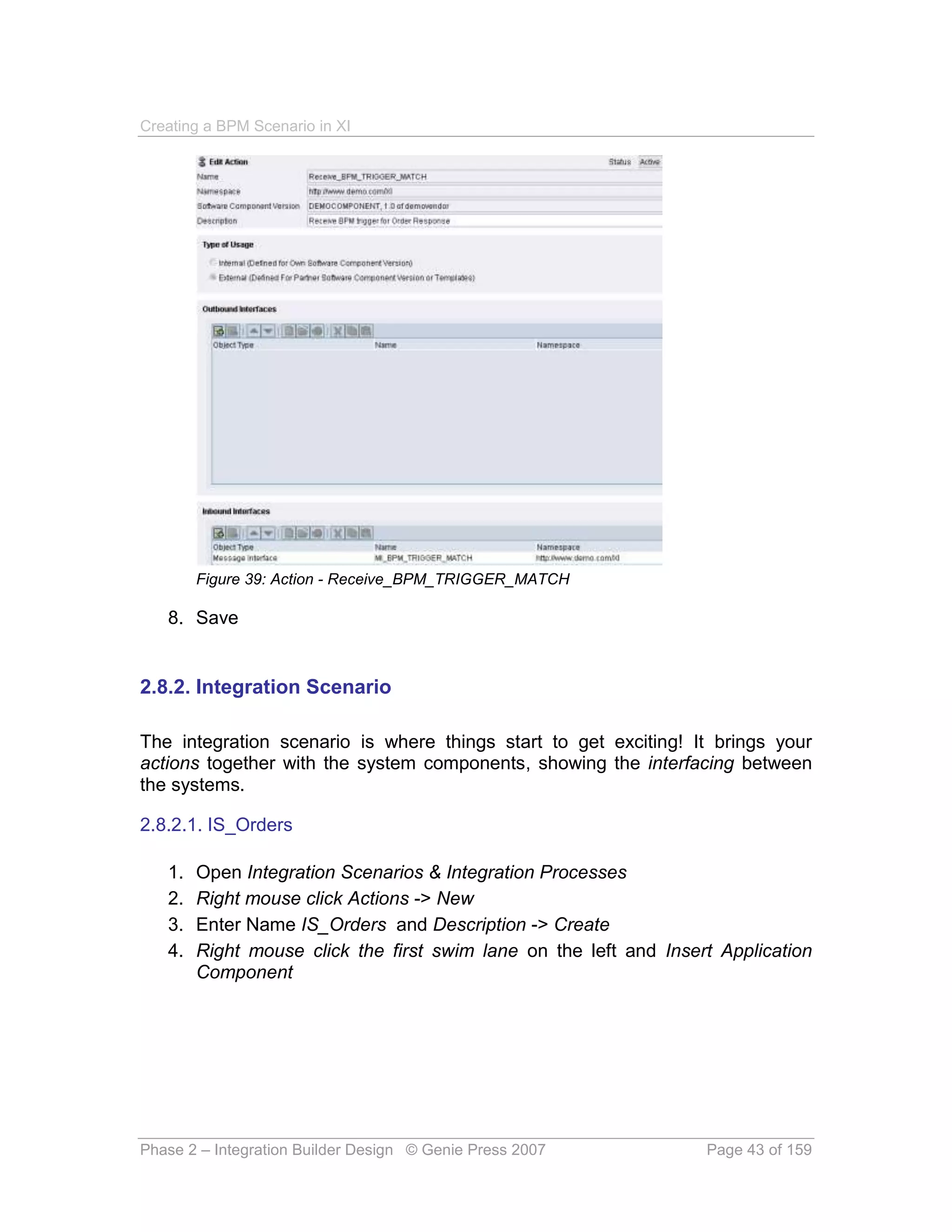
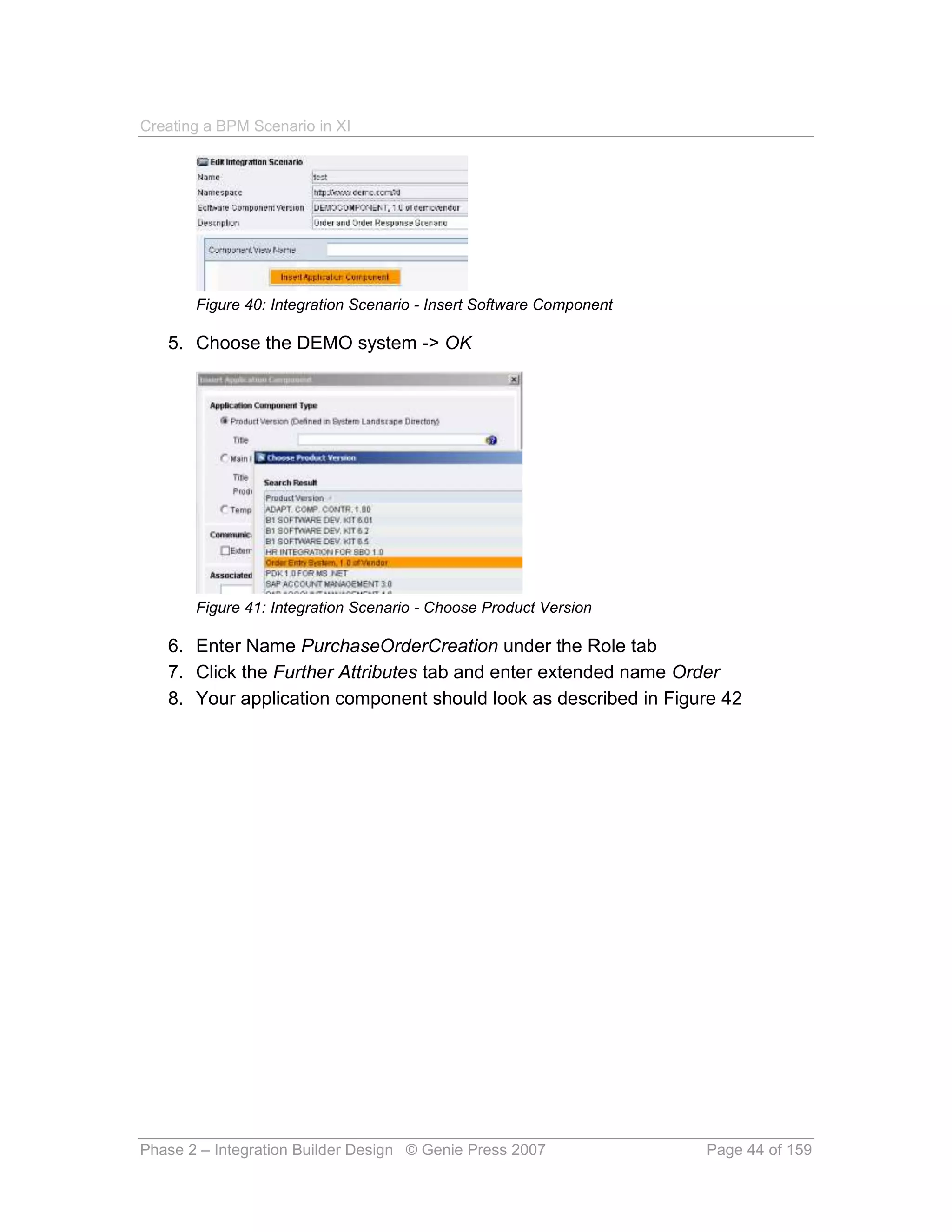
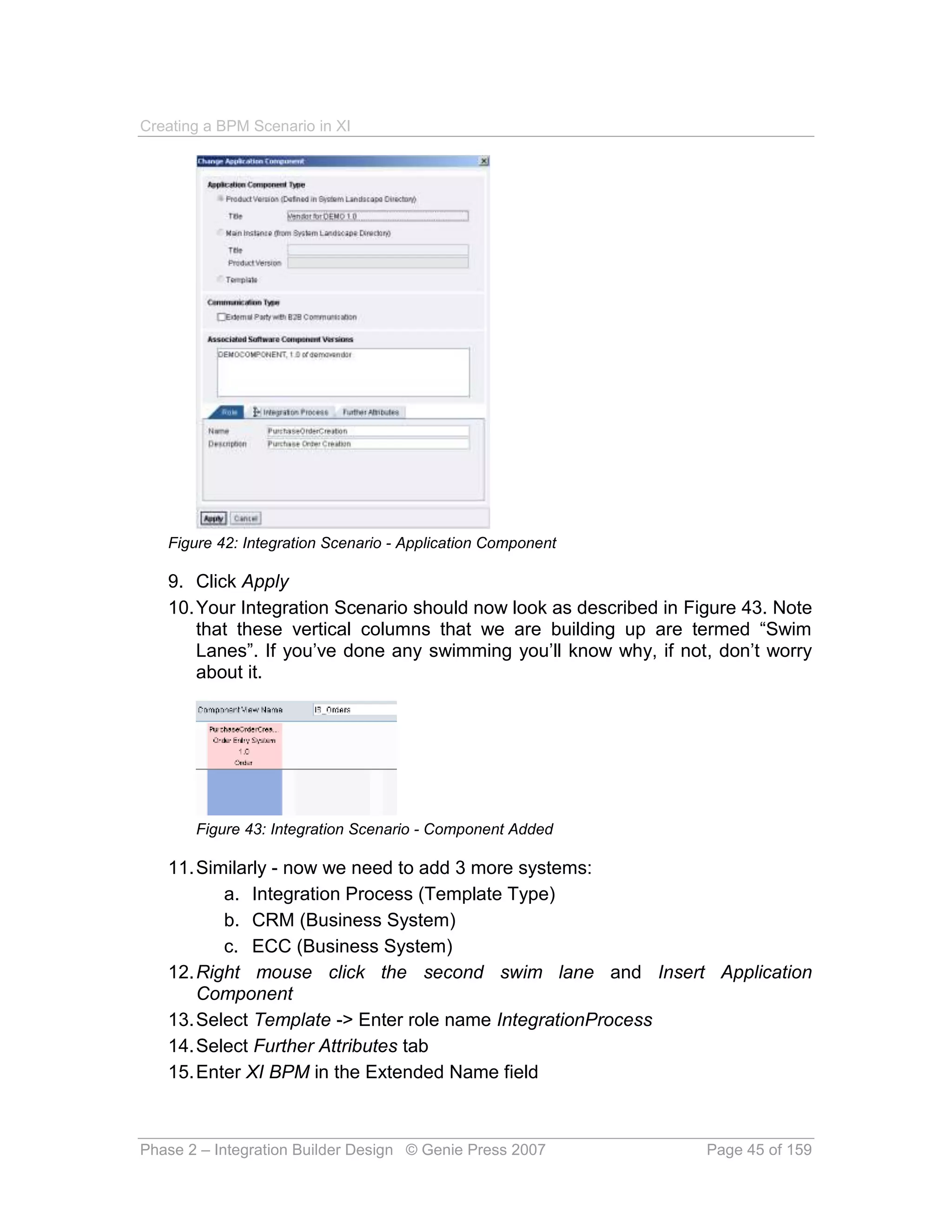
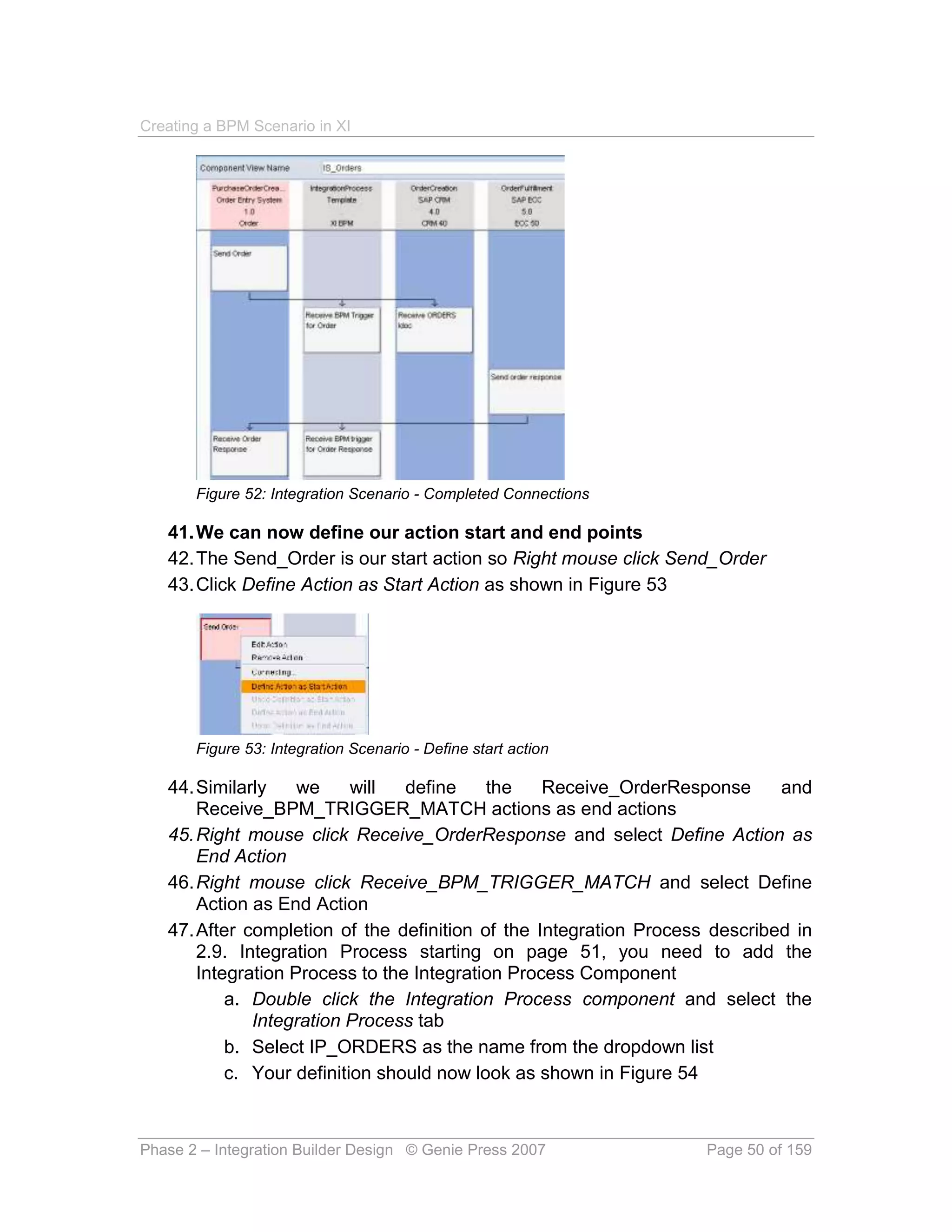
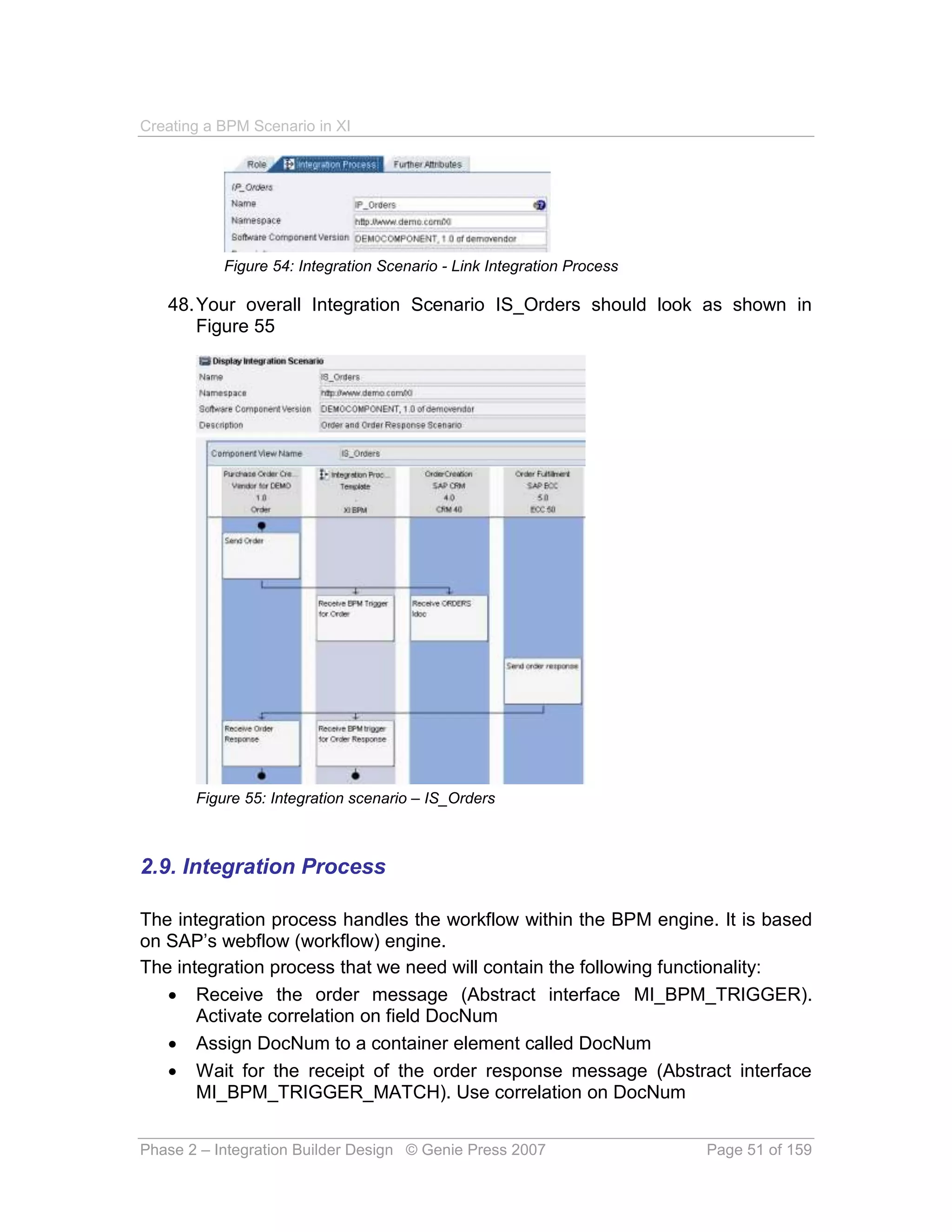
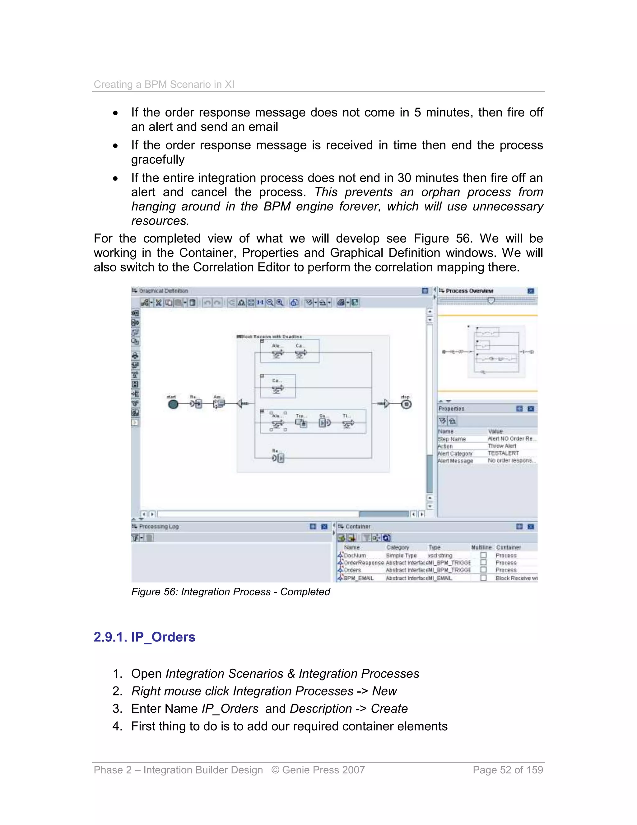
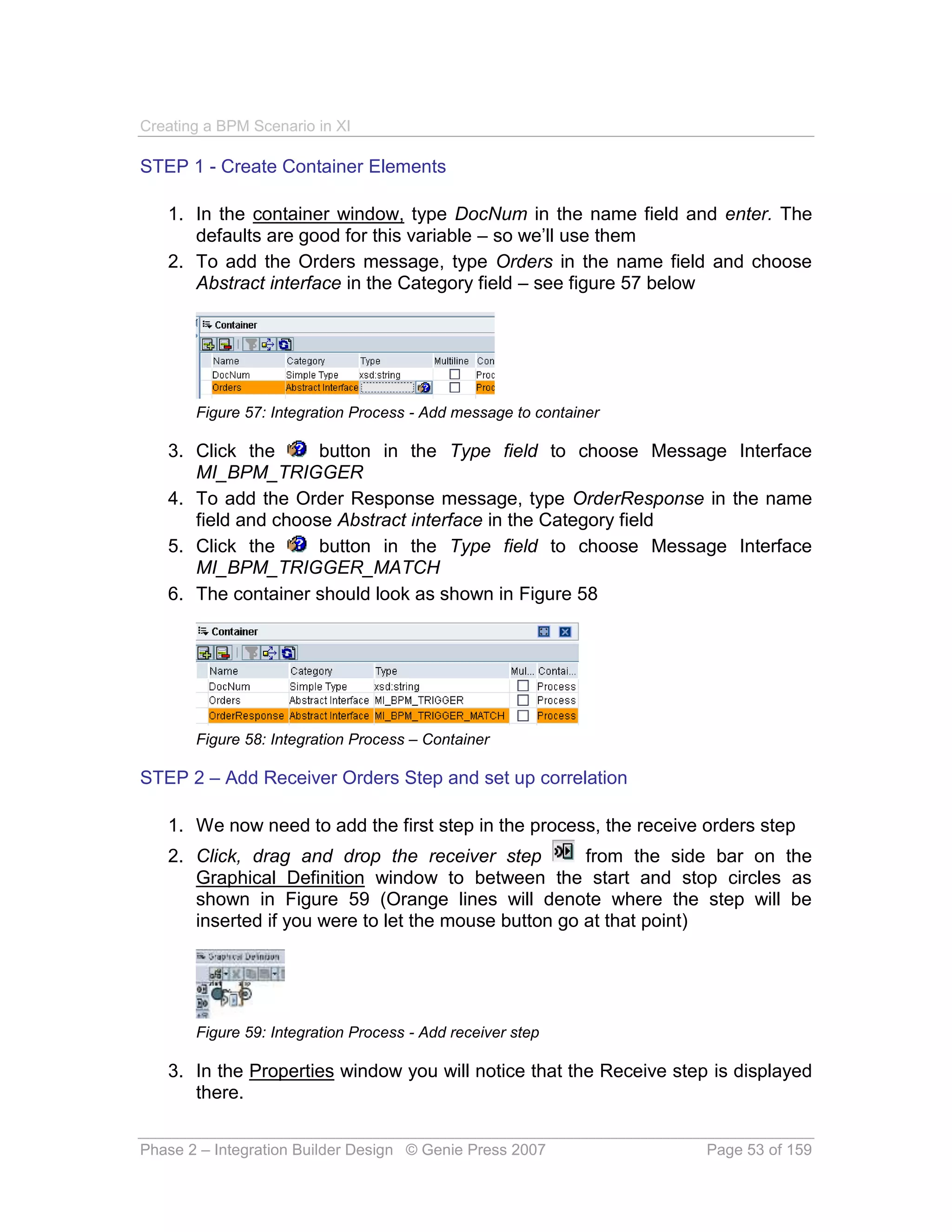
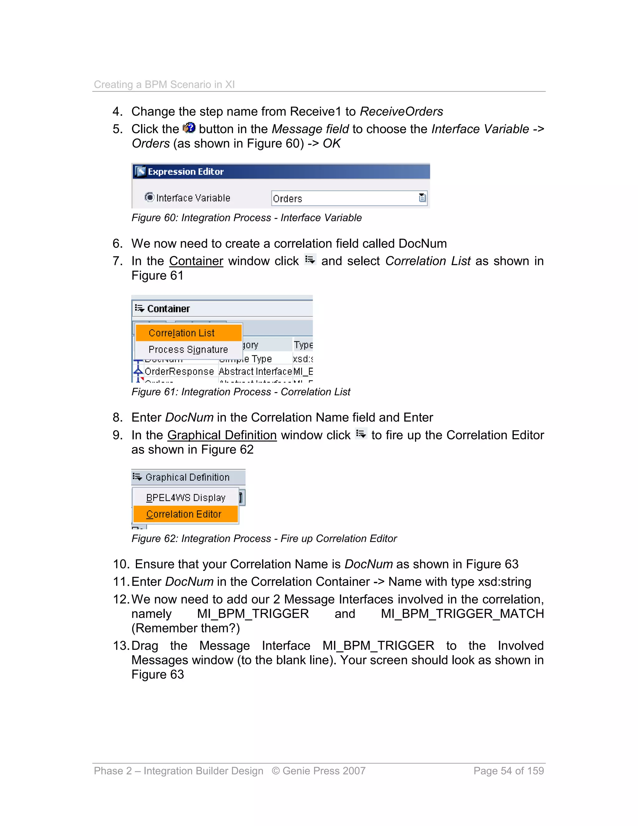
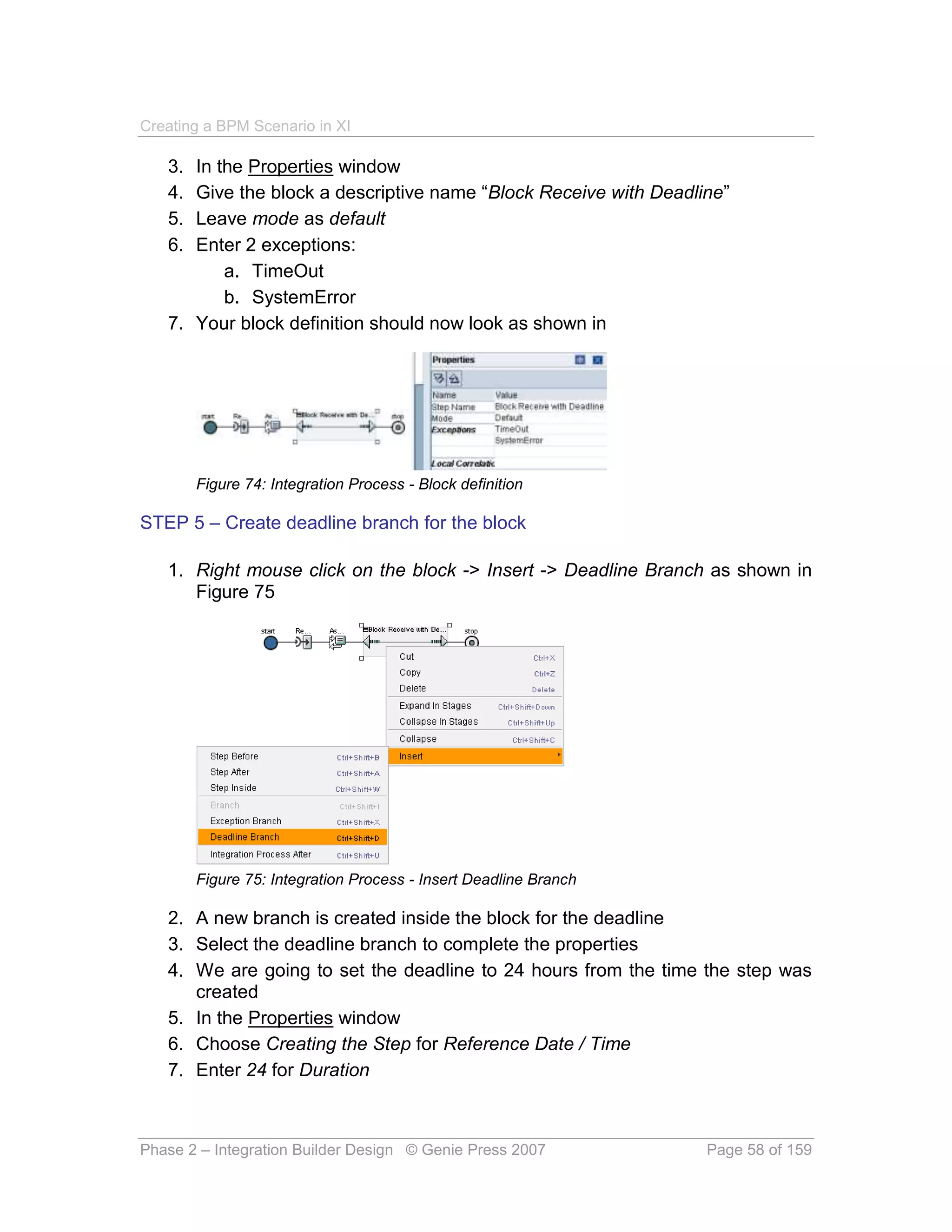
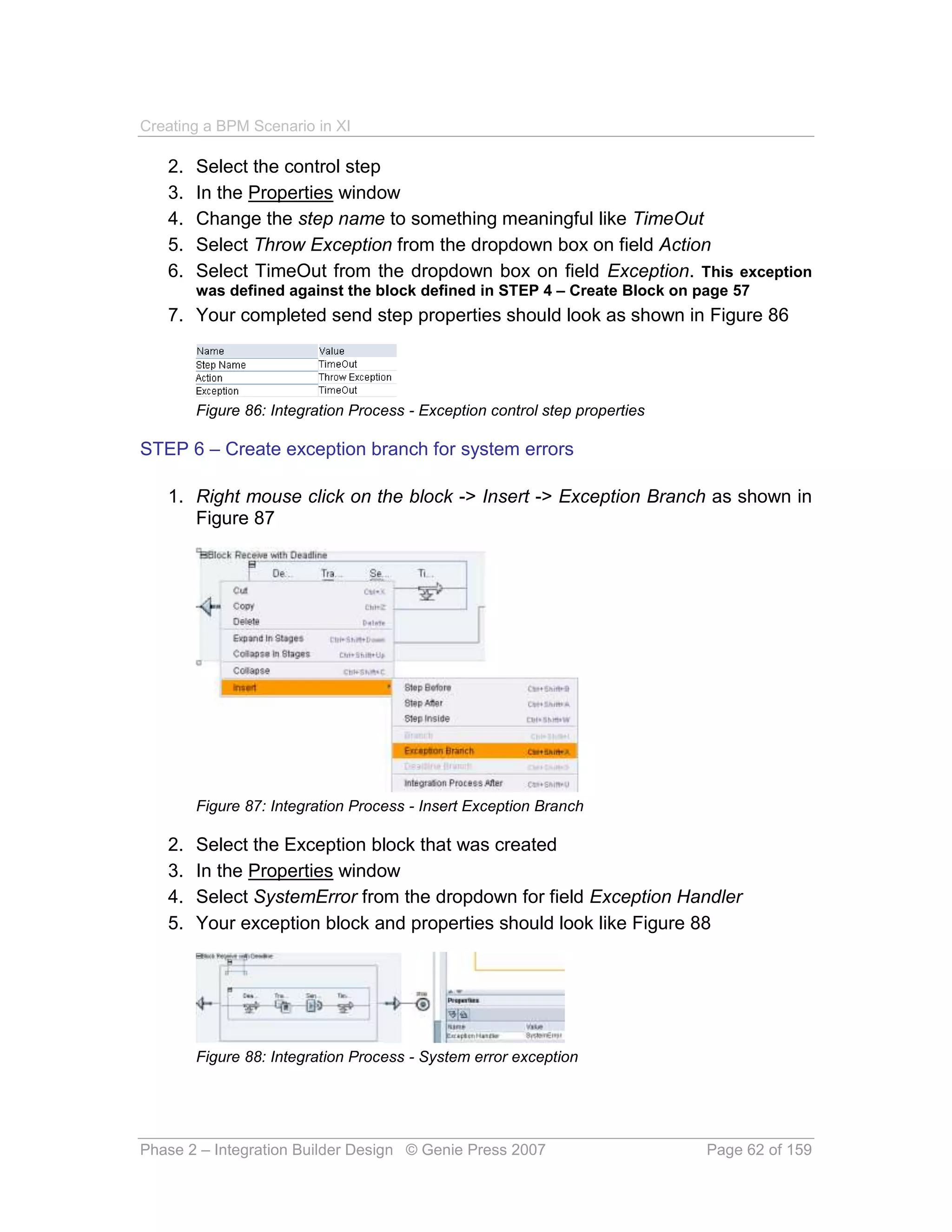
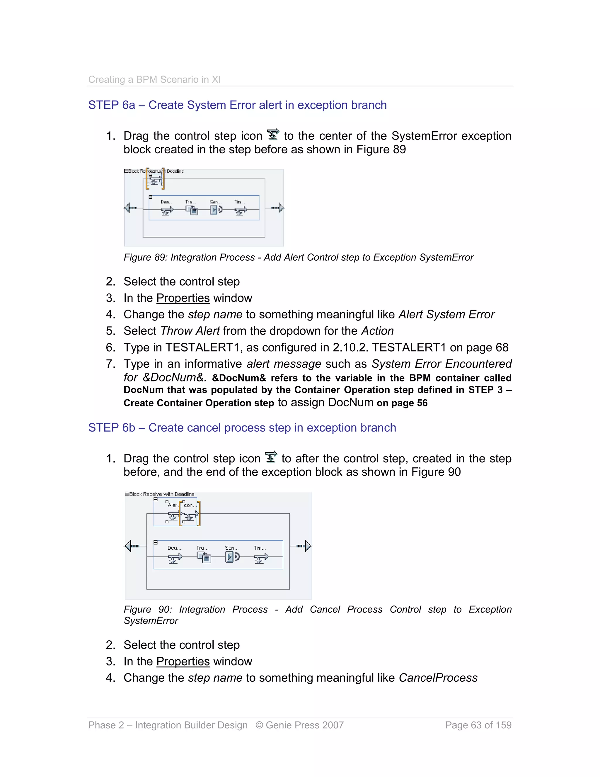
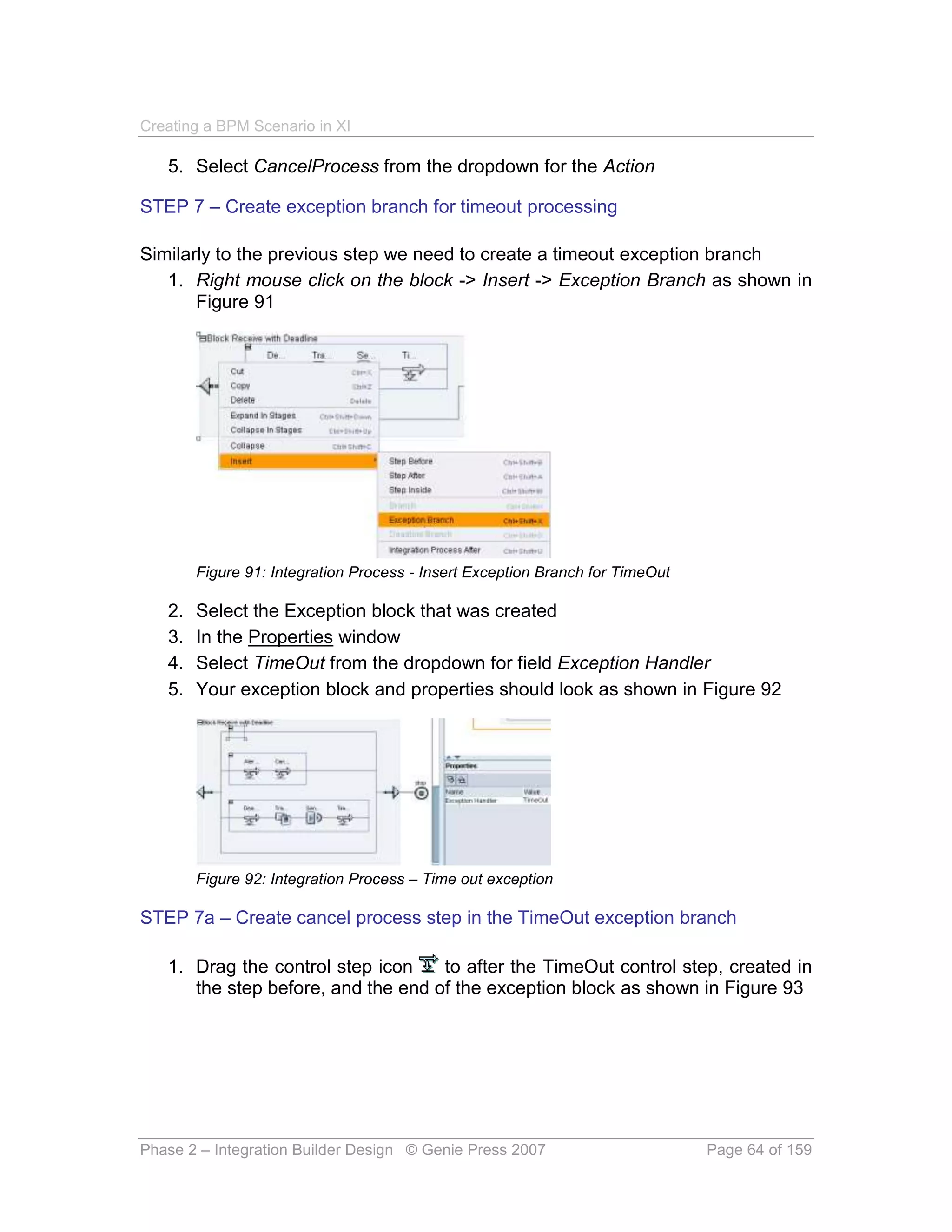
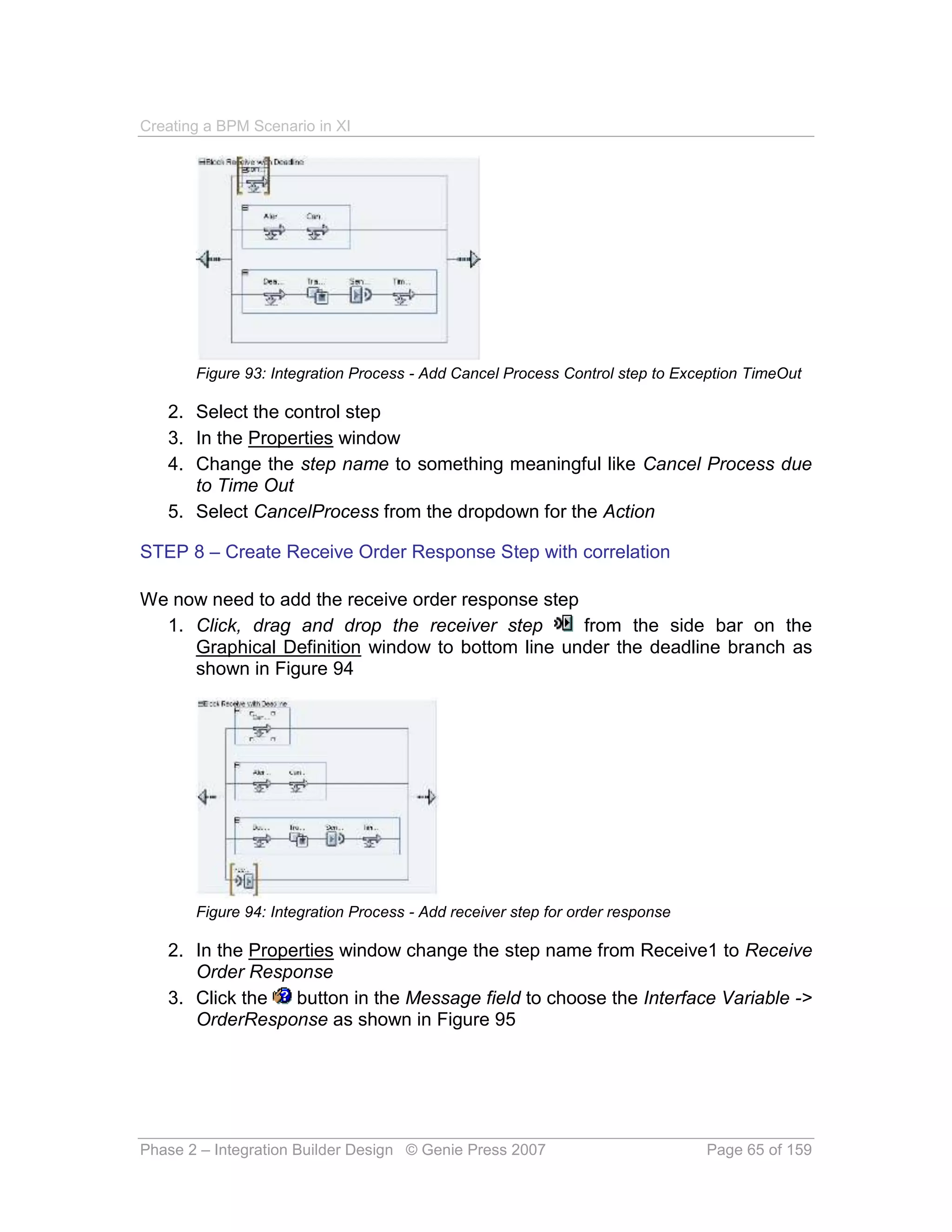
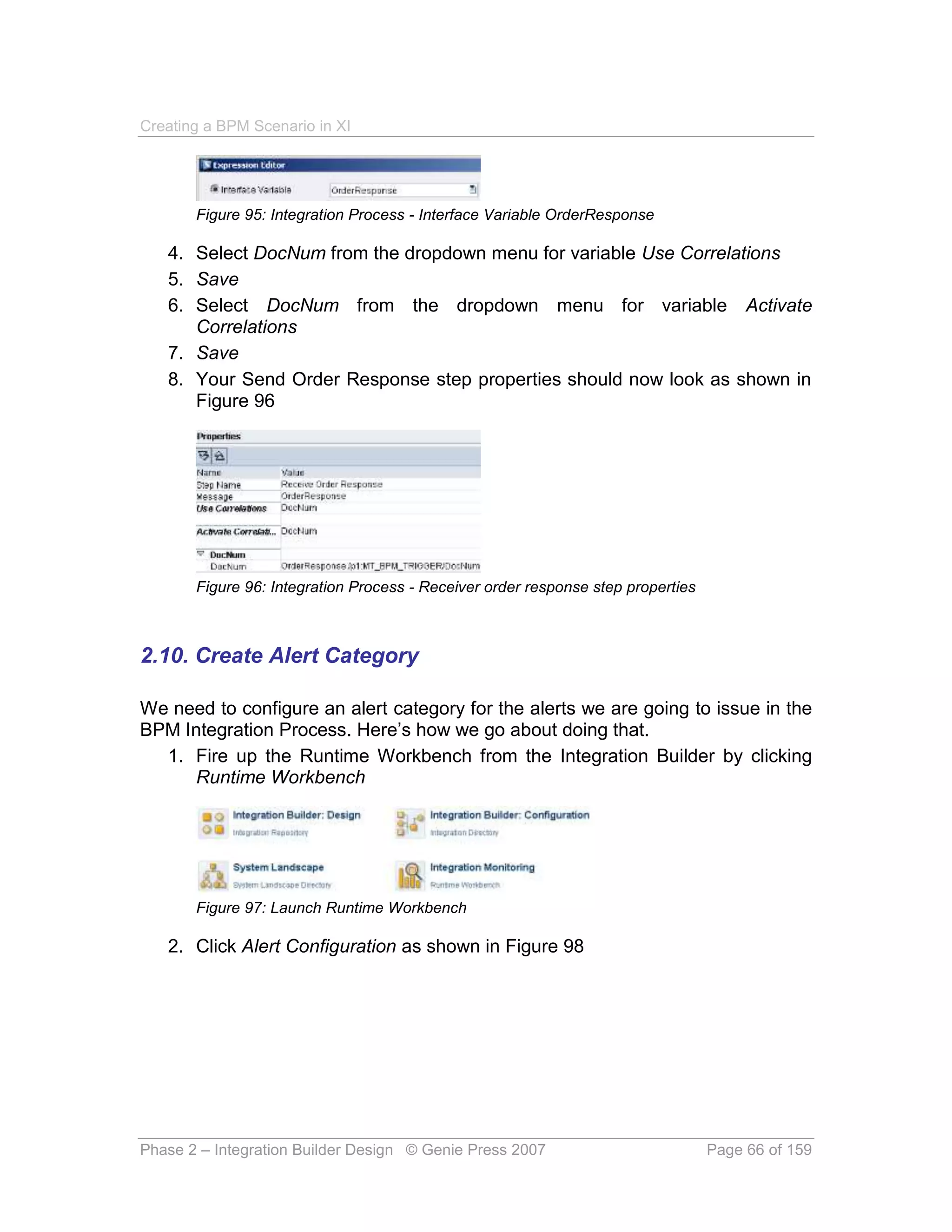
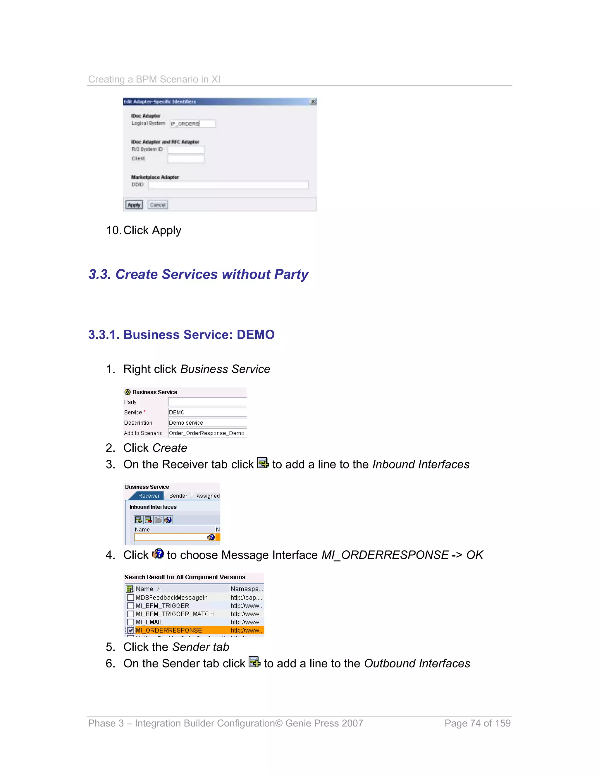
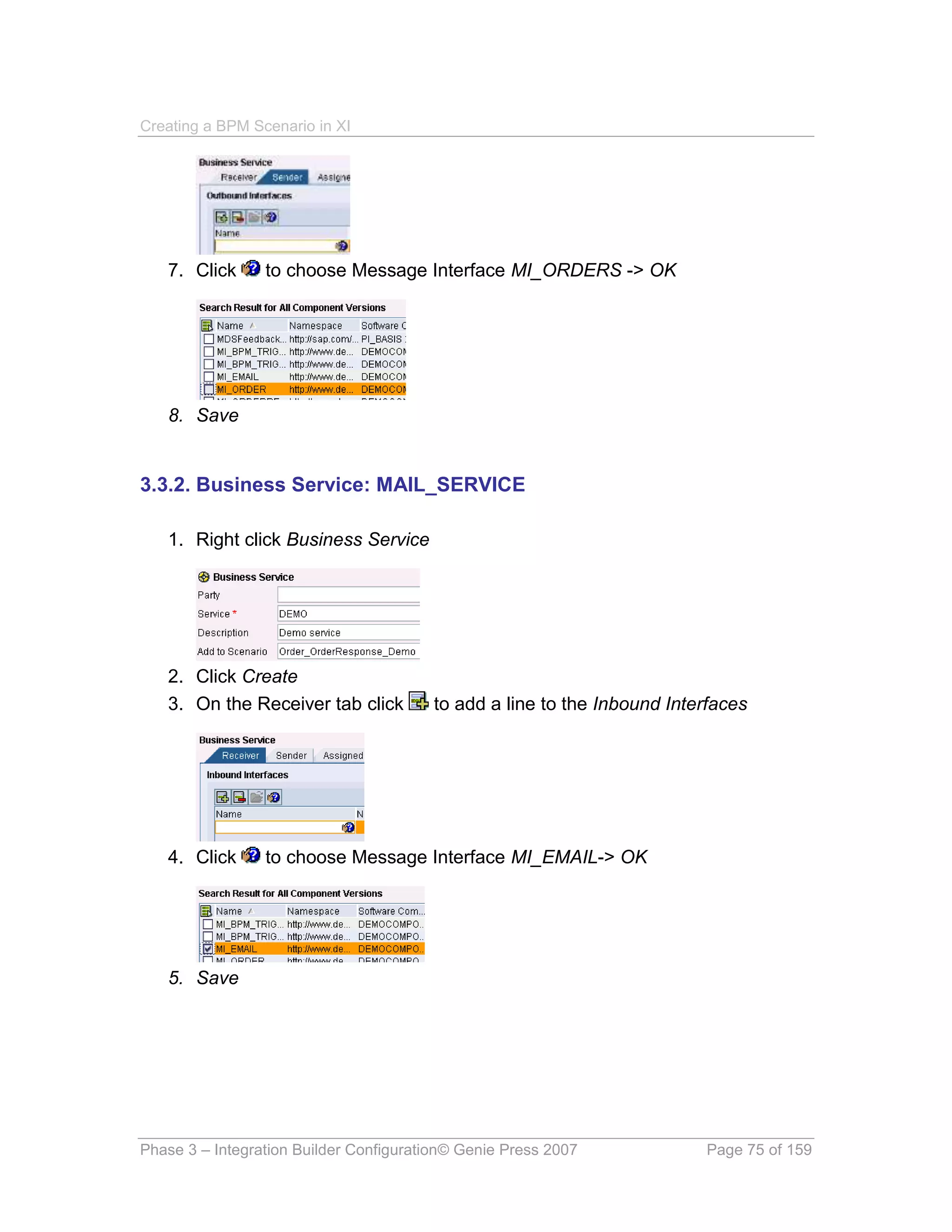
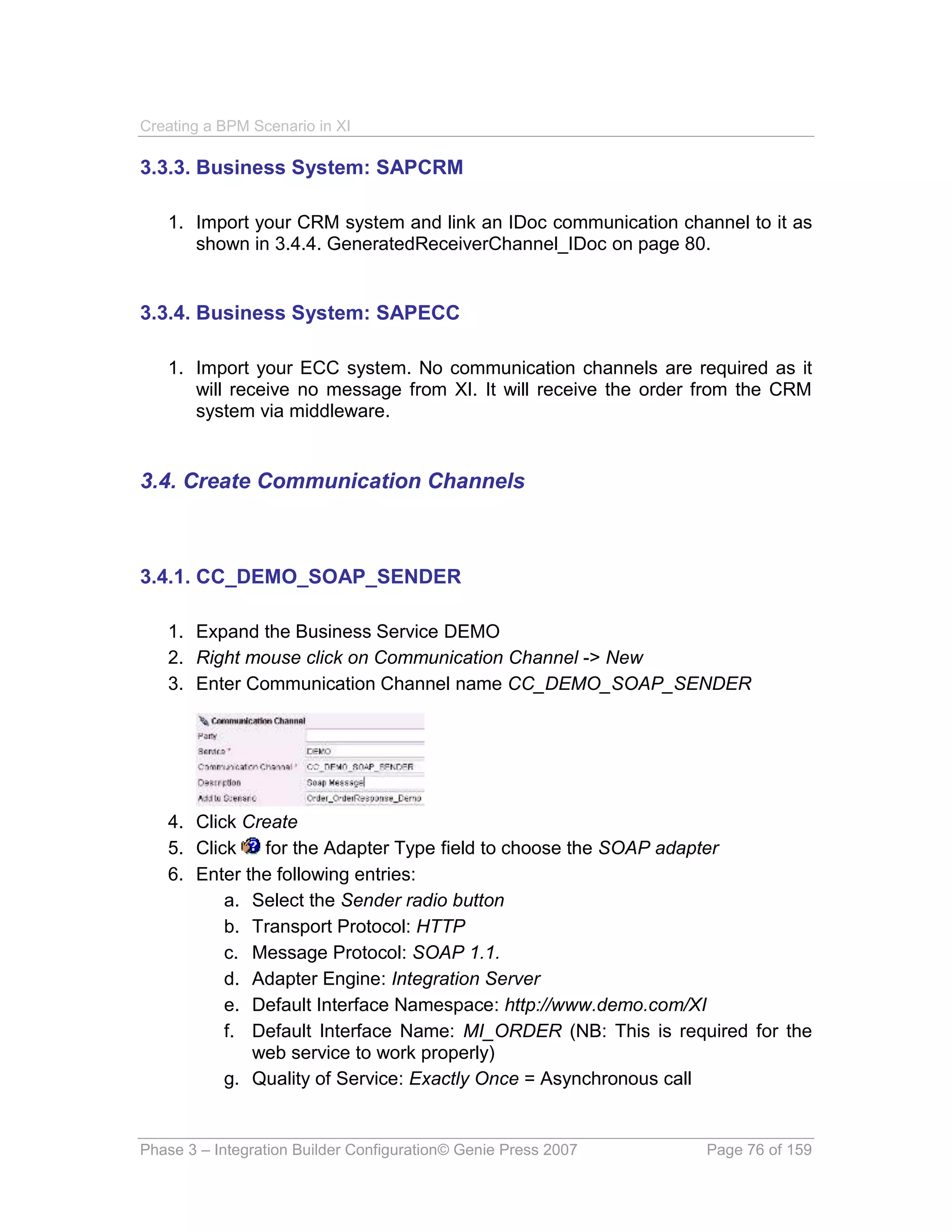
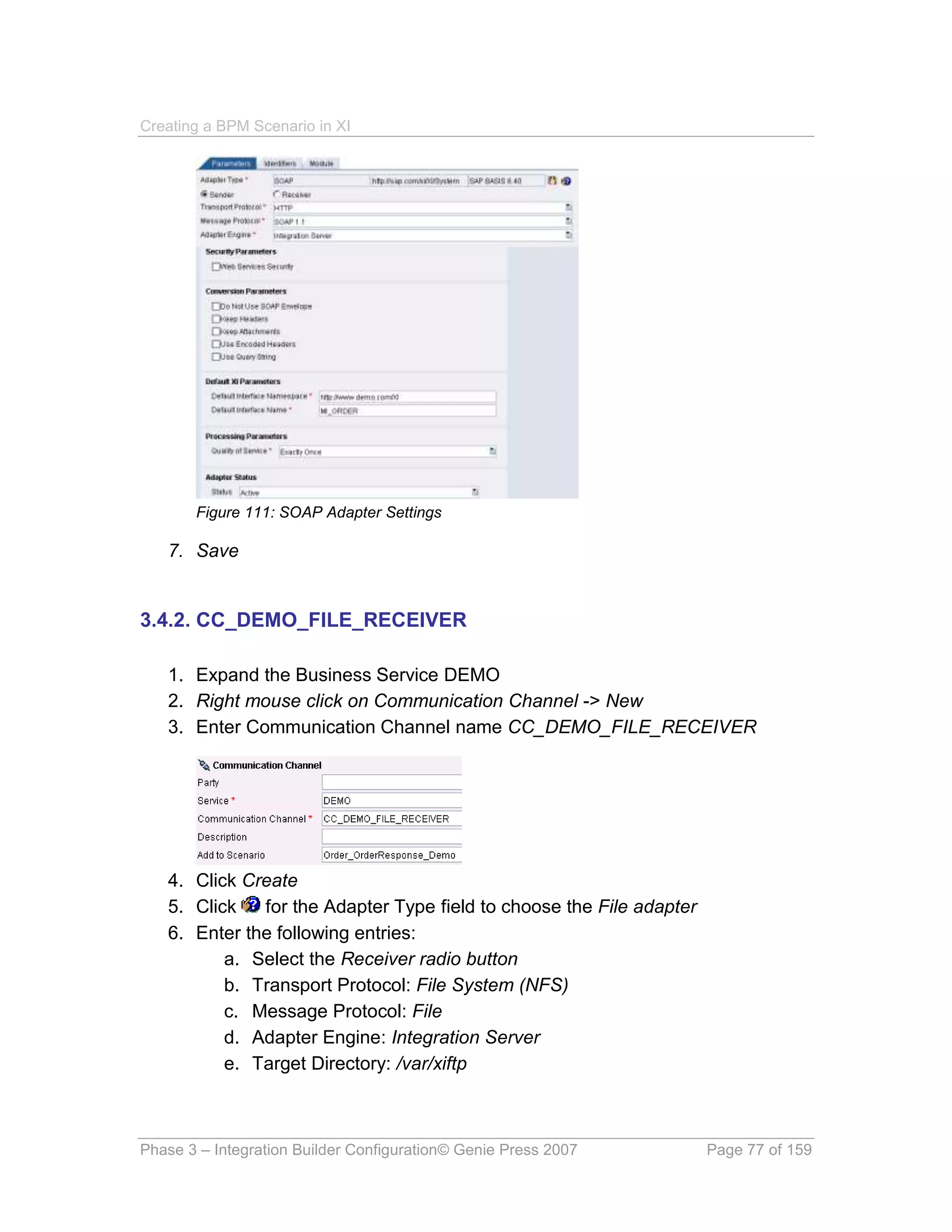
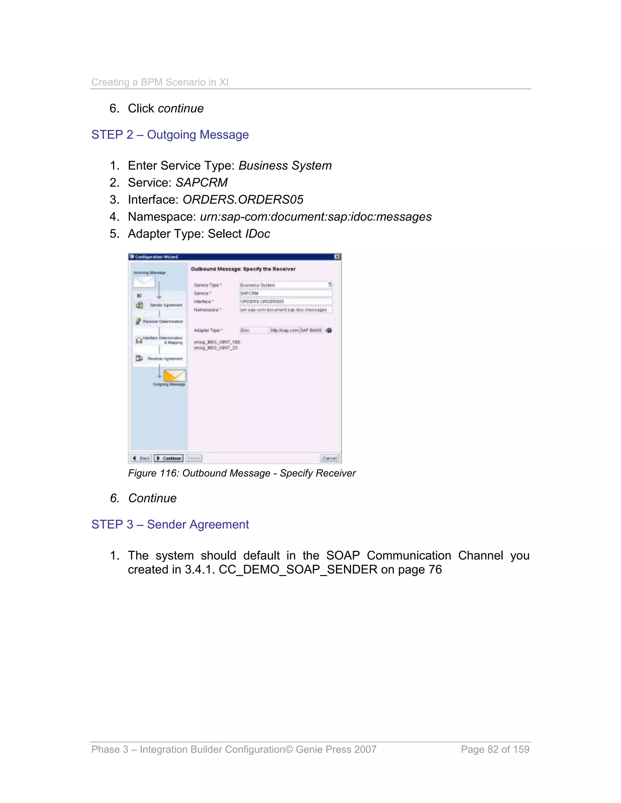
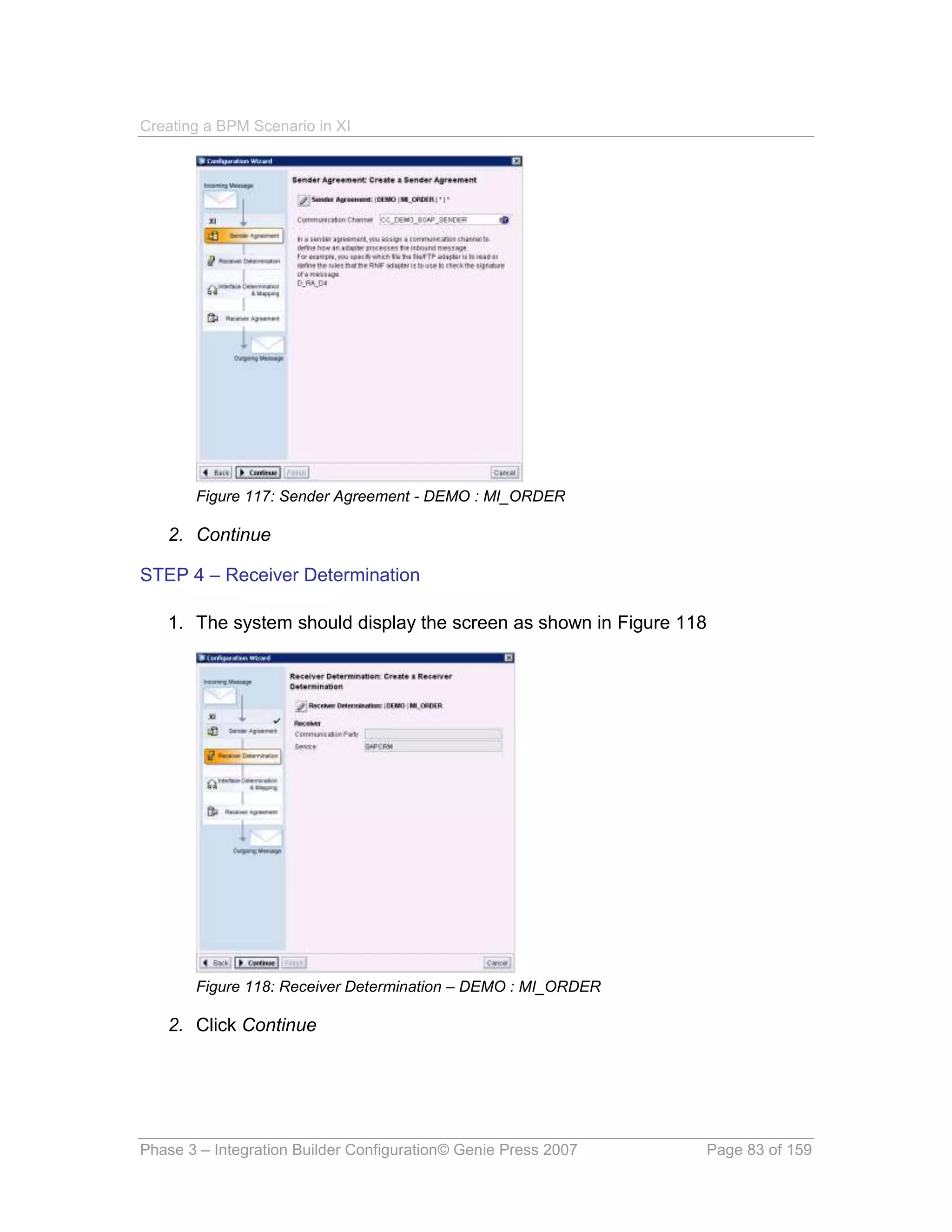
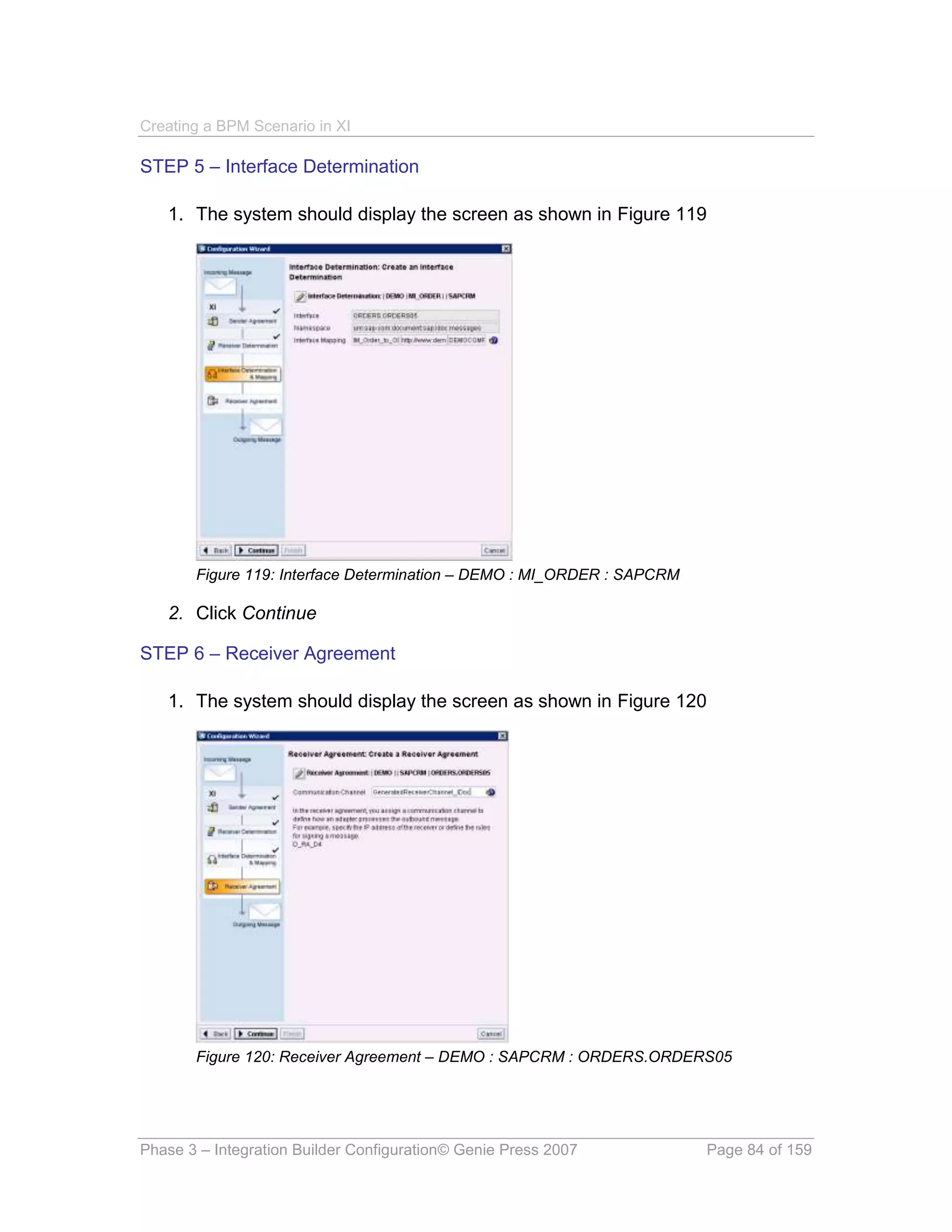
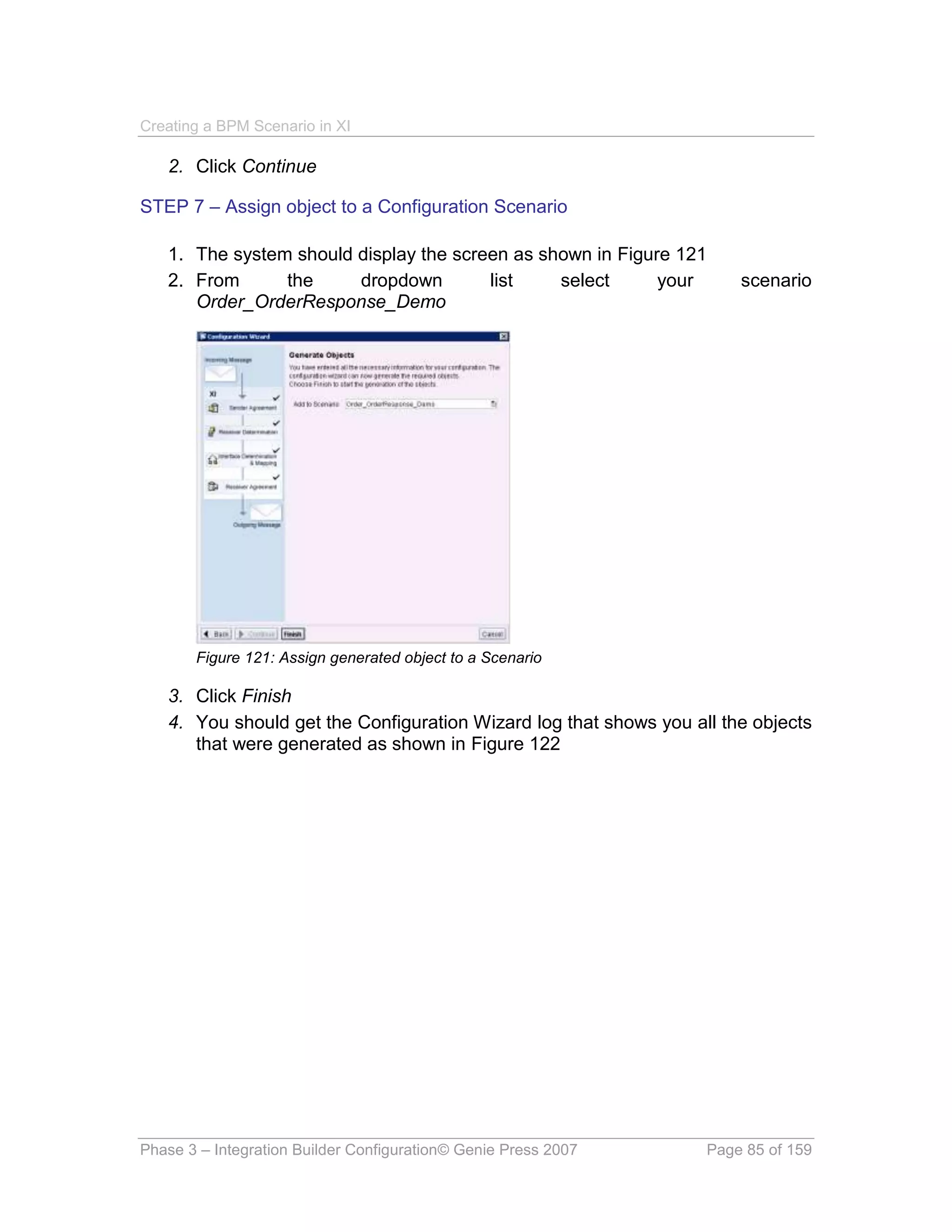
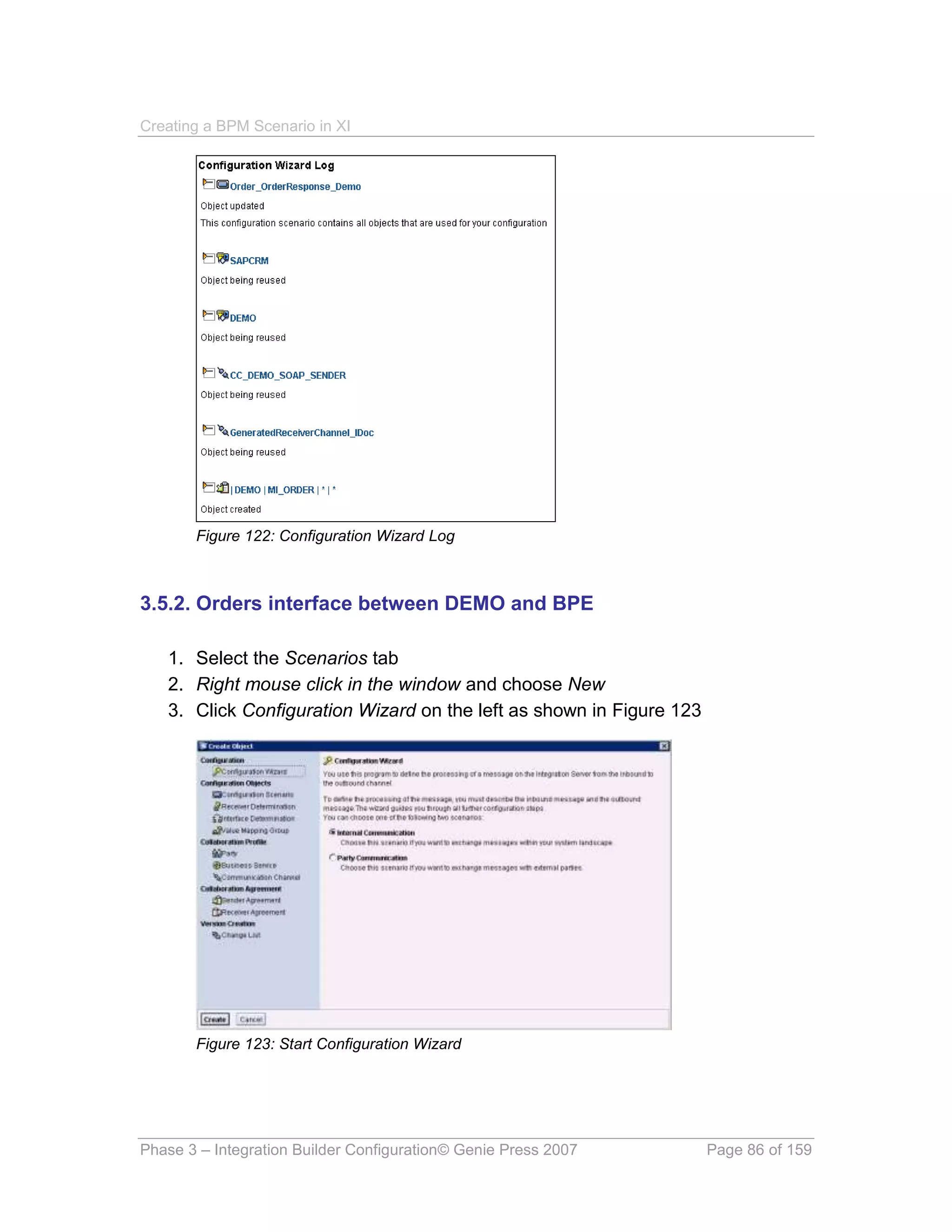
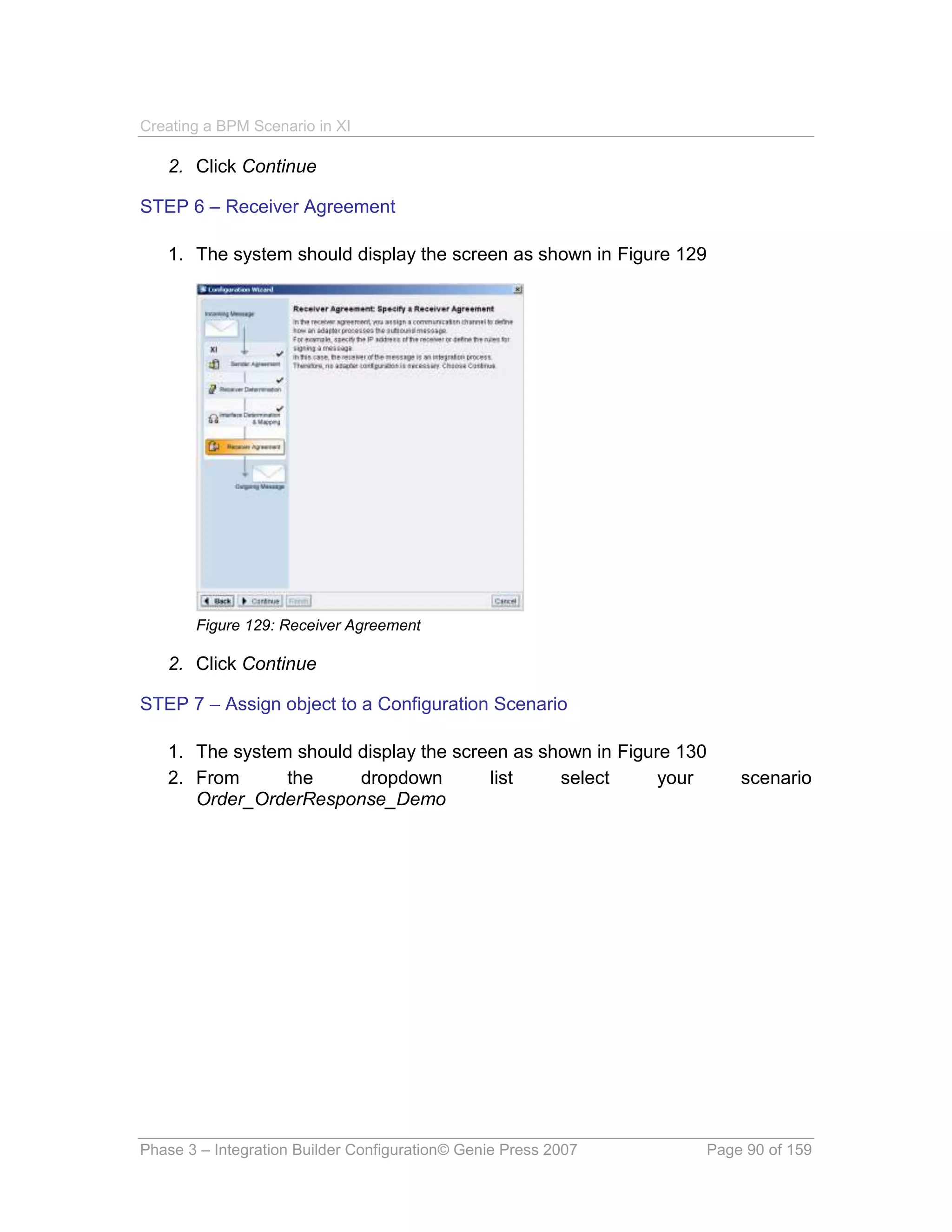
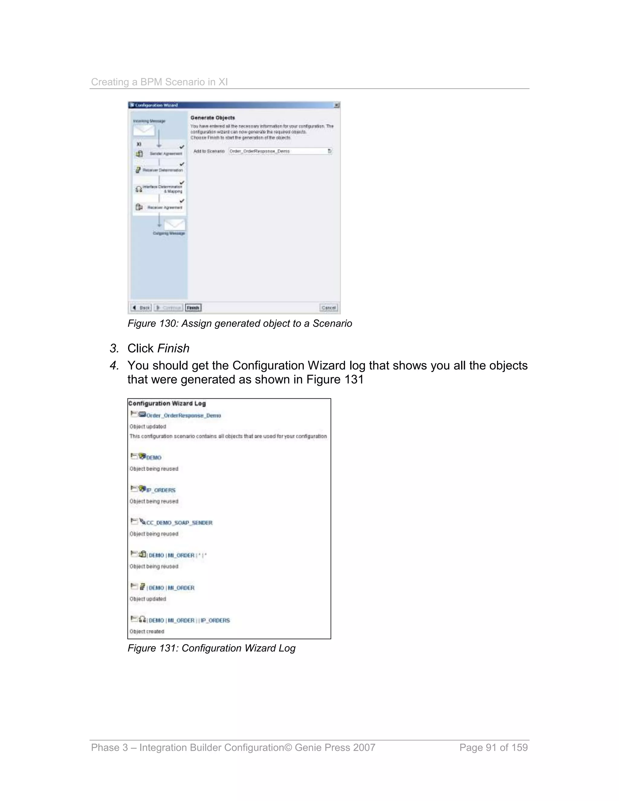

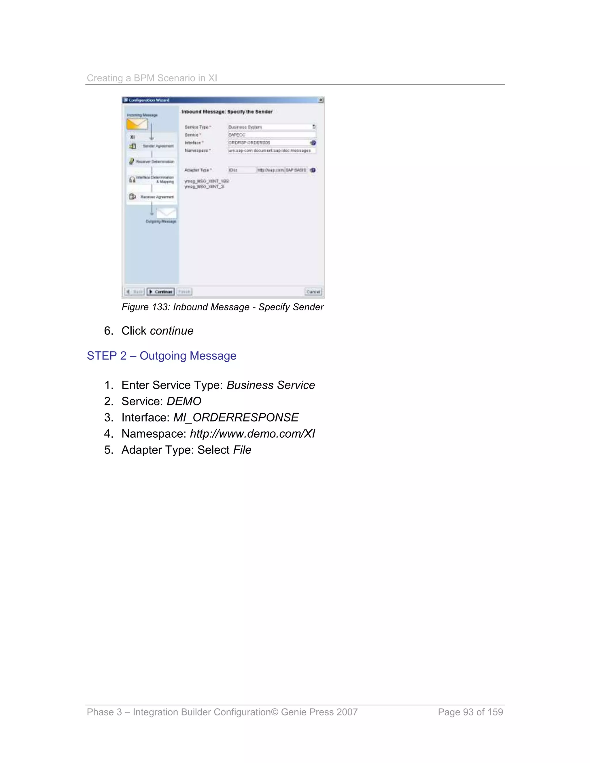
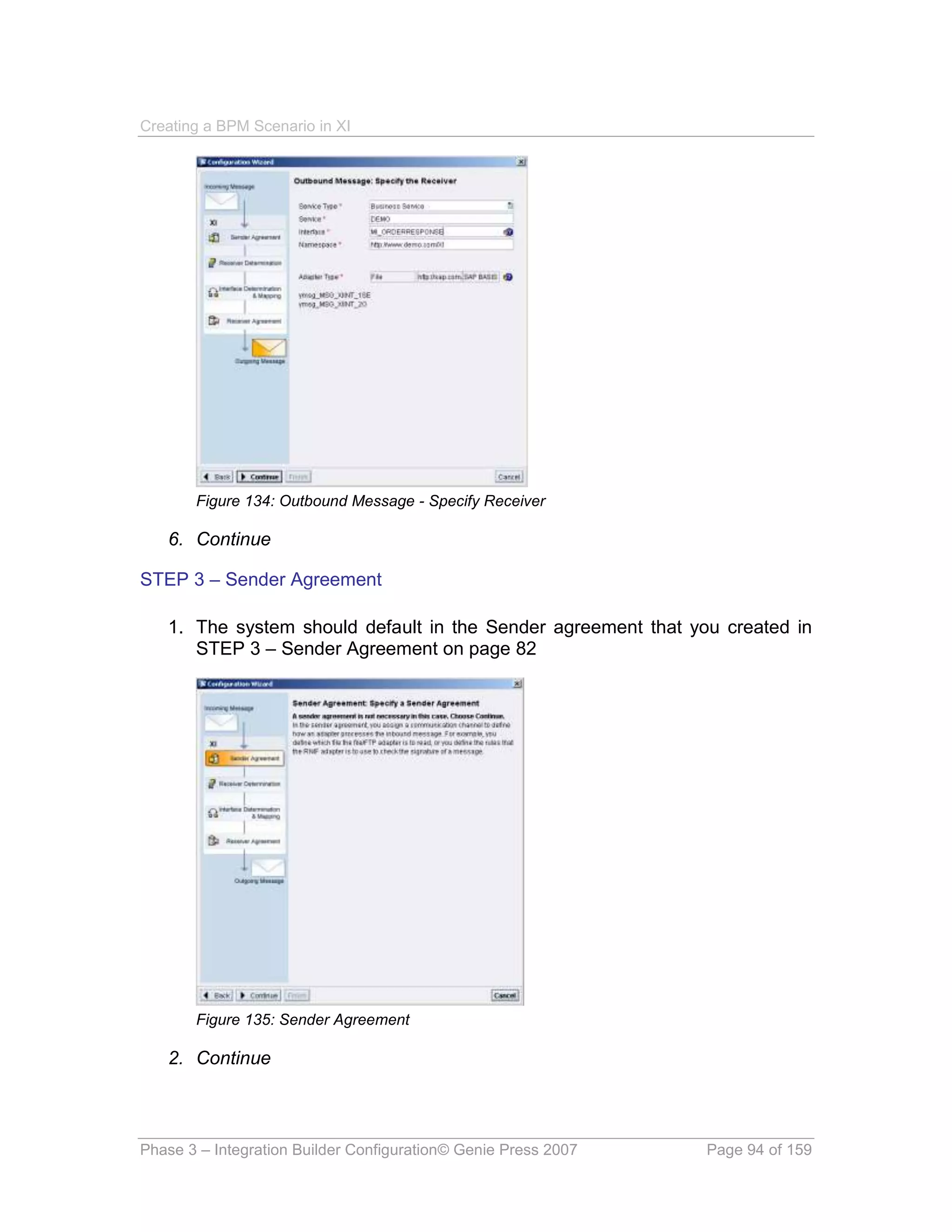
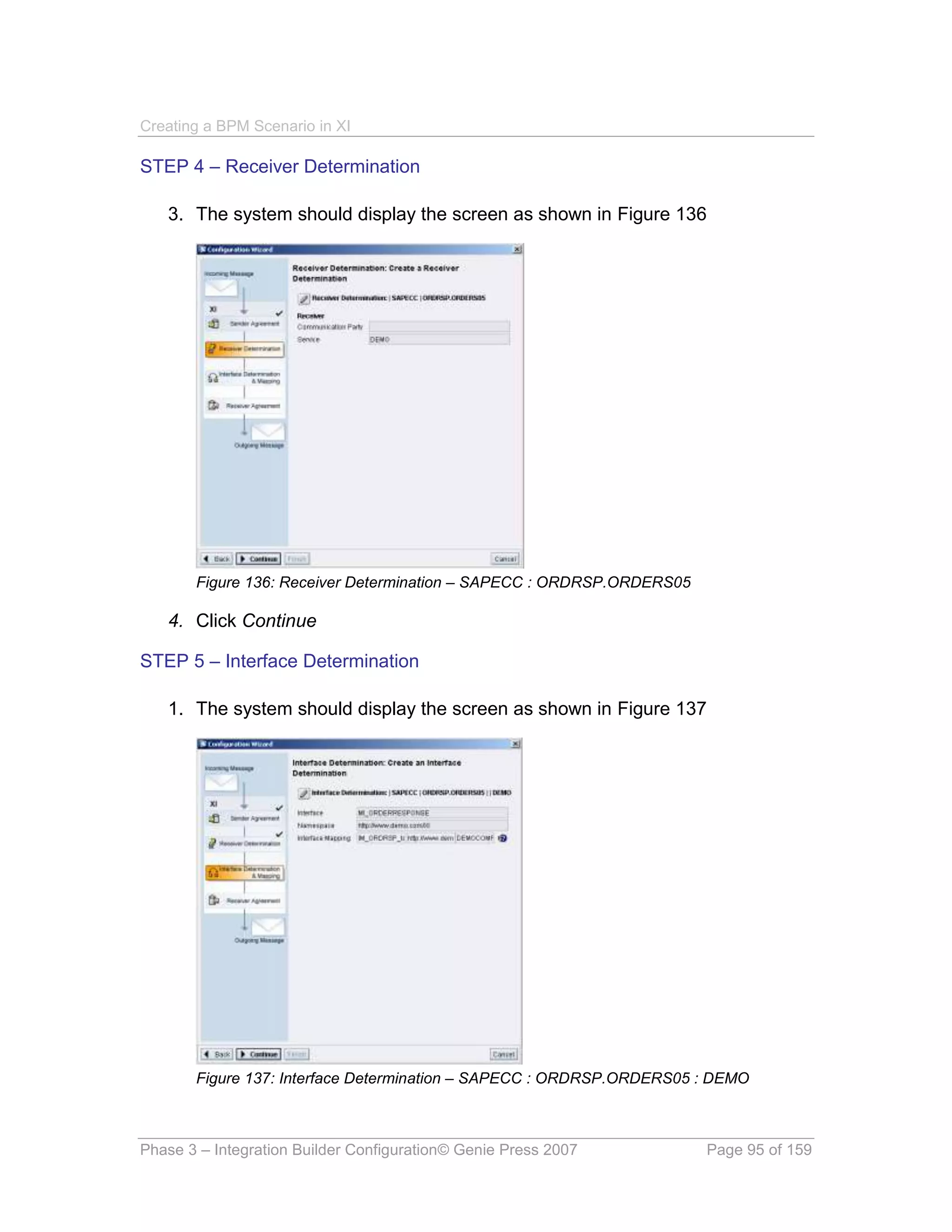
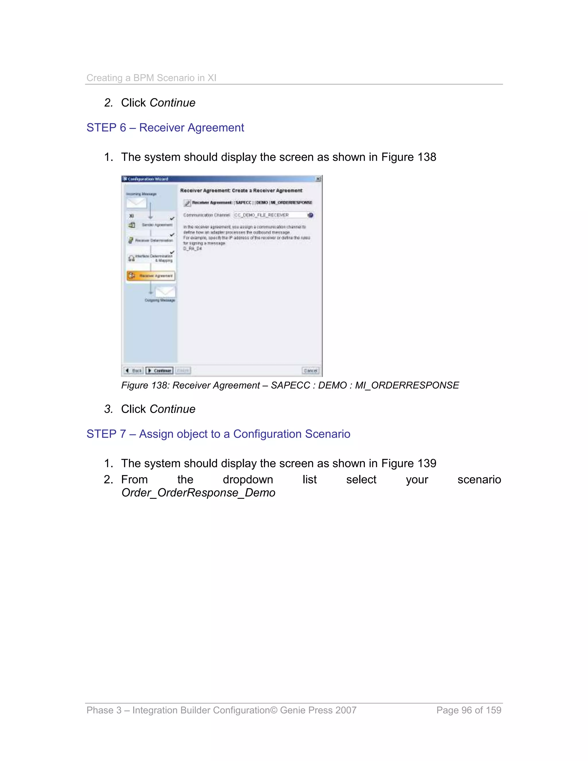
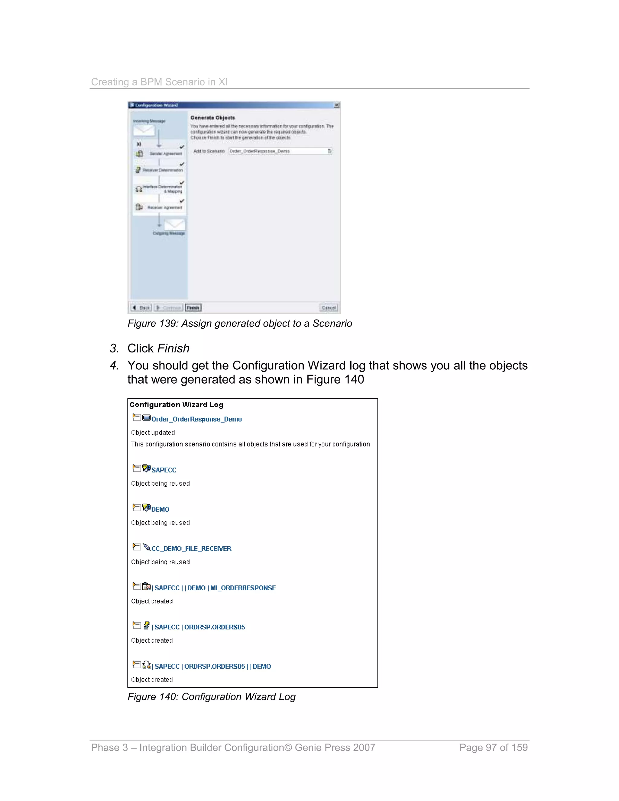
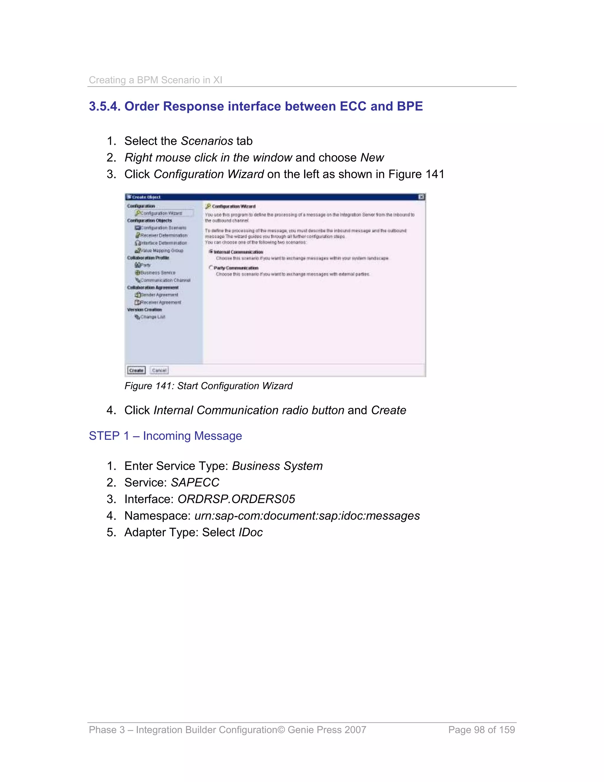
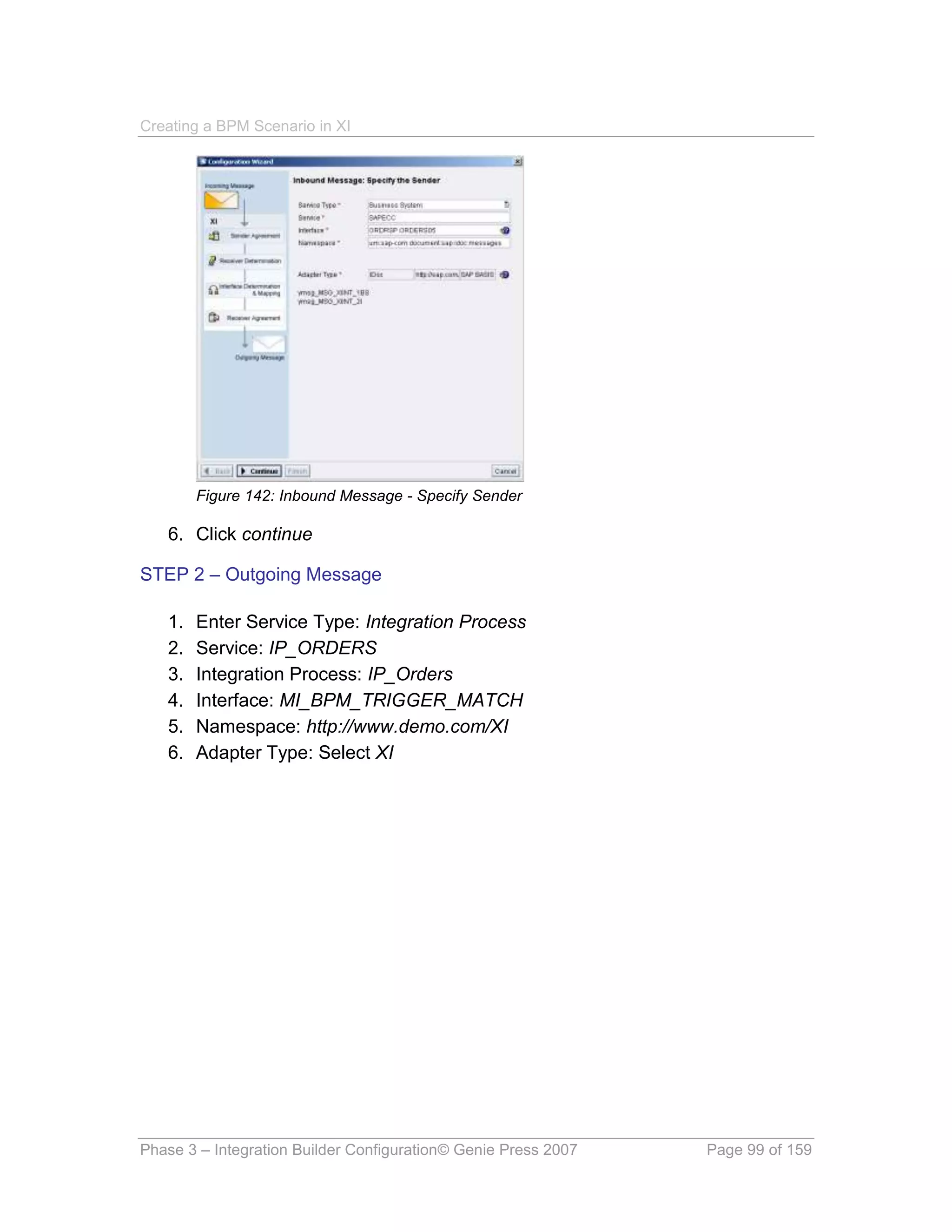
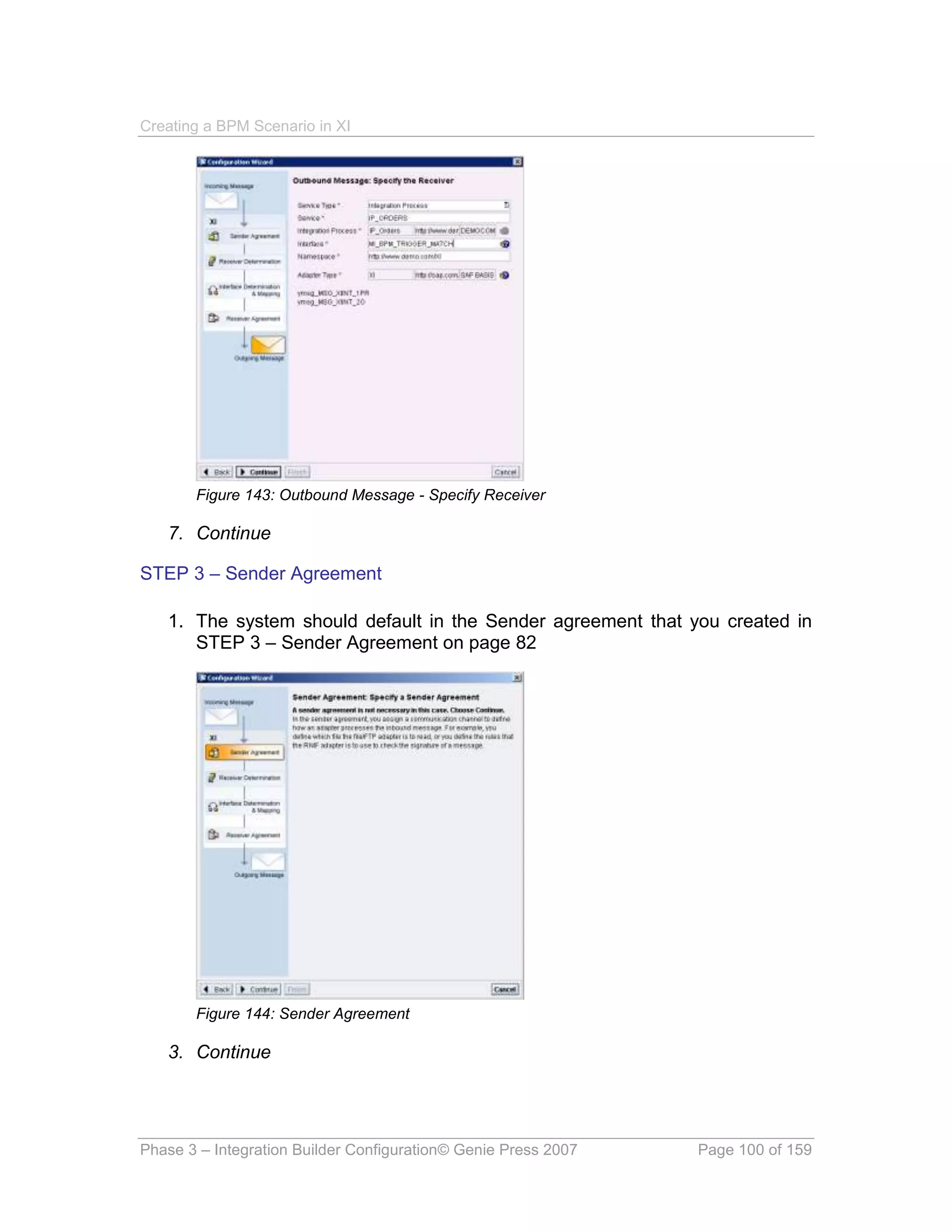
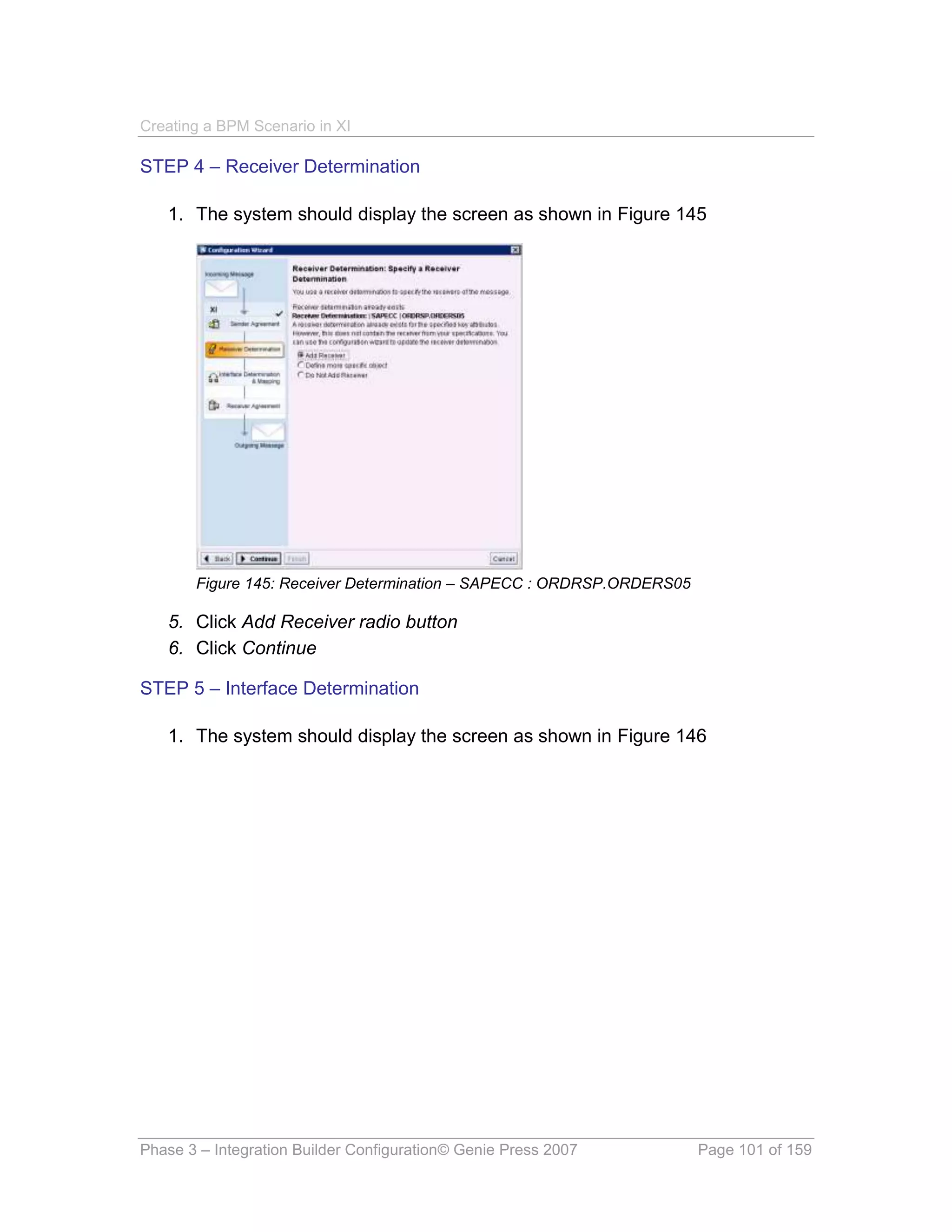
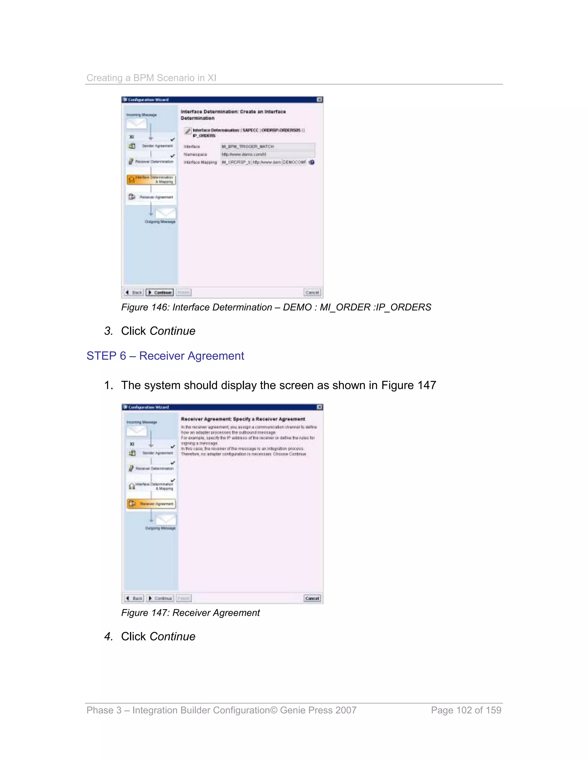

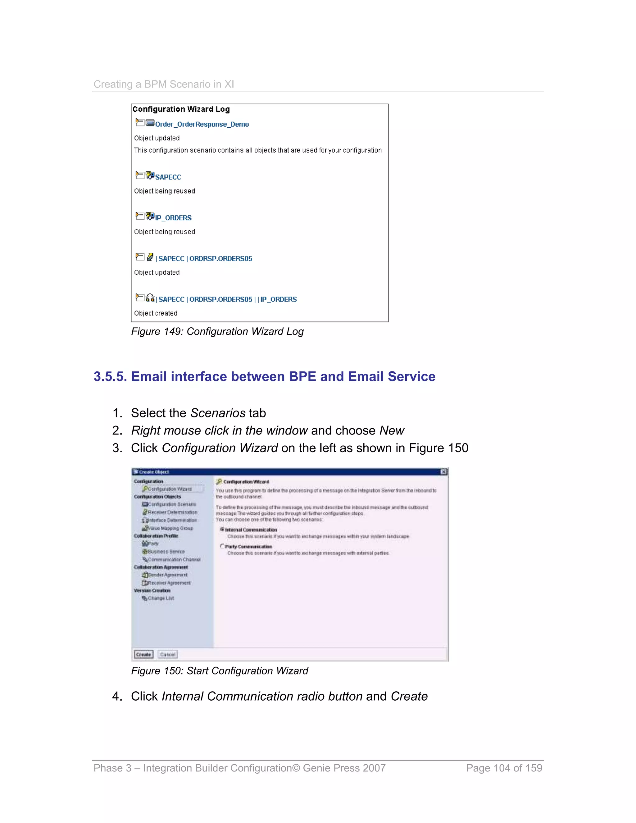
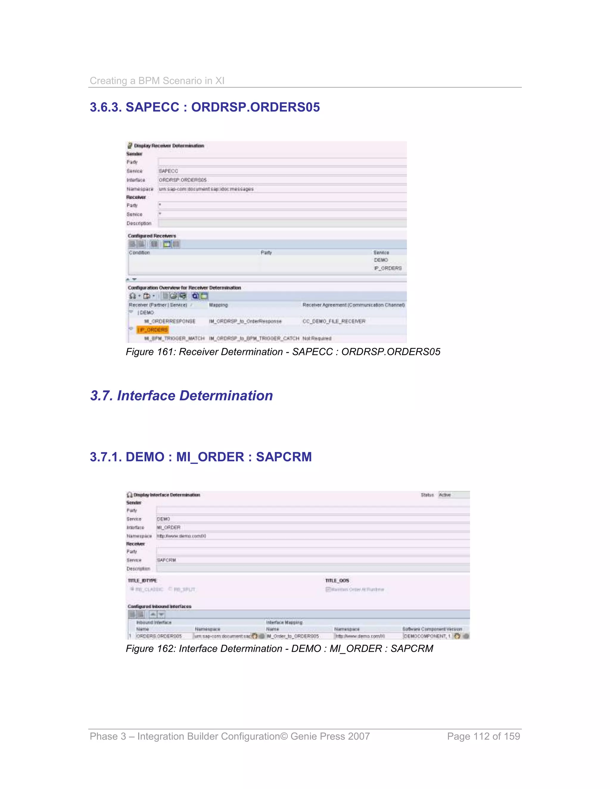
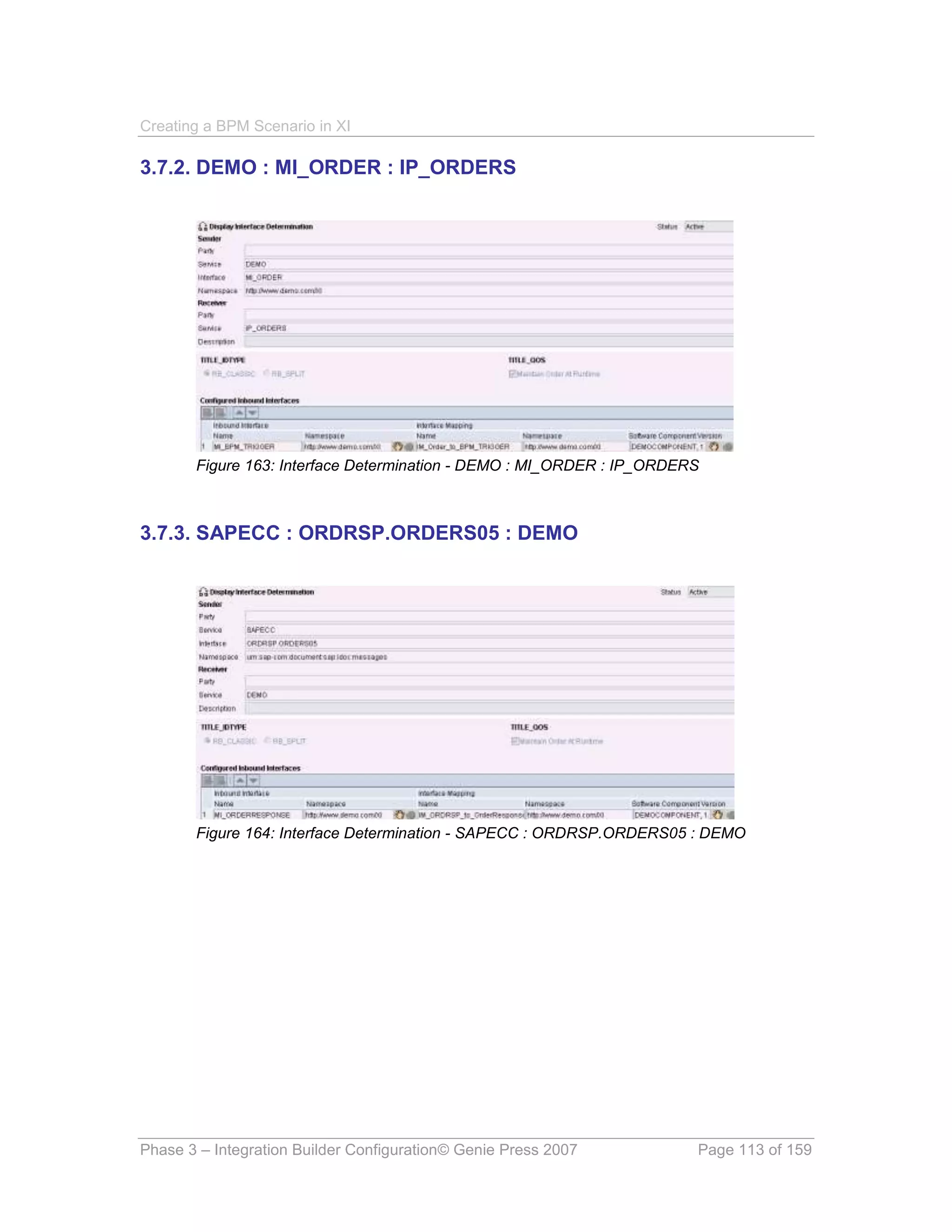
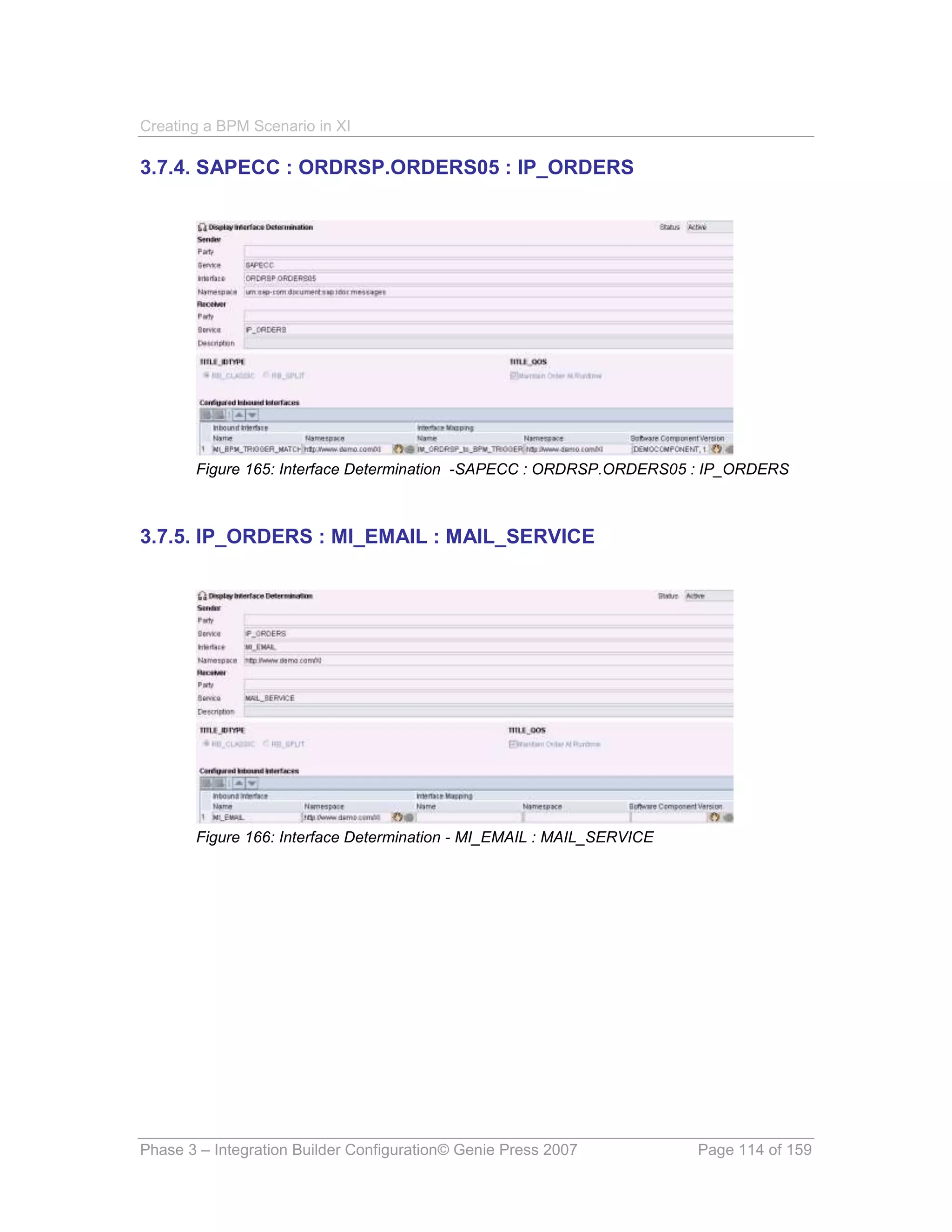
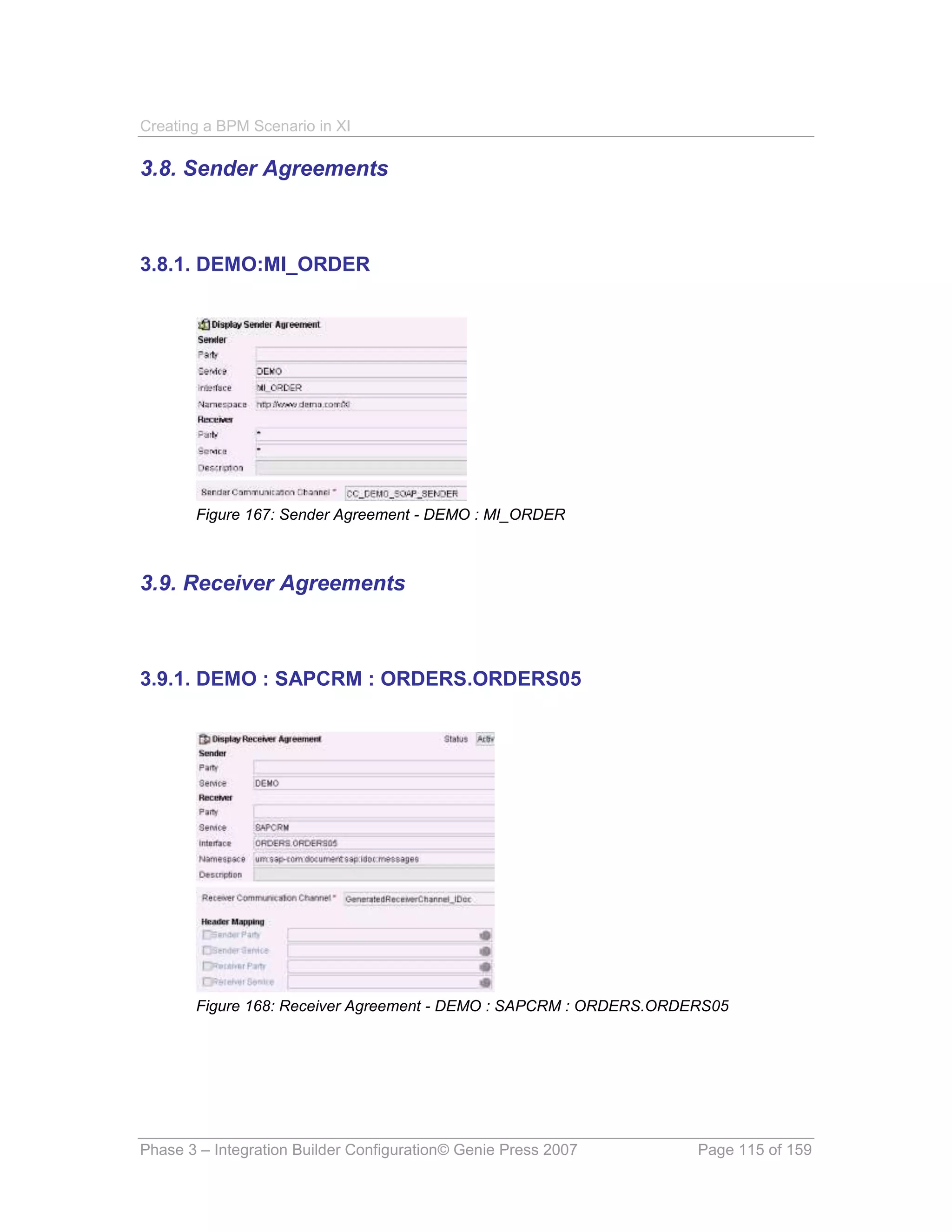
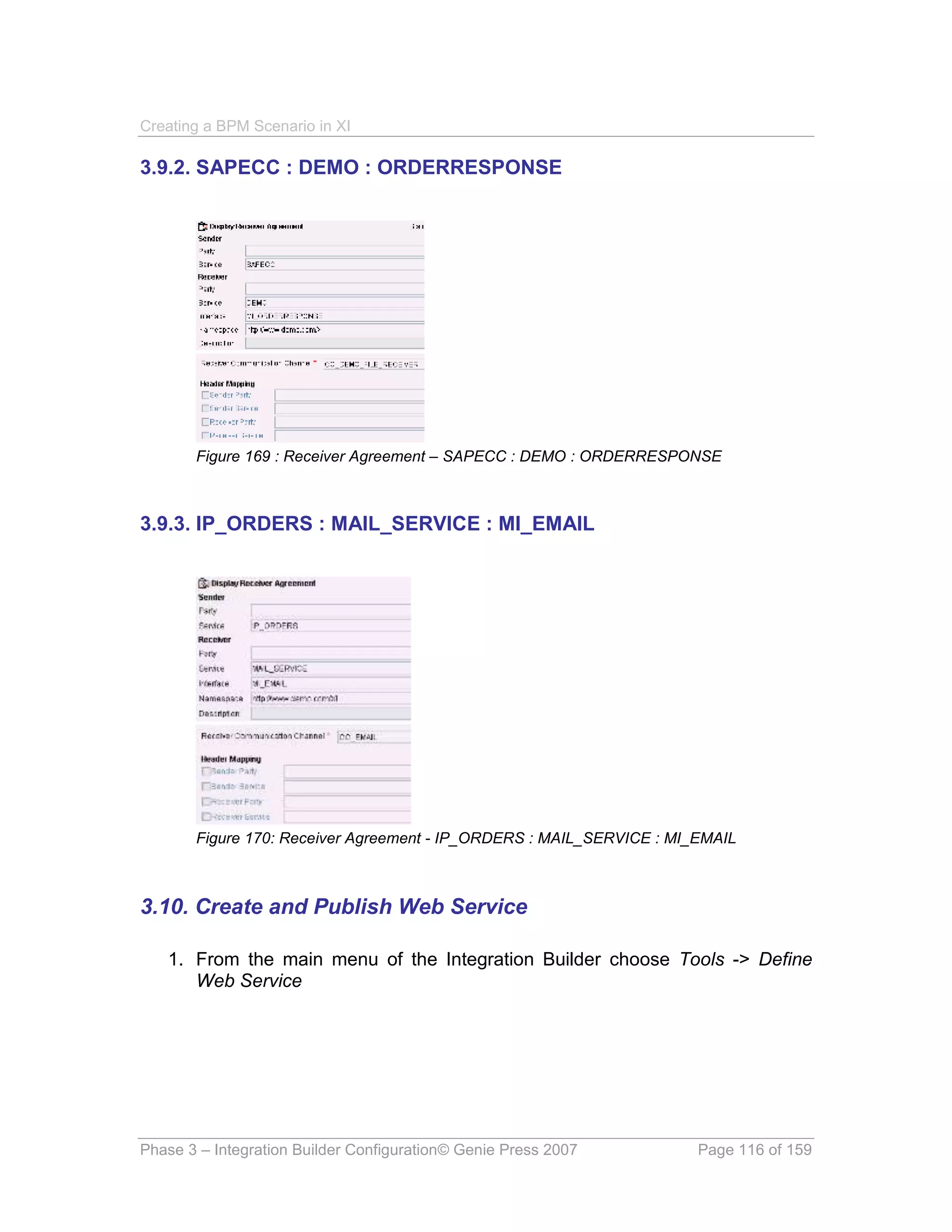
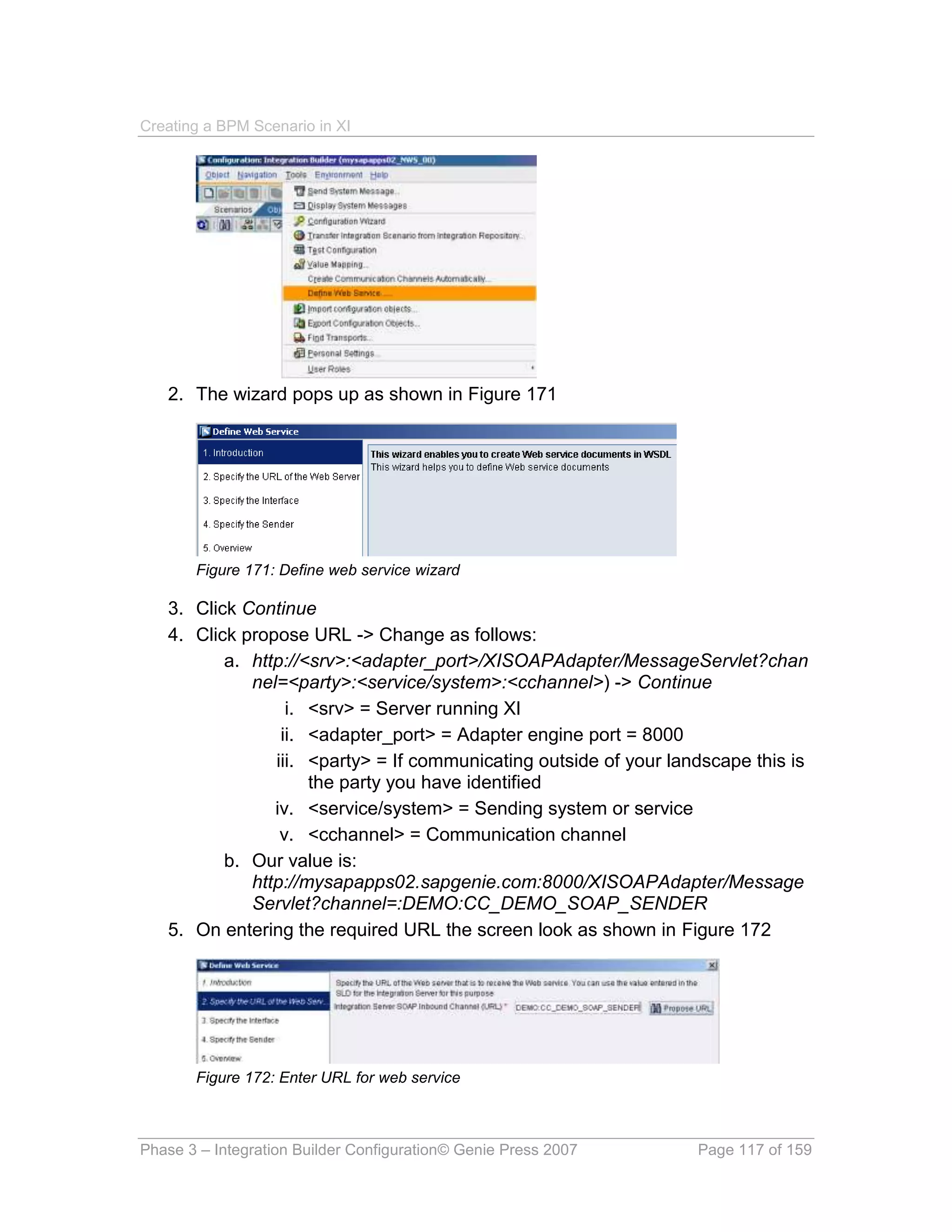
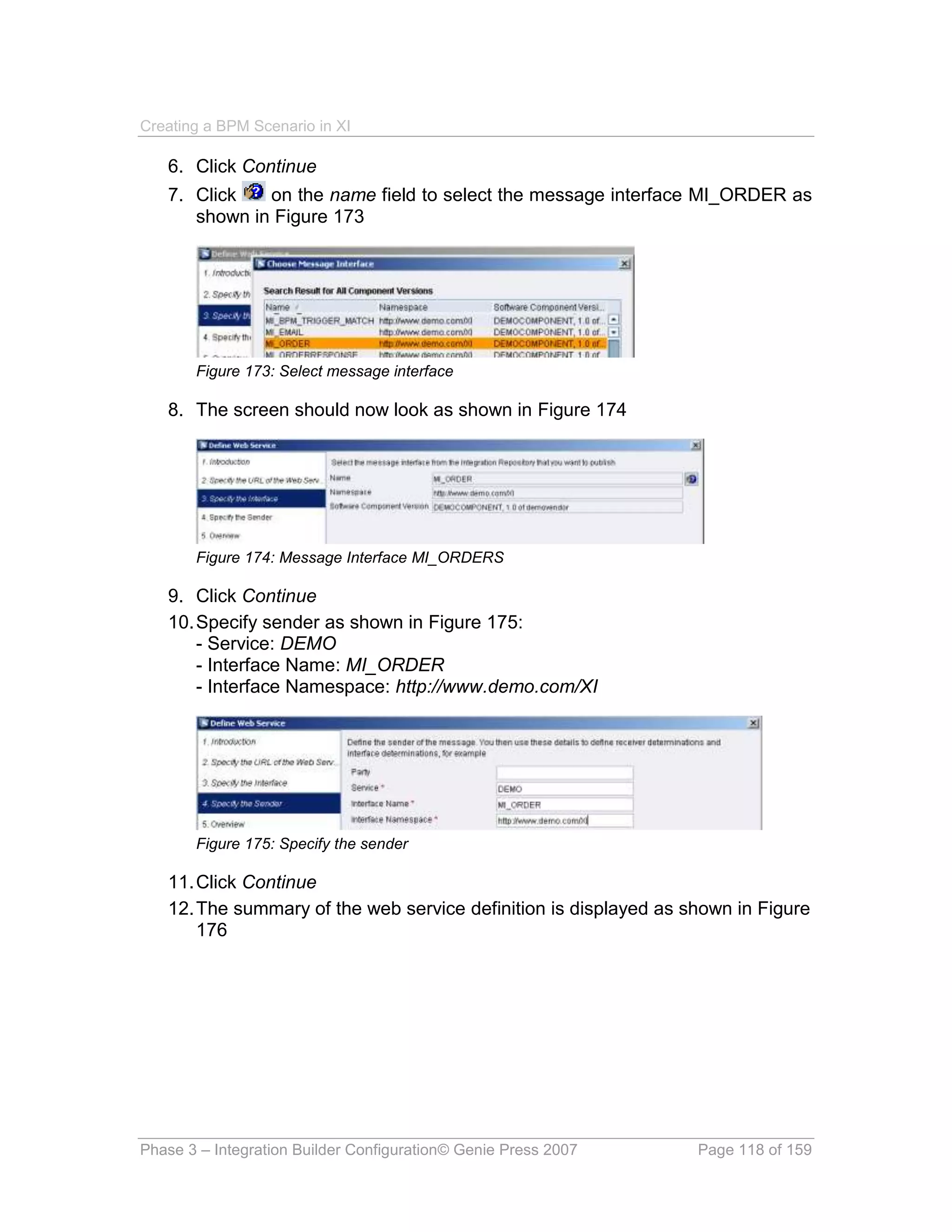
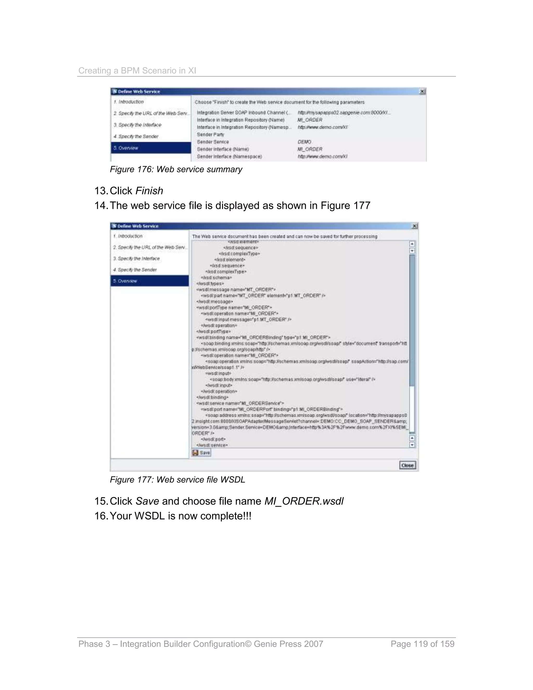
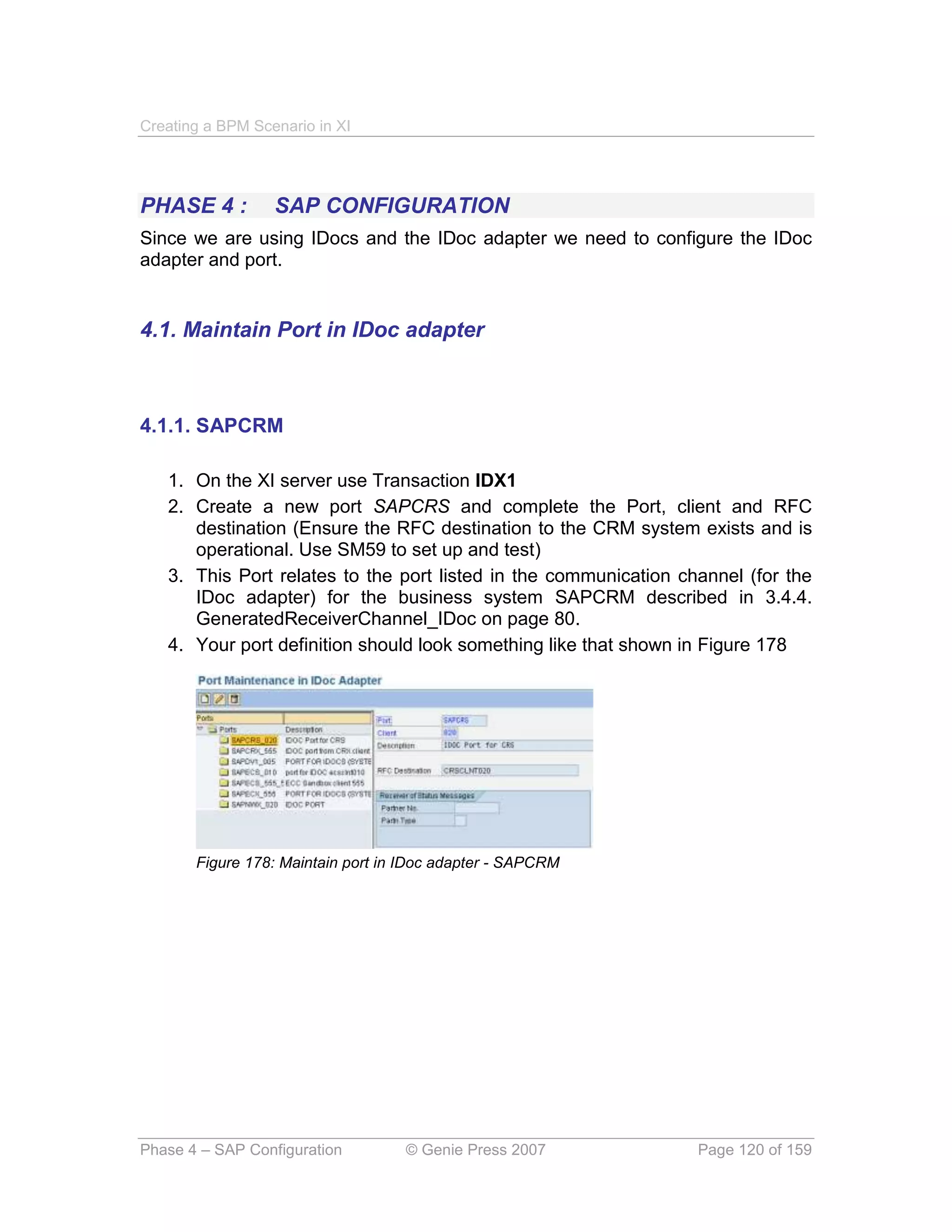
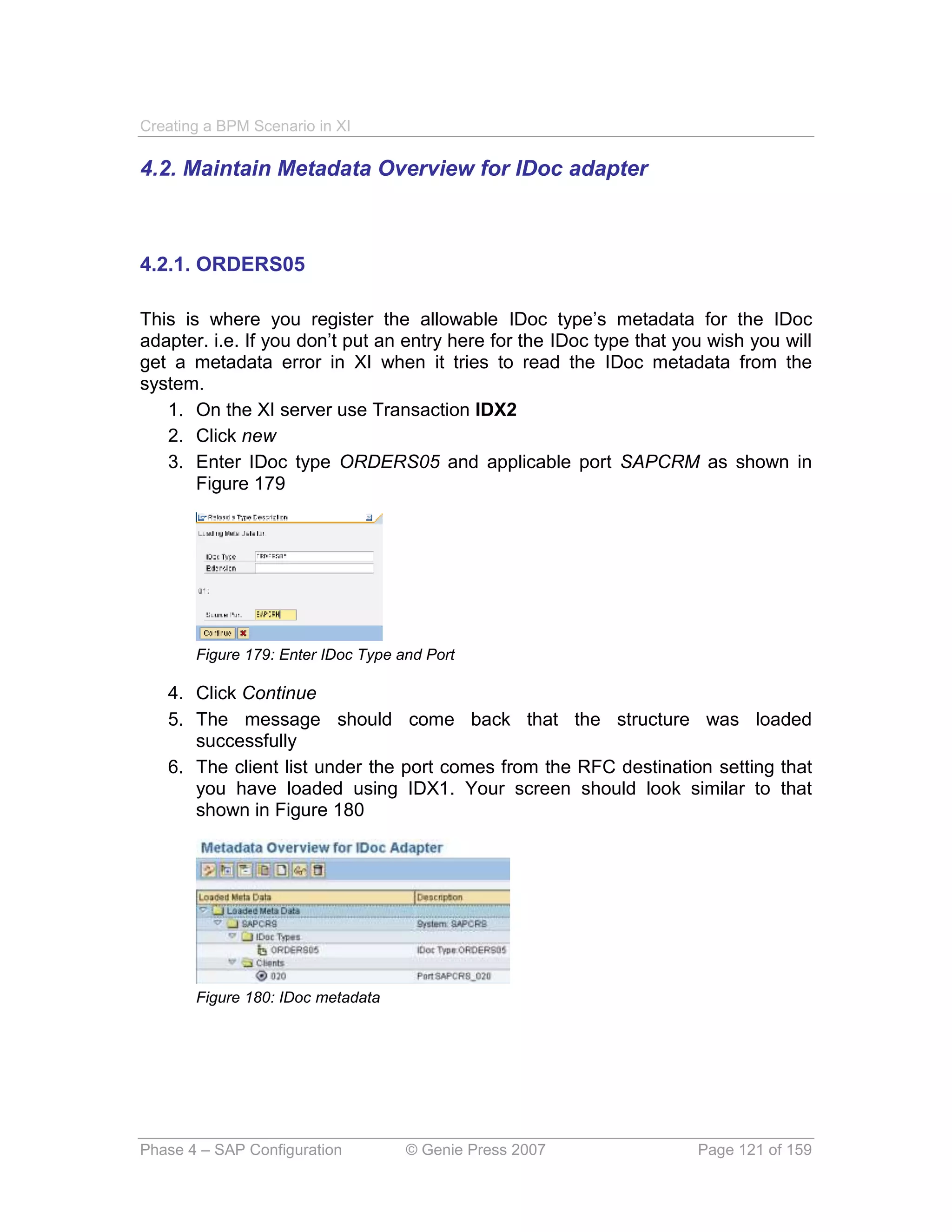
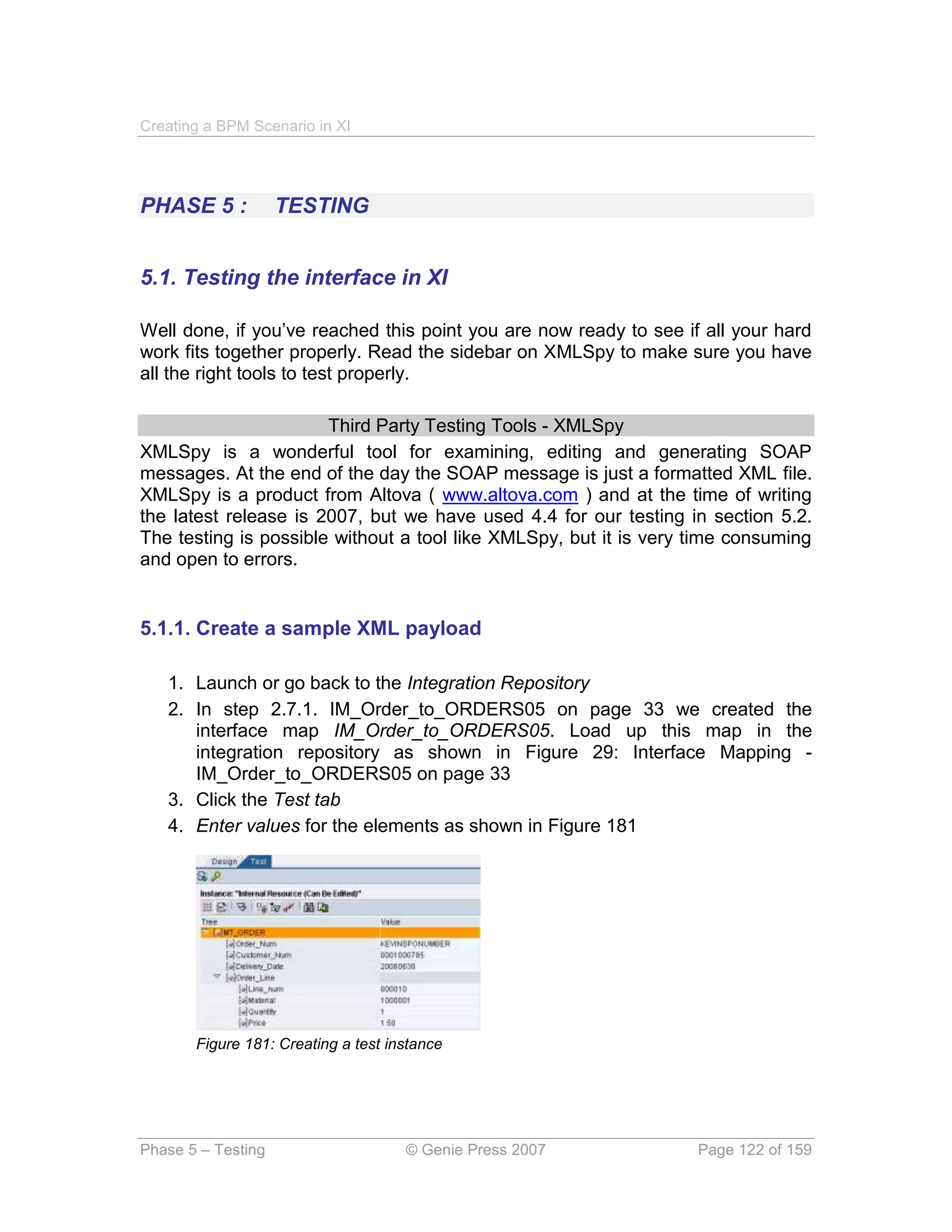
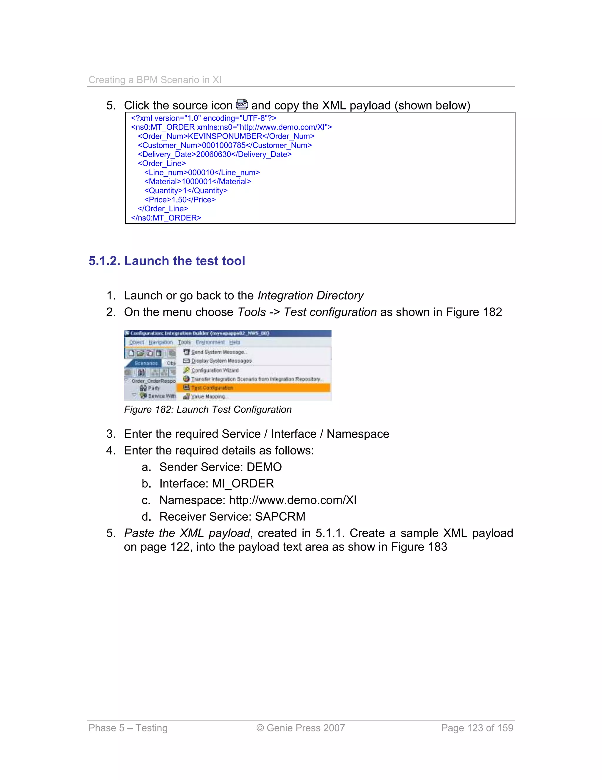
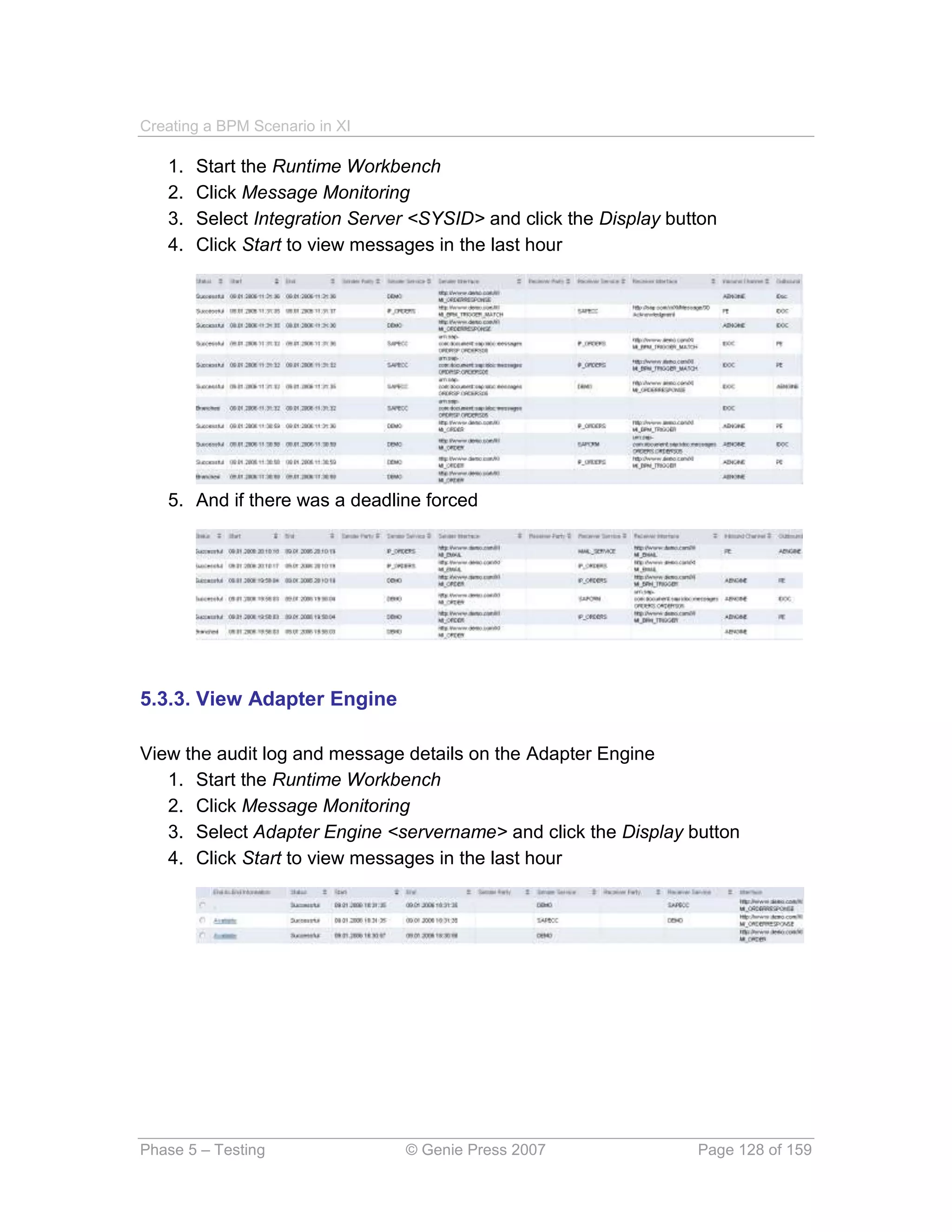
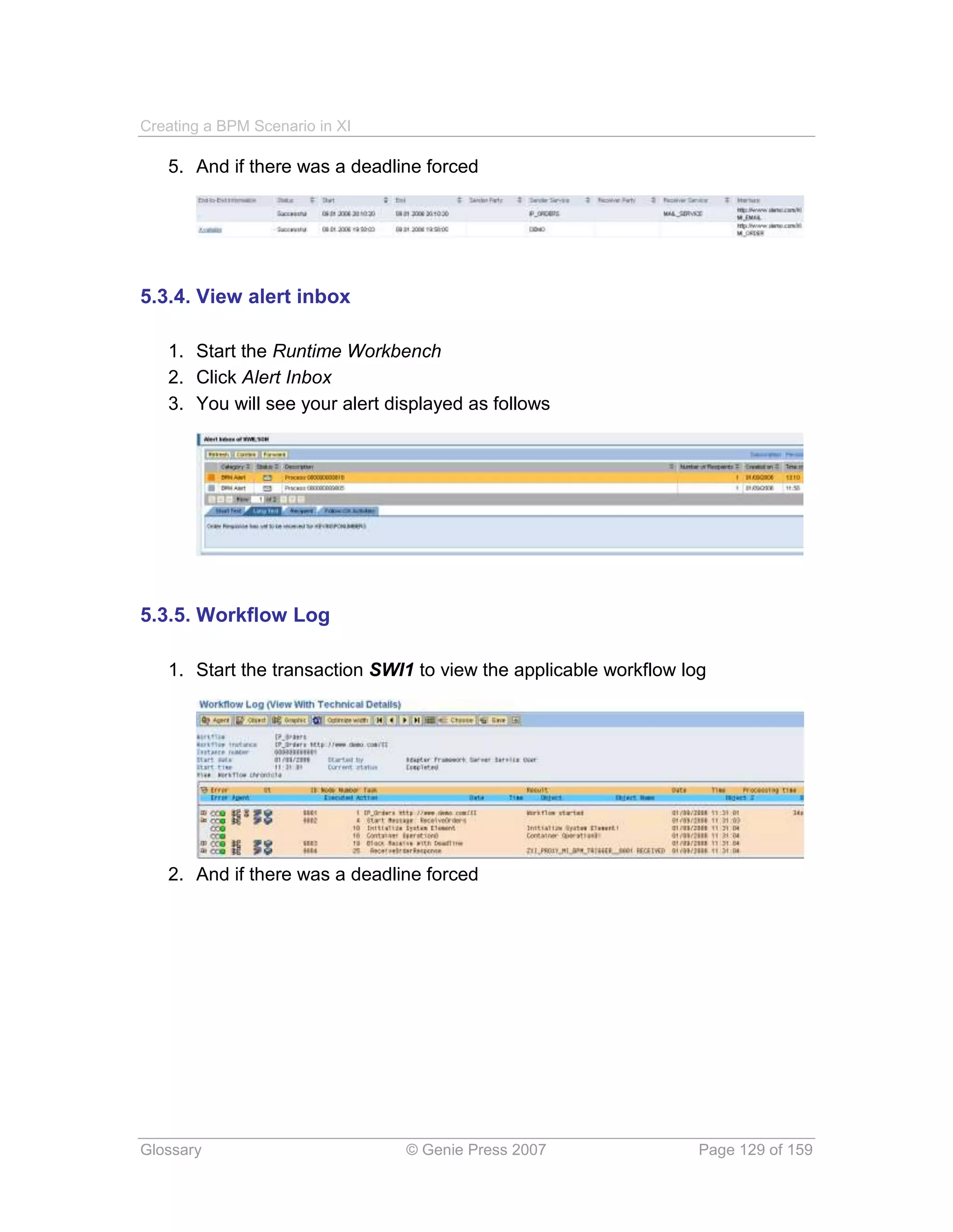
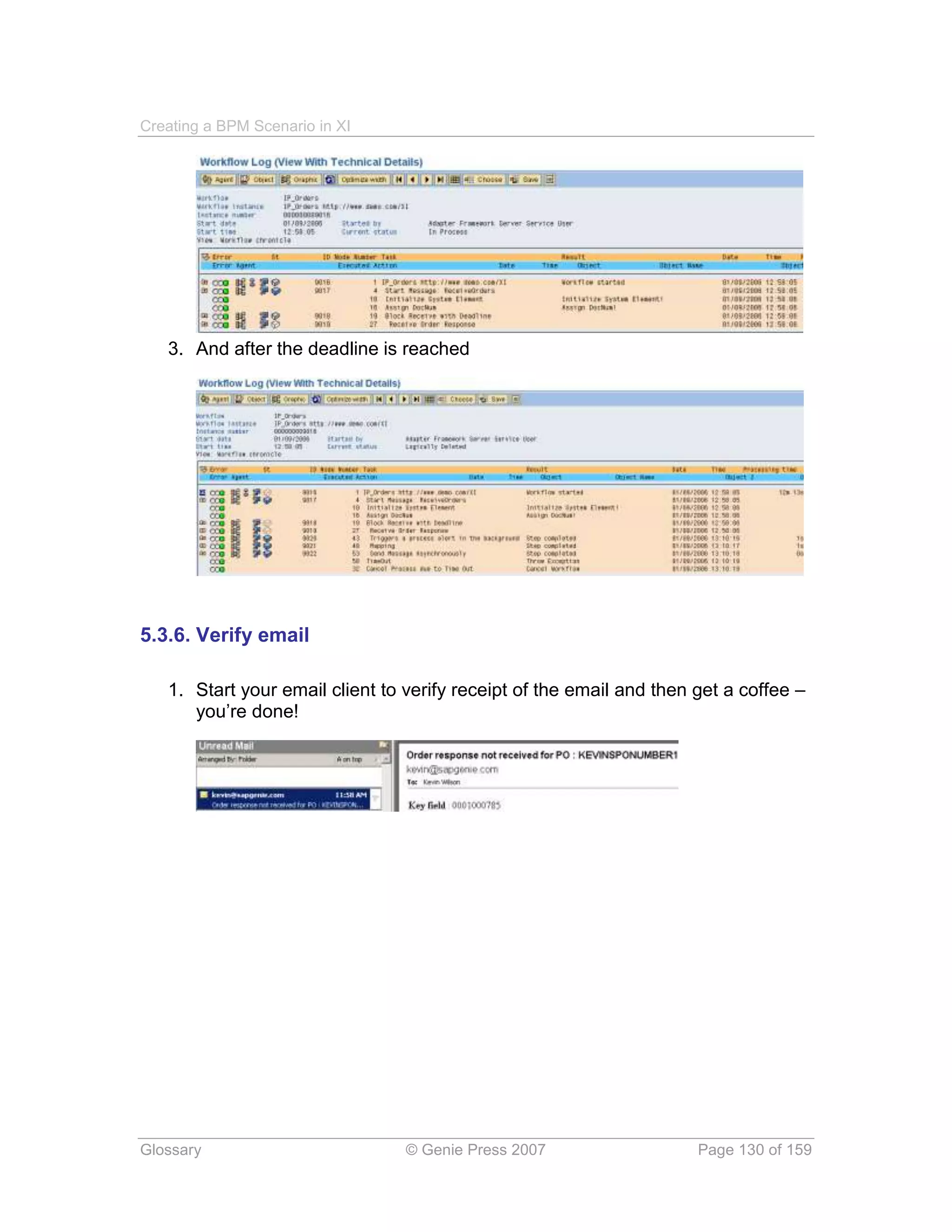
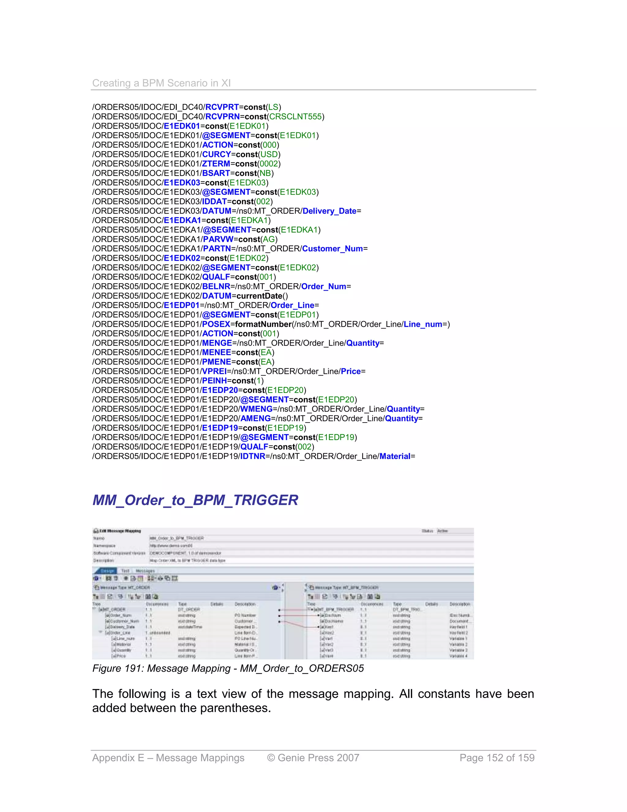
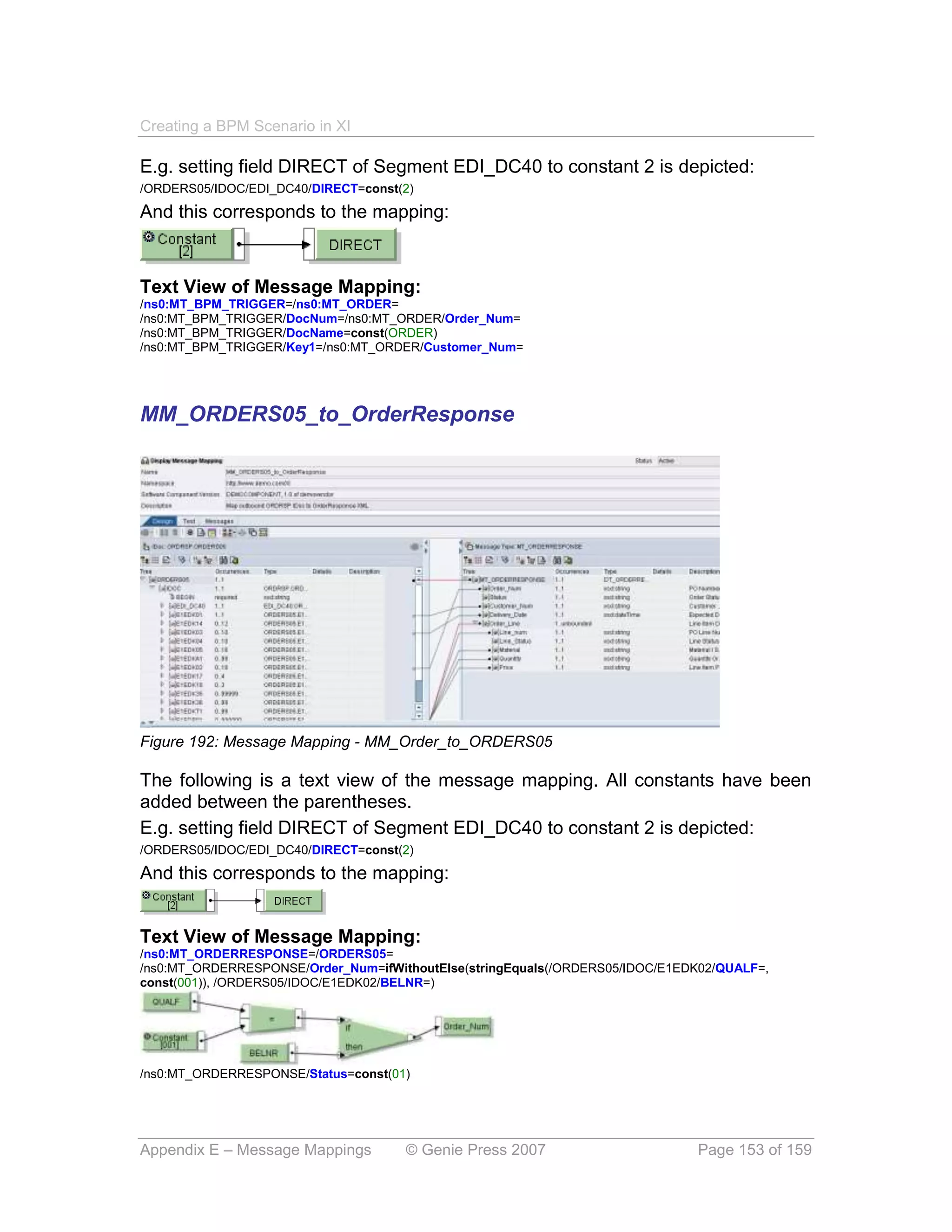
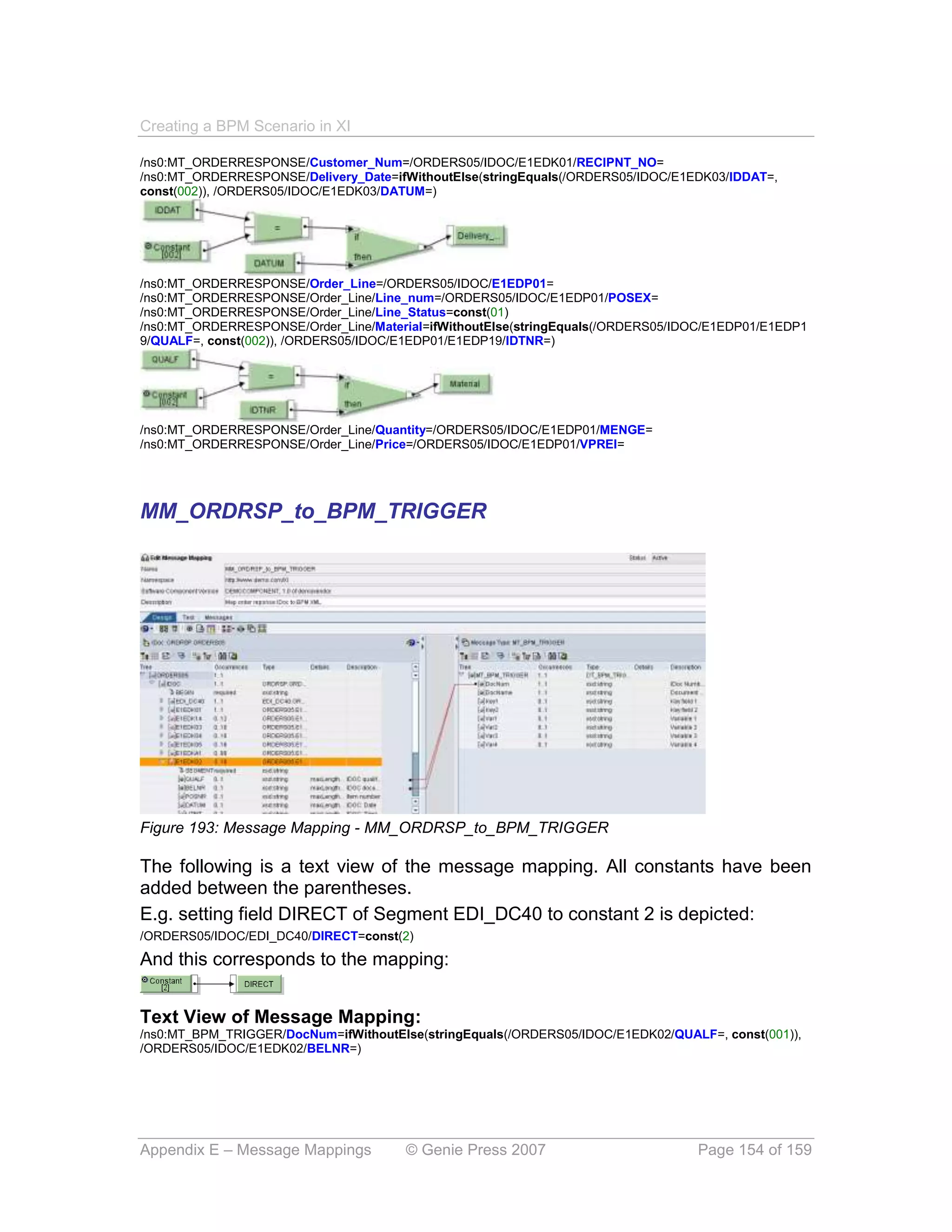


This document is a step-by-step guide for creating a BPM scenario in SAP Exchange Infrastructure 3.0, covering five main phases: system configuration, integration builder design, integration builder configuration, SAP configuration, and testing. It describes the integration of external systems, order processing, and error handling within a BPM framework. The publication serves as a practical resource for understanding and implementing integration processes involving SAP's technologies.


![Vibe Coding vs. Spec-Driven Development [Free Meetup]](https://cdn.slidesharecdn.com/ss_thumbnails/vibecodingvsspecdrivendevelopment-251209105622-43f455e7-thumbnail.jpg?width=640&height=640&fit=bounds)


