SlideShare a Scribd company logo
1 of 8
CRYOGENIC ENGINE IN ROCKET
PROPULSION
T UDAY KIRAN1
1-DEPARTMENT OF MECHANICAL ENGINEERING, AURORAS ENGINEERING COLLEGE,
BHONGIR, NALGONDA DISTRICT,ANDHRA PRADESH
E-mail: kinguday9@gmail.com
ABSTRACT–This paper gives brief study of working
of a Cryogenic Engine. While the mission and
vehicleDesigns, are not yet defined for the lunar,
Martian robotic and human exploration objectives,
cryogenic rocket engines offer the potential for higher
performance, greater design and mission flexibility.
The cryogenic engine gets its name from the
extremely cold temperatures at which liquids are
stored. It shows its efficiency over conventional
satellite launch vehicles. All cryogenic rocket engines
areliquid-propellant rocket engines or hybrid rocket
engine.This paper will summarize many of the key
technological aspects associated with using high-
performance cryogenic liquid propellant rocket
engine systems and components. This paper is
classified into two areas, the first area describes about
the history, principle, components and working,
Where’ as the second area discuss about cryogenic
fuels, advantages, disadvantages and applications of
the cryogenic engine. Historically, cryogenic rocket
engines have not been used for in-space applications
due to their additional complexity, the mission need
for high reliability. Currently only the United States,
Russia, China, France, Japan and India have
mastered cryogenic rocket technology.
INTRODUCTION
Propulsion :
It is means of creating force leading to movement.
Propulsion is of two types,
• Translational (linear, moving faster
or slower)
• Rotational (turning about an axis)
What is Cryogenics?
Cryogenics is a branch of physics concerned with the
production of very low temperatures and the effects of
these temperatures on different substances and materials.
The temperatures studied in cryogenics are those below -
243.67 degrees Fahrenheit (120 Kelvin). cryogenicists
use other temperature scales, the Kelvin and Rankine
temperature scale. Although the apparatus used for
spacecraft is specialized, some of the general approaches
are the same as used in everyday life.
Cryogenic liquids:
Under normal atmospheric conditions, at temperature
300k and pressure 1 bar, these substances are in gaseous
state. One cannot remedy the low density by increasing
the pressure because the required tank structures would
end being too heavy. The answer is to liquefy the fuels
by cooling them down. This is why the fuels are also
called cryogenic fuels. Cryogenic fuels, mainly liquid
hydrogen, have been used as rocket fuels. Liquid oxygen
is used as an oxidizer of hydrogen, but oxygen is not,
strictly speaking, a fuel. The favorite fuel and oxidizer
combination used during the boost phase are Liquid
Hydrogen (LH2) and Liquid Oxygen (LOX) which
provide a specific impulse of 445 seconds, almost double
that of hydrazine.
CRYOGENIC FUELS/PROPELLANT:
In a cryogenic propellant, the fuel and the oxidizer are in
the form of very cold, liquefied gases. These liquefied
gases are referred to as super cooled as they stay in liquid
form even though they are at a temperature lower than
the freezing point. Thus we can say that super cooled
gases used as liquid fuels are called cryogenic fuels.
These propellants are gases at normal atmospheric
conditions. But to store these propellants aboard a rocket
is a very difficult task as they have very low densities.
Hence extremely huge tanks will be required to store the
propellants. Thus by cooling and compressing them into
liquids, we can vastly increase their density and make it
possible to store them in large quantities in smaller tanks.
Cryogenic Engine Introduction
What is Cryogenic rocket engine?
A cryogenic rocket engine is a rocket engine that uses a
cryogenic fuel or oxidizer, that is, its fuel or oxidizer (or
both) is gases liquefied and stored at very low
temperatures. Notably, these engines were one of the
main factors of the ultimate success in reaching the
Moon by the Saturn V rocket. when powerful rocket
engines were first considered by the German, American
and Soviet engineers independently, all discovered that
rocket engines need high mass flow rate of both oxidizer
and fuel to generate a sufficient thrust. Hypothetically, if
propellants had been stored as pressurized gases, the size
and mass of fuel tanks themselves would severely
decrease rocket efficiency. Therefore, to get the required
mass flow rate, the only option was to cool the
propellants down to cryogenic temperatures (below −150
°C, −238 °F), converting them to liquid form. Hence, all
cryogenic rocket engines are also, by definition, either
liquid-propellant rocket engines or hybrid rocket engines.
History:
The use of liquid fuel for rocket engines was
considered as early as the beginning of 20th
century.
The Russian K.E.Ziolkowsky, the American
H.Goddard and the German-Romanian H.Oberth
worked independently on the problems of spaceflight
and soon discovered that in order to succeed, rockets
with high mass-flow were mandatory. However it was
not later until these pioneers made their attempts, the
first big liquid powered rocket the German A-4 became
reality in the mid-forties. This rocket became
successful as the V-2 weapon. Liquid oxygen was used
as the oxidizer and ethyl alcohol as the fuel which gave
the rocket more than 300KN of thrust. It`s range was
300km. As the development of rocket engines
continued, higher thrust levels were achieved when
liquid oxygen and liquid hydrocarbon were used as
fuel. This allowed the construction of the first
intercontinental rocket with a range of more than
10,000km. In the sixties, the steadily increasing
payload weights and the corresponding demand for
more thrust of the launcher lead to the use of liquid
hydrogen for the Centaur upper stage. At the peak of
this development was the US Space Shuttle Main
Engine (SSME).
Principle:
The principle of rocket propulsion depends on the
following two laws: -
(i) Newton 's third law of motion
(ii) Law of conservation of momentum
The motion of a rocket is an interesting application of
Newton’s third law of motion & momentum principle.
The rocket expels a jet of hot gases from its tail. This is
say, an action force. The jet of hot gases exerts a force on
the rocket, propelling it forward; this is the reaction
force. From the momentum point of view, the hot gases
acquire momentum in the backward direction & the
rocket acquires an equal amount of momentum in the
forward direction.
Propellants are used to provide thrust to the rockets.
These propellants on burning produces large amount of
gas, which are allowed to pass through nozzle. On
passing through the nozzle, high pressure is generated
i.e. gas comes out with high pressure. Now to increase
the thrust, one basic property is used while designing the
nozzle. The neck of the nozzle is kept very small as
compared to the body of the rocket. So the pressure of
the gas increases and so does the velocity. Thus high
thrust is achieved.
Tsiolkovsky Rocket Equation:
The Tsiolkovsky rocket equation, or ideal rocket
equation, describes the motion of vehicles that follow
the basic principle of a rocket, a device that can apply
acceleration to itself (a thrust) by expelling part of its
mass with high speed and move due to the conservation
of momentum.
www.hearlihy.co
where:
is the initial total mass, including
propellant,
is the final total mass,
is the effective exhaust velocity (
where is the specific
impulse expressed as a time period
and is Standard Gravity),
is delta-v - the maximum change of
speed of the vehicle (with no external forces
acting)
Specific Impulse:
Specific impulse (usually abbreviated Isp) is a way to
describe the efficiency of rocket and jet engines. It
represents the force with respect to the amount
of propellant used per unit time. Specific impulse is a
measure or engine performance.
Isp= Thrust / Weight flow rate of propellants.
LIMITATIONS IN SLVs :
where:
Fthrust is the thrust obtained from the engine, in newtons
(or poundals).
Isp is the specific impulse measured in seconds.
is the mass flow rate in kg/s (lb/s), which is
negative the time-rate of change of the
vehicle's mass since propellant is being expelled.
G0 is the acceleration at the Earth's surface, in m/s² (or
ft/s²).
Components:
The major components of a cryogenic rocket engine are:
Combustion Chamber (thrust chamber)
Pyrotechnic Igniter
Fuel Injector
Fuel Cryopumps,
Oxidizer Cryopumps,
Gas Turbine,
Cryo Valves,
Regulators,
Fuel Tanks,
Rocket Engine Nozzle.
In terms of feeding propellants to combustion chamber,
cryogenic rocket engines (or, generally, all liquid-
propellant engines) work in either an expander cycle, a
gas-generator cycle, a staged combustion cycle, or the
simplest pressure-fed cycle. The cryopumps are always
turbopumps powered by a flow of fuel through gas
turbines. Looking at this aspect, engines can be
differentiated into a main flow or a bypass flow
configuration. In the main flow design, all the pumped
fuel is fed through the gas turbines, and in the end
injected to the combustion chamber. In the bypass
configuration, the fuel flow is split; the main part goes
directly to the combustion chamber to generate thrust,
while only a small amount of the fuel goes to the turbine.
PROPELLANTS
SPECIFIC
IMPULSE
SOLID PROPELLANTS 265 s
EARTH STATIONARY
LIQUID PROPELLANTS
285 s
CRYOGENIC
PROPELLANTS
450 s
Gas generator cycle:
Expander cycle:
Staged combustion cycle:
Working:
Cryogenic Engines are rocket motors designed for liquid
fuels that have to be held at very low "cryogenic"
temperatures to be liquid – they would otherwise be gas
at normal temperatures. Typically Hydrogen and Oxygen
are used which need to be held below 20°K (-423°F) and
90°K (-297°F) to remain liquid. The engine components
are also cooled so the fuel doesn't boil to a gas in the
lines that feed the engine. The thrust comes from the
rapid expansion from liquid to gas with the gas emerging
from the motor at very high speed. The energy needed to
heat the fuels comes from burning them, once they are
gasses. Cryogenic engines are the highest performing
rocket motors. One disadvantage is that the fuel tanks
tend to be bulky and require heavy insulation to store the
propellant. Their high fuel efficiency, however,
outweighs this disadvantage. Air moving around the
vehicle is used to heat liquid nitrogen to a boil. Once it
boils, it turns to gas in the same way that heated water
forms steam in a steam engine. A rocket like the Ariane 5
uses oxygen and hydrogen, both stored as a cryogenic
liquid, to produce its power. The liquid nitrogen, stored
at -320 degrees Fahrenheit, is vaporized by the heat
exchanger. Nitrogen gas formed in the heat exchanger
expands to about 700 times the volume of its liquid form.
This highly pressurised gas is then fed to the expander,
where the force of the nitrogen gas is converted into
mechanical power.
Liquid-fuelled engine:
Propellant: LOX / Liquid hydrogen
The engines burn liquid hydrogen and liquid oxygen
from the Space Shuttle external tank. They are used for
propulsion during its ascent, in addition to the two more
powerful solid rocket boosters and partly the Orbital
Maneuvering System. Each engine can generate almost
1.8 meganewtons (MN) or 400,000lbf of thrust at liftoff.
The engines are capable of generating a specific impulse
Isp) of 453 seconds in a vacuum, or 363 seconds at sea
level (exhaust velocities of 4440 m/s and 3560 m/s
respectively). Overall, a space shuttle main engine
weighs approximately 3.2 t (7,000 lb). The engines are
removed after every flight and taken to the Space Shuttle
Main Engine Processing Facility (SSMEPF) for
inspection and replacement of any necessary
components. The Space Shuttle's rocket engines are
capable of operating at extreme temperatures. The liquid
hydrogen fuel is stored at −253 degrees Celsius
(−423degrees Fahrenheit). However, when burned with
liquid oxygen, the temperature in the combustion
chamber reaches 3,300 °C (6,000 °F), higher than the
boiling point of iron. Each engine consumes 1,340 liters
(340 gallons)of propellant per second. If the engine
pumped water instead of liquid oxygen and liquid
hydrogen, an average-sized swimming pool could be
drained in 75seconds - or 25 seconds for the sum of the
three used for the space shuttle launch. The engines
perform as follows: Fuel and oxidizer from the external
tank enters the orbiter at the orbiter/external tank
umbilical disconnect and then the orbiter's main
propulsion system feed lines. There the fuel and oxidizer
each branch out into three parallel paths, to each engine.
In each branch, prevalves must be opened to permit flow
to the low-pressure fuel or oxidizer turbopump
Oxidizer system:
The Low Pressure Oxidizer Turbopump (LPOTP) is an
axial-flow pump driven by a six-stage turbine powered
by liquid oxygen. It boosts the liquid oxygen's pressure
from 0.7 to 2.9 MPa (100 to 420 psi). The flow from the
LPOTP is supplied to the High-Pressure Oxidizer
Turbopump (HPOTP). During engine operation, the
pressure boost permits the High Pressure Oxidizer
Turbine to operate at high speeds without cavitating. The
LPOTP operates at approximately 5,150 rpm. The
LPOTP, which measures approximately 450 by 450 mm
(18 by 18 inches), is connected to the vehicle propellant
ducting and supported in a fixed position by the orbiter
structure.
The HPOTP consists of two single-stage centrifugal
pumps (a main pump and a pre-burner pump) mounted
on a common shaft and driven by a two-stage, hot-gas
turbine. The main pump boosts the liquid oxygen's
pressure from 2.9 to 30 MPa (420 to 4,300 psi) while
operating at approximately 28,120 rpm. The HPOTP
discharge flow splits into several paths, one of which is
routed to drive the LPOTP turbine. Another path is
routed to and through the main oxidizer valve and enters
into the main combustion chamber. Another small flow
path is tapped off and sent to the oxidizer heat
exchanger. The liquid oxygen flows through an anti-
flood valve that prevents it from entering the heat
exchanger until sufficient heat is present to convert the
liquid oxygen to gas. The heat exchanger utilizes the heat
contained in the discharge gases from the HPOTP turbine
to convert the liquid oxygen to gas. The gas is sent to a
manifold and is then routed to the external tank to
pressurize the liquid oxygen tank. Another path enters
the HPOT second-stage preburner pump to boost the
liquid oxygen's pressure from 30 to 51 MPa (4,300 psia
to 7,400 psia). It passes through the oxidizer preburner
oxidizer valve into the oxidizer preburner and through
the fuel preburner oxidizer valve into the fuel preburner.
The HPOTP measures approximately 600 by 900 mm
(24 by 36 inches). It is attached by flanges to the hot-gas
manifold.
The HPOTP turbine and HPOTP pumps are
mounted on a common shaft. Mixing of the fuel-rich hot
gas in the turbine section and the liquid oxygen in the
main pump could create a hazard. To prevent this, the
two sections are separated by a cavity that is
continuously purged by the MPS engine helium supply
during engine operation. Two seals minimize leakage
into the cavity. One seal is located between the turbine
section and the cavity, and the other is between the pump
section and cavity. Loss of helium pressure in this cavity
results in an automatic engine shutdown.
Hydrogen fuel system:
Fuel enters the orbiter at the liquid hydrogen feed line
disconnect valve, then flows into the orbiter liquid
hydrogen feed line manifold and branches out into three
parallel paths to each engine. In each liquid hydrogen
branch, a prevalve permits liquid hydrogen to flow to the
low-pressure fuel turbopump when the prevalve is open.
The Low Pressure Fuel Turbopump (LPFTP) is an axial-
flow pump driven by a two-stage turbine powered by
gaseous hydrogen. It boosts the pressure of the liquid
hydrogen from 30 to 276 psia (0.2 to 1.9 MPa) and
supplies it to the High-Pressure Fuel Turbopump
(HPFTP). During engine operation, the pressure boost
provided by the LPFTP permits the HPFTP to operate at
high speeds without cavitating. The LPFTP operates at
approximately 16,185 rpm. The LPFTP is approximately
450 by 600 mm (18 by 24 inches). It is connected to the
vehicle propellant ducting and is supported in a fixed
position by the orbiter structure 180 degrees from the
LPOTP.
The HPFTP is a three-stage centrifugal pump driven by a
two-stage, hot-gas turbine. It boosts the pressure of the
liquid hydrogen from 1.9 to 45 MPa (276 to 6,515 psia).
The HPFTP operates at approximately 35,360 rpm. The
discharge flow from the turbopump is routed to and
through the main valve and then splits into three flow
paths. One path is through the jacket of the main
combustion chamber, where the hydrogen is used to cool
the chamber walls. It is then routed from the main
combustion chamber to the LPFTP, where it is used to
drive the LPFTP turbine. A small portion of the flow
from the LPFTP is then directed to a common manifold
from all three engines to form a single path to the
external tank to maintain liquid hydrogen tank
pressurization. The remaining hydrogen passes between
the inner and outer walls to cool the hot-gas manifold
and is discharged into the main combustion chamber.
The second hydrogen flow path from the main fuel valve
is through the engine nozzle (to cool the nozzle). It then
joins the third flow path from the chamber coolant valve.
The combined flow is then directed to the fuel and
oxidizer preburners. The HPFTP is approximately 550 by
1100 mm (22 by 44 inches). It is attached by flanges to
the hot-gas manifold.
Pre-burners and thrust control system:
The oxidizer and fuel preburners are welded to the hot-
gasmanifold. The fuel and oxidizer enter the preburners
and are mixed so that efficient combustion can occur.
The augmented spark igniter is a small combination
chamber located in the center of the injector of each
preburner. The two dual-redundant spark igniters, which
are activated by the engine controller, are used during the
engine start sequence to initiate combustion in each
preburner. They are turned off after approximately three
seconds because the combustion process is then self-
sustaining. The preburners produce the fuel-rich hot gas
that passes through the turbines to generate the power to
operate the high-pressure turbopumps. The oxidizer
preburner's outflow drives a turbine that is connected to
the HPOTP and the oxidizer preburner pump. The fuel
preburner's outflow drives a turbine that is connected to
the HPFTP.
The speed of the HPOTP and HPFTP turbines depends
on the position of the corresponding oxidizer and fuel
preburner oxidizer valves. These valves are positioned by
the engine controller, which uses them to throttle the
flow of liquid oxygen to the preburners and, thus, control
engine thrust. The oxidizer and fuel preburner oxidizer
valves increase or decrease the liquid oxygen flow, thus
increasing or decreasing preburner chamber pressure,
HPOTP and HPFTP turbine speed, and liquid oxygen
and gaseous hydrogen flow into the main combustion
chamber, which increases or decreases engine thrust,
thus throttling the engine. The oxidizer and fuel
preburner valves operate together to throttle the engine
and maintain a constant 6-1 propellant mixture ratio.
The main oxidizer valve and the main fuel valve control
the flow of liquid oxygen and liquid hydrogen into the
engine and are controlled by each engine controller.
When an engine is operating, the main valves are fully
open.
Cooling control system:
A coolant control valve is mounted on the combustion
chamber coolant bypass duct of each engine. The engine
controller regulates the amount of gaseous hydrogen
allowed to bypass the nozzle coolant loop, thus
controlling its temperature. The chamber coolant valve is
100 % open before engine start. During engine operation,
it will be 100 % open for throttle settings of 100 to
109 % for maximum cooling. For throttle settings
between 65 to 100 %, its position will range from 66.4 to
100 % open for reduced cooling.
Combustion chamber and nozzle
Each engine main combustion chamber receives fuel-rich
hot gas from a hot-gas manifold cooling circuit. The
gaseous hydrogen and liquid oxygen enter the chamber at
the injector, which mixes the propellants. A small
augmented spark igniter chamber is located in the center
of the injector. The dual-redundant igniter is used during
the engine start sequence to initiate combustion. The
igniters are turned off after approximately three seconds
because the combustion process is self-sustaining. The
main injector and dome assembly is welded to the hot-
gas manifold. The main combustion chamber also is
bolted to the hot-gas manifold.
The inner surface of each combustion chamber, as well
as the inner surface of each nozzle, is cooled by liquid
hydrogen flowing through brazed stainless steel tube-
wall coolant passages. The nozzle assembly is a bell-
shaped extension bolted to the main combustion
chamber. The nozzle is 2.9 m (113 inches) long, and the
outside diameter of the exit is 2.4 m (94 inches). A
support ring welded to the forward end of the nozzle is
the engine attach point to the orbiter-supplied heat shield.
Thermal protection is necessary because of the exposure
portions of the nozzles experience during the launch,
ascent, on-orbit and entry phases of a mission. The
insulation consists of four layers of metallic batting
covered with a metallic foil and screening.For a nozzle
able to run at sea level, the SSME nozzle has an
unusually large expansion ratio (about 77) for the
chamber pressure. A nozzle that large would normally
undergo flow separation of the jet from the nozzle which
would cause control difficulties and could even
mechanically damage the vehicle. Instead the
Rocketdyne engineers varied the angle of the nozzle,
reducing it near the exit. This raises the pressure just
around the rim to between 4.6 and 5.7 psi, and prevents
flow separation. The inner part of the flow is at much
lower pressure, around 2 psi or less.
Main valves:
The five propellant valves on each engine (oxidizer
preburner oxidizer, fuel preburner oxidizer, main
oxidizer, main fuel, and chamber coolant) are
hydraulically actuated and controlled by electrical signals
from the engine controller. They can be fully closed by
using the MPS engine helium supply system as a backup
actuation system.
The main oxidizer valve and fuel bleed valve are used
after shutdown. The main oxidizer valve is opened
during a propellant dump to allow residual liquid oxygen
to be dumped overboard through the engine, and the fuel
bleed valve is opened to allow residual liquid hydrogen
to be dumped through the liquid hydrogen fill and drain
valves overboard. After the dump is completed, the
valves close and remain closed for the remainder of the
mission.
Controller:
An important innovation was the inclusion of an
integrated controller in the engine itself: the SSME
controller. This digital computer (originally composed
with two redundant Honeywell HDC-601 computers, and
later replaced with a system with two redundant
Motorola 68000 processors) has two tasks: control the
engine and its burning process, and check itself. This
arrangement greatly simplified the wiring between the
engine and the shuttle, because all the sensors and
actuators are connected directly to it. Using a dedicated
system also simplified the software and improved its
reliability. Two independent computers, A and B, form
the controller, giving redundancy to the system. The
failure of the system A will automatically switch to the
system B without impeding operational capabilities; the
failure of the system B will provide a graceful shutdown
of the engine.
Advantages:
Storable liquid stages of PSLV and GSLV engines used
presently release harmful products to the environment.
The trend worldwide is to change over to eco-friendly
propellants. Liquid engines working with cryogenic
propellants (liquid oxygen and liquid hydrogen) and semi
cryogenic engines using liquid oxygen and kerosene are
considered relatively environment friendly, non-toxic
and non corrosive. In addition, the propellants for semi-
cryogenic engine are safer to handle & store. It will also
reduce the cost of launch operations. This advanced
propulsion technology is now available only with Russia
and USA. India is capable to meet existing mission
requirements. The semi cryogenic engine will facilitate
applications for future space missions such as the
Reusable Launch Vehicle, Unified Launch Vehicle and
vehicle for interplanetary missions.
High Energy per unit mass:
Propellants like oxygen and hydrogen in liquid form
give very high amounts of energy per unit mass due to
which the amount of fuel to be carried aboard the rockets
decreases.
Clean Fuels:
Hydrogen and oxygen are extremely clean fuels. When
they combine, they give out only water. This water is
thrown out of the nozzle in form of very hot vapour.
Thus the rocket is nothing but a high burning steam
engine
Economical :
Use of oxygen and hydrogen as fuels is very
economical, as liquid oxygen costs less than gasoline.
Disadvantages:
 Boil off Rate.
 Highly reactive gases.
 Leakage.
 Hydrogen Embrittlement .
 Zero Gravity conditions.
Applications:
Cryogenic engines are the highest performing rocket
motors and are widely used in Aerospace and defense
applications.
The next generation of the Rocket Engines:
 All rocket engines burn their fuel to generate
thrust. If any other engine can generate enough
thrust, that can also be used as a rocket engine
 There are a lot of plans for new engines that
the NASA scientists are still working with.
One of them is the “ Xenon ion Engine” . This
engine accelerate ions or atomic particles to
extremely high speeds to create thrust more
efficiently. NASA's Deep Space-1 spacecraft
will be the first to use ion engines for
propulsion.
 There are some alternative solutions like
Nuclear thermal rocket engines, Solar thermal
rockets, the electric rocket etc.
 We are looking forward that in the near future
there will be some good technology to take us
into space
 Interplanetary travel will require advanced
forms of propulsion technology:
1. Antimatter
2. Nuclear fusion
3. Non-rocket methods
Conclusion:
Present programs relate to Cryogenic Upper
Stages for launch vehicles.
Semi-cryogenicengines, Hypergolic engines
are being developed.
References:
1. http://en.wikipedia.org/wiki/Spacecraft_propul
sion
2. http://en.wikipedia.org/wiki/Cryogenic_engine
3. http://en.wikipedia.org/wiki/Cryogenic_fuel
4. http://en.wikipedia.org/wiki/Liquid-
propellant_rocket
5. http://www.nasa.gov/mission_pages/constellati
on/main/index2.html
6. http://en.wikipedia.org/wiki/Ion_thruster.
.

More Related Content

What's hot

cryogenic engine ppt by santosh
 cryogenic engine ppt by santosh cryogenic engine ppt by santosh
cryogenic engine ppt by santoshSantosh Santu
 
The basics of Rocket Propulsion Part 1
The basics of Rocket Propulsion Part 1The basics of Rocket Propulsion Part 1
The basics of Rocket Propulsion Part 1Zack Wanambwa
 
Cryogenic rocket engines report
Cryogenic rocket engines reportCryogenic rocket engines report
Cryogenic rocket engines reportpandu_sravs
 
UNIT - V ROCKET PROPULSION
UNIT - V ROCKET PROPULSIONUNIT - V ROCKET PROPULSION
UNIT - V ROCKET PROPULSIONsureshkcet
 
Rocket propulsion
Rocket propulsionRocket propulsion
Rocket propulsionAman Dhanda
 
Automobile engines
Automobile enginesAutomobile engines
Automobile engineskgmahesh123
 
Hybrid Rocket propulsion
Hybrid Rocket propulsionHybrid Rocket propulsion
Hybrid Rocket propulsionDaniel Digre
 
Cyogenic rocket engine report
Cyogenic rocket engine reportCyogenic rocket engine report
Cyogenic rocket engine reportSelf-employed
 
SOLID ROCKET PROPULSION PPT ( SPACE SOLID ROCKET ).pptx
SOLID ROCKET PROPULSION PPT ( SPACE SOLID ROCKET ).pptxSOLID ROCKET PROPULSION PPT ( SPACE SOLID ROCKET ).pptx
SOLID ROCKET PROPULSION PPT ( SPACE SOLID ROCKET ).pptxAmarnathGhosh8
 
PRESENTATION ON CRYOGENIC ROCKET ENGINE
PRESENTATION ON CRYOGENIC ROCKET ENGINEPRESENTATION ON CRYOGENIC ROCKET ENGINE
PRESENTATION ON CRYOGENIC ROCKET ENGINESelf-employed
 
Spacecraft Propulsion
Spacecraft PropulsionSpacecraft Propulsion
Spacecraft PropulsionNilesh Nawale
 
Rockets Propulsion
Rockets PropulsionRockets Propulsion
Rockets PropulsionDinesh Babu
 
Gas dynamics and jet propulsion – presentationof problemsanswers
Gas dynamics and jet propulsion – presentationof problemsanswersGas dynamics and jet propulsion – presentationof problemsanswers
Gas dynamics and jet propulsion – presentationof problemsanswersVaidyanathan Ramakrishnan
 
Turbojet engines
Turbojet enginesTurbojet engines
Turbojet enginespranav teli
 
Fundamentals Of Rockets & Missiles
Fundamentals Of Rockets & MissilesFundamentals Of Rockets & Missiles
Fundamentals Of Rockets & MissilesJim Jenkins
 

What's hot (20)

cryogenic engine ppt by santosh
 cryogenic engine ppt by santosh cryogenic engine ppt by santosh
cryogenic engine ppt by santosh
 
Aircraft propulsion system
Aircraft propulsion systemAircraft propulsion system
Aircraft propulsion system
 
The basics of Rocket Propulsion Part 1
The basics of Rocket Propulsion Part 1The basics of Rocket Propulsion Part 1
The basics of Rocket Propulsion Part 1
 
Cryogenic rocket engines report
Cryogenic rocket engines reportCryogenic rocket engines report
Cryogenic rocket engines report
 
UNIT - V ROCKET PROPULSION
UNIT - V ROCKET PROPULSIONUNIT - V ROCKET PROPULSION
UNIT - V ROCKET PROPULSION
 
Rocket propulsion
Rocket propulsionRocket propulsion
Rocket propulsion
 
Jet propulsion
Jet propulsionJet propulsion
Jet propulsion
 
Automobile engines
Automobile enginesAutomobile engines
Automobile engines
 
Hybrid Rocket propulsion
Hybrid Rocket propulsionHybrid Rocket propulsion
Hybrid Rocket propulsion
 
Cyogenic rocket engine report
Cyogenic rocket engine reportCyogenic rocket engine report
Cyogenic rocket engine report
 
SOLID ROCKET PROPULSION PPT ( SPACE SOLID ROCKET ).pptx
SOLID ROCKET PROPULSION PPT ( SPACE SOLID ROCKET ).pptxSOLID ROCKET PROPULSION PPT ( SPACE SOLID ROCKET ).pptx
SOLID ROCKET PROPULSION PPT ( SPACE SOLID ROCKET ).pptx
 
CRYOGENICS BASICS
CRYOGENICS BASICSCRYOGENICS BASICS
CRYOGENICS BASICS
 
PRESENTATION ON CRYOGENIC ROCKET ENGINE
PRESENTATION ON CRYOGENIC ROCKET ENGINEPRESENTATION ON CRYOGENIC ROCKET ENGINE
PRESENTATION ON CRYOGENIC ROCKET ENGINE
 
Spacecraft Propulsion
Spacecraft PropulsionSpacecraft Propulsion
Spacecraft Propulsion
 
Rockets Propulsion
Rockets PropulsionRockets Propulsion
Rockets Propulsion
 
Gas dynamics and jet propulsion – presentationof problemsanswers
Gas dynamics and jet propulsion – presentationof problemsanswersGas dynamics and jet propulsion – presentationof problemsanswers
Gas dynamics and jet propulsion – presentationof problemsanswers
 
Turbojet engines
Turbojet enginesTurbojet engines
Turbojet engines
 
Scranjet Engine
Scranjet EngineScranjet Engine
Scranjet Engine
 
CRYOGENIC ROCKET ENGINE
CRYOGENIC ROCKET ENGINECRYOGENIC ROCKET ENGINE
CRYOGENIC ROCKET ENGINE
 
Fundamentals Of Rockets & Missiles
Fundamentals Of Rockets & MissilesFundamentals Of Rockets & Missiles
Fundamentals Of Rockets & Missiles
 

Viewers also liked

Cryogenic rocket engine
Cryogenic rocket engineCryogenic rocket engine
Cryogenic rocket engineGaurav Singh
 
CRYOGENIC ROCKET ENGINE ankur
CRYOGENIC ROCKET ENGINE ankurCRYOGENIC ROCKET ENGINE ankur
CRYOGENIC ROCKET ENGINE ankurankur rajput
 
Crogenic rocket engine
Crogenic rocket engineCrogenic rocket engine
Crogenic rocket engineMahshook Mkd
 
Cryogenic technology best ppt
Cryogenic technology best pptCryogenic technology best ppt
Cryogenic technology best pptAman Gupta
 
Cryogenic rocket engine
Cryogenic rocket engine Cryogenic rocket engine
Cryogenic rocket engine Sushil Lamba
 
Cryogenic rocket-engine
Cryogenic rocket-engineCryogenic rocket-engine
Cryogenic rocket-engineBilal Kareem
 
$$ Cryo report $$ (1)
$$ Cryo report $$ (1)$$ Cryo report $$ (1)
$$ Cryo report $$ (1)arunsebanktym
 
Chato refueling with in situ produced propellants 2014
Chato refueling with in situ produced propellants 2014Chato refueling with in situ produced propellants 2014
Chato refueling with in situ produced propellants 2014David Chato
 
Sa08 Prop Depot Panel Jon Goff
Sa08 Prop Depot Panel Jon GoffSa08 Prop Depot Panel Jon Goff
Sa08 Prop Depot Panel Jon Goffjongoff
 
THERMAL INVESTIGATION ON PROPELANT TANK MATERIAL BY USING FEM APPROACH
THERMAL INVESTIGATION ON PROPELANT TANK MATERIAL BY USING FEM APPROACHTHERMAL INVESTIGATION ON PROPELANT TANK MATERIAL BY USING FEM APPROACH
THERMAL INVESTIGATION ON PROPELANT TANK MATERIAL BY USING FEM APPROACHIjripublishers Ijri
 
Chato low gravity cryogenic liquid acquisition for space exploration 2014
Chato low gravity cryogenic liquid acquisition for space exploration 2014Chato low gravity cryogenic liquid acquisition for space exploration 2014
Chato low gravity cryogenic liquid acquisition for space exploration 2014David Chato
 
Cryogenic engines (india)
Cryogenic engines (india)Cryogenic engines (india)
Cryogenic engines (india)Karthik Nayak
 

Viewers also liked (20)

Cryogenic rocket engine
Cryogenic rocket engineCryogenic rocket engine
Cryogenic rocket engine
 
Cryogenic rocket engine
Cryogenic rocket engineCryogenic rocket engine
Cryogenic rocket engine
 
CRYOGENIC ROCKET ENGINE ankur
CRYOGENIC ROCKET ENGINE ankurCRYOGENIC ROCKET ENGINE ankur
CRYOGENIC ROCKET ENGINE ankur
 
Crogenic rocket engine
Crogenic rocket engineCrogenic rocket engine
Crogenic rocket engine
 
Cryogenic technology best ppt
Cryogenic technology best pptCryogenic technology best ppt
Cryogenic technology best ppt
 
Cryogenic rocket engine
Cryogenic rocket engine Cryogenic rocket engine
Cryogenic rocket engine
 
Resume
ResumeResume
Resume
 
Cryogenic rocket-engine
Cryogenic rocket-engineCryogenic rocket-engine
Cryogenic rocket-engine
 
Unit –ii
Unit –iiUnit –ii
Unit –ii
 
$$ Cryo report $$ (1)
$$ Cryo report $$ (1)$$ Cryo report $$ (1)
$$ Cryo report $$ (1)
 
Chato refueling with in situ produced propellants 2014
Chato refueling with in situ produced propellants 2014Chato refueling with in situ produced propellants 2014
Chato refueling with in situ produced propellants 2014
 
Sa08 Prop Depot Panel Jon Goff
Sa08 Prop Depot Panel Jon GoffSa08 Prop Depot Panel Jon Goff
Sa08 Prop Depot Panel Jon Goff
 
THERMAL INVESTIGATION ON PROPELANT TANK MATERIAL BY USING FEM APPROACH
THERMAL INVESTIGATION ON PROPELANT TANK MATERIAL BY USING FEM APPROACHTHERMAL INVESTIGATION ON PROPELANT TANK MATERIAL BY USING FEM APPROACH
THERMAL INVESTIGATION ON PROPELANT TANK MATERIAL BY USING FEM APPROACH
 
Onwards and Upwards - "Making Space Happen": Journey to Mars
Onwards and Upwards - "Making Space Happen": Journey to MarsOnwards and Upwards - "Making Space Happen": Journey to Mars
Onwards and Upwards - "Making Space Happen": Journey to Mars
 
Chato low gravity cryogenic liquid acquisition for space exploration 2014
Chato low gravity cryogenic liquid acquisition for space exploration 2014Chato low gravity cryogenic liquid acquisition for space exploration 2014
Chato low gravity cryogenic liquid acquisition for space exploration 2014
 
Qada dan qadr
Qada dan qadrQada dan qadr
Qada dan qadr
 
Cryogenic engines (india)
Cryogenic engines (india)Cryogenic engines (india)
Cryogenic engines (india)
 
Roket Cuka Sederhana
Roket Cuka SederhanaRoket Cuka Sederhana
Roket Cuka Sederhana
 
Cryogenic fuel
Cryogenic fuelCryogenic fuel
Cryogenic fuel
 
Thermodynamic Property Models for Transport and Storage of CO2 - Roland Span,...
Thermodynamic Property Models for Transport and Storage of CO2 - Roland Span,...Thermodynamic Property Models for Transport and Storage of CO2 - Roland Span,...
Thermodynamic Property Models for Transport and Storage of CO2 - Roland Span,...
 

Similar to Cryogenic engine in rocket propulsion uday

Cryogenic engine
Cryogenic engineCryogenic engine
Cryogenic engineleoniteshk5
 
Cryogenicrocketenginesreport 120907091108-phpapp01
Cryogenicrocketenginesreport 120907091108-phpapp01Cryogenicrocketenginesreport 120907091108-phpapp01
Cryogenicrocketenginesreport 120907091108-phpapp01Arun Tiwari
 
Cryogenic rocket-engine-propellents
Cryogenic rocket-engine-propellentsCryogenic rocket-engine-propellents
Cryogenic rocket-engine-propellentsRohan Sharma
 
Rocket propulsion report (2)
Rocket propulsion report (2)Rocket propulsion report (2)
Rocket propulsion report (2)Vishu Sharma
 
Cryogenic rocket engine
Cryogenic rocket engineCryogenic rocket engine
Cryogenic rocket engineguestfadacb
 
Nuclear thermal rocket
Nuclear thermal rocketNuclear thermal rocket
Nuclear thermal rocketDeborah Joseph
 
peddikranthi TECHNICAL SEMINAR PPT (1).pptx
peddikranthi TECHNICAL SEMINAR PPT (1).pptxpeddikranthi TECHNICAL SEMINAR PPT (1).pptx
peddikranthi TECHNICAL SEMINAR PPT (1).pptxAakashKundanapally1
 
Cryogenic rocket engine.pptx
Cryogenic rocket engine.pptxCryogenic rocket engine.pptx
Cryogenic rocket engine.pptxSUJANSINGH25
 
Cryogenic engineering ppt
Cryogenic engineering pptCryogenic engineering ppt
Cryogenic engineering pptKonga Lokesh
 
Unit v rocket propulsion
Unit   v rocket propulsionUnit   v rocket propulsion
Unit v rocket propulsionsureshkcet
 
Nuclear thermal propulsion reactor
Nuclear thermal propulsion reactorNuclear thermal propulsion reactor
Nuclear thermal propulsion reactorJari Abbas
 
Intro to rocket propulsion
Intro to rocket propulsionIntro to rocket propulsion
Intro to rocket propulsionAfricanoEmmanuel
 

Similar to Cryogenic engine in rocket propulsion uday (20)

Cryogenic engine
Cryogenic engineCryogenic engine
Cryogenic engine
 
Cryogenicrocketenginesreport 120907091108-phpapp01
Cryogenicrocketenginesreport 120907091108-phpapp01Cryogenicrocketenginesreport 120907091108-phpapp01
Cryogenicrocketenginesreport 120907091108-phpapp01
 
Cryogenic rocketengine
Cryogenic rocketengineCryogenic rocketengine
Cryogenic rocketengine
 
Cryogenic rocket-engine-propellents
Cryogenic rocket-engine-propellentsCryogenic rocket-engine-propellents
Cryogenic rocket-engine-propellents
 
cryogenic .pptx
cryogenic .pptxcryogenic .pptx
cryogenic .pptx
 
Rocket propulsion report (2)
Rocket propulsion report (2)Rocket propulsion report (2)
Rocket propulsion report (2)
 
Cryogenic rocket engine
Cryogenic rocket engineCryogenic rocket engine
Cryogenic rocket engine
 
Nuclear thermal rocket
Nuclear thermal rocketNuclear thermal rocket
Nuclear thermal rocket
 
Cryogenicengine
CryogenicengineCryogenicengine
Cryogenicengine
 
peddikranthi TECHNICAL SEMINAR PPT (1).pptx
peddikranthi TECHNICAL SEMINAR PPT (1).pptxpeddikranthi TECHNICAL SEMINAR PPT (1).pptx
peddikranthi TECHNICAL SEMINAR PPT (1).pptx
 
Cryogenic rocket engine.pptx
Cryogenic rocket engine.pptxCryogenic rocket engine.pptx
Cryogenic rocket engine.pptx
 
Cryogenic engineering ppt
Cryogenic engineering pptCryogenic engineering ppt
Cryogenic engineering ppt
 
Unit v rocket propulsion
Unit   v rocket propulsionUnit   v rocket propulsion
Unit v rocket propulsion
 
A012320115
A012320115A012320115
A012320115
 
Nuclear thermal propulsion reactor
Nuclear thermal propulsion reactorNuclear thermal propulsion reactor
Nuclear thermal propulsion reactor
 
Rockets by ayush
Rockets by ayushRockets by ayush
Rockets by ayush
 
Launching vehicles
Launching vehiclesLaunching vehicles
Launching vehicles
 
Intro to rocket propulsion
Intro to rocket propulsionIntro to rocket propulsion
Intro to rocket propulsion
 
Nuclear rocket propulsion
Nuclear rocket propulsionNuclear rocket propulsion
Nuclear rocket propulsion
 
Space Shuttles & Advancement
Space Shuttles & AdvancementSpace Shuttles & Advancement
Space Shuttles & Advancement
 

Recently uploaded

Call Girls Delhi {Jodhpur} 9711199012 high profile service
Call Girls Delhi {Jodhpur} 9711199012 high profile serviceCall Girls Delhi {Jodhpur} 9711199012 high profile service
Call Girls Delhi {Jodhpur} 9711199012 high profile servicerehmti665
 
CCS355 Neural Networks & Deep Learning Unit 1 PDF notes with Question bank .pdf
CCS355 Neural Networks & Deep Learning Unit 1 PDF notes with Question bank .pdfCCS355 Neural Networks & Deep Learning Unit 1 PDF notes with Question bank .pdf
CCS355 Neural Networks & Deep Learning Unit 1 PDF notes with Question bank .pdfAsst.prof M.Gokilavani
 
lifi-technology with integration of IOT.pptx
lifi-technology with integration of IOT.pptxlifi-technology with integration of IOT.pptx
lifi-technology with integration of IOT.pptxsomshekarkn64
 
Vishratwadi & Ghorpadi Bridge Tender documents
Vishratwadi & Ghorpadi Bridge Tender documentsVishratwadi & Ghorpadi Bridge Tender documents
Vishratwadi & Ghorpadi Bridge Tender documentsSachinPawar510423
 
CCS355 Neural Network & Deep Learning Unit II Notes with Question bank .pdf
CCS355 Neural Network & Deep Learning Unit II Notes with Question bank .pdfCCS355 Neural Network & Deep Learning Unit II Notes with Question bank .pdf
CCS355 Neural Network & Deep Learning Unit II Notes with Question bank .pdfAsst.prof M.Gokilavani
 
Indian Dairy Industry Present Status and.ppt
Indian Dairy Industry Present Status and.pptIndian Dairy Industry Present Status and.ppt
Indian Dairy Industry Present Status and.pptMadan Karki
 
Correctly Loading Incremental Data at Scale
Correctly Loading Incremental Data at ScaleCorrectly Loading Incremental Data at Scale
Correctly Loading Incremental Data at ScaleAlluxio, Inc.
 
CCS355 Neural Network & Deep Learning UNIT III notes and Question bank .pdf
CCS355 Neural Network & Deep Learning UNIT III notes and Question bank .pdfCCS355 Neural Network & Deep Learning UNIT III notes and Question bank .pdf
CCS355 Neural Network & Deep Learning UNIT III notes and Question bank .pdfAsst.prof M.Gokilavani
 
Electronically Controlled suspensions system .pdf
Electronically Controlled suspensions system .pdfElectronically Controlled suspensions system .pdf
Electronically Controlled suspensions system .pdfme23b1001
 
Concrete Mix Design - IS 10262-2019 - .pptx
Concrete Mix Design - IS 10262-2019 - .pptxConcrete Mix Design - IS 10262-2019 - .pptx
Concrete Mix Design - IS 10262-2019 - .pptxKartikeyaDwivedi3
 
Risk Assessment For Installation of Drainage Pipes.pdf
Risk Assessment For Installation of Drainage Pipes.pdfRisk Assessment For Installation of Drainage Pipes.pdf
Risk Assessment For Installation of Drainage Pipes.pdfROCENODodongVILLACER
 
Call Girls Narol 7397865700 Independent Call Girls
Call Girls Narol 7397865700 Independent Call GirlsCall Girls Narol 7397865700 Independent Call Girls
Call Girls Narol 7397865700 Independent Call Girlsssuser7cb4ff
 
Unit7-DC_Motors nkkjnsdkfnfcdfknfdgfggfg
Unit7-DC_Motors nkkjnsdkfnfcdfknfdgfggfgUnit7-DC_Motors nkkjnsdkfnfcdfknfdgfggfg
Unit7-DC_Motors nkkjnsdkfnfcdfknfdgfggfgsaravananr517913
 
computer application and construction management
computer application and construction managementcomputer application and construction management
computer application and construction managementMariconPadriquez1
 
Study on Air-Water & Water-Water Heat Exchange in a Finned Tube Exchanger
Study on Air-Water & Water-Water Heat Exchange in a Finned Tube ExchangerStudy on Air-Water & Water-Water Heat Exchange in a Finned Tube Exchanger
Study on Air-Water & Water-Water Heat Exchange in a Finned Tube ExchangerAnamika Sarkar
 
welding defects observed during the welding
welding defects observed during the weldingwelding defects observed during the welding
welding defects observed during the weldingMuhammadUzairLiaqat
 
UNIT III ANALOG ELECTRONICS (BASIC ELECTRONICS)
UNIT III ANALOG ELECTRONICS (BASIC ELECTRONICS)UNIT III ANALOG ELECTRONICS (BASIC ELECTRONICS)
UNIT III ANALOG ELECTRONICS (BASIC ELECTRONICS)Dr SOUNDIRARAJ N
 
Piping Basic stress analysis by engineering
Piping Basic stress analysis by engineeringPiping Basic stress analysis by engineering
Piping Basic stress analysis by engineeringJuanCarlosMorales19600
 
Oxy acetylene welding presentation note.
Oxy acetylene welding presentation note.Oxy acetylene welding presentation note.
Oxy acetylene welding presentation note.eptoze12
 

Recently uploaded (20)

Call Girls Delhi {Jodhpur} 9711199012 high profile service
Call Girls Delhi {Jodhpur} 9711199012 high profile serviceCall Girls Delhi {Jodhpur} 9711199012 high profile service
Call Girls Delhi {Jodhpur} 9711199012 high profile service
 
CCS355 Neural Networks & Deep Learning Unit 1 PDF notes with Question bank .pdf
CCS355 Neural Networks & Deep Learning Unit 1 PDF notes with Question bank .pdfCCS355 Neural Networks & Deep Learning Unit 1 PDF notes with Question bank .pdf
CCS355 Neural Networks & Deep Learning Unit 1 PDF notes with Question bank .pdf
 
lifi-technology with integration of IOT.pptx
lifi-technology with integration of IOT.pptxlifi-technology with integration of IOT.pptx
lifi-technology with integration of IOT.pptx
 
Vishratwadi & Ghorpadi Bridge Tender documents
Vishratwadi & Ghorpadi Bridge Tender documentsVishratwadi & Ghorpadi Bridge Tender documents
Vishratwadi & Ghorpadi Bridge Tender documents
 
CCS355 Neural Network & Deep Learning Unit II Notes with Question bank .pdf
CCS355 Neural Network & Deep Learning Unit II Notes with Question bank .pdfCCS355 Neural Network & Deep Learning Unit II Notes with Question bank .pdf
CCS355 Neural Network & Deep Learning Unit II Notes with Question bank .pdf
 
Indian Dairy Industry Present Status and.ppt
Indian Dairy Industry Present Status and.pptIndian Dairy Industry Present Status and.ppt
Indian Dairy Industry Present Status and.ppt
 
Correctly Loading Incremental Data at Scale
Correctly Loading Incremental Data at ScaleCorrectly Loading Incremental Data at Scale
Correctly Loading Incremental Data at Scale
 
CCS355 Neural Network & Deep Learning UNIT III notes and Question bank .pdf
CCS355 Neural Network & Deep Learning UNIT III notes and Question bank .pdfCCS355 Neural Network & Deep Learning UNIT III notes and Question bank .pdf
CCS355 Neural Network & Deep Learning UNIT III notes and Question bank .pdf
 
Electronically Controlled suspensions system .pdf
Electronically Controlled suspensions system .pdfElectronically Controlled suspensions system .pdf
Electronically Controlled suspensions system .pdf
 
Concrete Mix Design - IS 10262-2019 - .pptx
Concrete Mix Design - IS 10262-2019 - .pptxConcrete Mix Design - IS 10262-2019 - .pptx
Concrete Mix Design - IS 10262-2019 - .pptx
 
🔝9953056974🔝!!-YOUNG call girls in Rajendra Nagar Escort rvice Shot 2000 nigh...
🔝9953056974🔝!!-YOUNG call girls in Rajendra Nagar Escort rvice Shot 2000 nigh...🔝9953056974🔝!!-YOUNG call girls in Rajendra Nagar Escort rvice Shot 2000 nigh...
🔝9953056974🔝!!-YOUNG call girls in Rajendra Nagar Escort rvice Shot 2000 nigh...
 
Risk Assessment For Installation of Drainage Pipes.pdf
Risk Assessment For Installation of Drainage Pipes.pdfRisk Assessment For Installation of Drainage Pipes.pdf
Risk Assessment For Installation of Drainage Pipes.pdf
 
Call Girls Narol 7397865700 Independent Call Girls
Call Girls Narol 7397865700 Independent Call GirlsCall Girls Narol 7397865700 Independent Call Girls
Call Girls Narol 7397865700 Independent Call Girls
 
Unit7-DC_Motors nkkjnsdkfnfcdfknfdgfggfg
Unit7-DC_Motors nkkjnsdkfnfcdfknfdgfggfgUnit7-DC_Motors nkkjnsdkfnfcdfknfdgfggfg
Unit7-DC_Motors nkkjnsdkfnfcdfknfdgfggfg
 
computer application and construction management
computer application and construction managementcomputer application and construction management
computer application and construction management
 
Study on Air-Water & Water-Water Heat Exchange in a Finned Tube Exchanger
Study on Air-Water & Water-Water Heat Exchange in a Finned Tube ExchangerStudy on Air-Water & Water-Water Heat Exchange in a Finned Tube Exchanger
Study on Air-Water & Water-Water Heat Exchange in a Finned Tube Exchanger
 
welding defects observed during the welding
welding defects observed during the weldingwelding defects observed during the welding
welding defects observed during the welding
 
UNIT III ANALOG ELECTRONICS (BASIC ELECTRONICS)
UNIT III ANALOG ELECTRONICS (BASIC ELECTRONICS)UNIT III ANALOG ELECTRONICS (BASIC ELECTRONICS)
UNIT III ANALOG ELECTRONICS (BASIC ELECTRONICS)
 
Piping Basic stress analysis by engineering
Piping Basic stress analysis by engineeringPiping Basic stress analysis by engineering
Piping Basic stress analysis by engineering
 
Oxy acetylene welding presentation note.
Oxy acetylene welding presentation note.Oxy acetylene welding presentation note.
Oxy acetylene welding presentation note.
 

Cryogenic engine in rocket propulsion uday

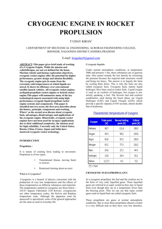
  • 1. CRYOGENIC ENGINE IN ROCKET PROPULSION T UDAY KIRAN1 1-DEPARTMENT OF MECHANICAL ENGINEERING, AURORAS ENGINEERING COLLEGE, BHONGIR, NALGONDA DISTRICT,ANDHRA PRADESH E-mail: kinguday9@gmail.com ABSTRACT–This paper gives brief study of working of a Cryogenic Engine. While the mission and vehicleDesigns, are not yet defined for the lunar, Martian robotic and human exploration objectives, cryogenic rocket engines offer the potential for higher performance, greater design and mission flexibility. The cryogenic engine gets its name from the extremely cold temperatures at which liquids are stored. It shows its efficiency over conventional satellite launch vehicles. All cryogenic rocket engines areliquid-propellant rocket engines or hybrid rocket engine.This paper will summarize many of the key technological aspects associated with using high- performance cryogenic liquid propellant rocket engine systems and components. This paper is classified into two areas, the first area describes about the history, principle, components and working, Where’ as the second area discuss about cryogenic fuels, advantages, disadvantages and applications of the cryogenic engine. Historically, cryogenic rocket engines have not been used for in-space applications due to their additional complexity, the mission need for high reliability. Currently only the United States, Russia, China, France, Japan and India have mastered cryogenic rocket technology. INTRODUCTION Propulsion : It is means of creating force leading to movement. Propulsion is of two types, • Translational (linear, moving faster or slower) • Rotational (turning about an axis) What is Cryogenics? Cryogenics is a branch of physics concerned with the production of very low temperatures and the effects of these temperatures on different substances and materials. The temperatures studied in cryogenics are those below - 243.67 degrees Fahrenheit (120 Kelvin). cryogenicists use other temperature scales, the Kelvin and Rankine temperature scale. Although the apparatus used for spacecraft is specialized, some of the general approaches are the same as used in everyday life. Cryogenic liquids: Under normal atmospheric conditions, at temperature 300k and pressure 1 bar, these substances are in gaseous state. One cannot remedy the low density by increasing the pressure because the required tank structures would end being too heavy. The answer is to liquefy the fuels by cooling them down. This is why the fuels are also called cryogenic fuels. Cryogenic fuels, mainly liquid hydrogen, have been used as rocket fuels. Liquid oxygen is used as an oxidizer of hydrogen, but oxygen is not, strictly speaking, a fuel. The favorite fuel and oxidizer combination used during the boost phase are Liquid Hydrogen (LH2) and Liquid Oxygen (LOX) which provide a specific impulse of 445 seconds, almost double that of hydrazine. CRYOGENIC FUELS/PROPELLANT: In a cryogenic propellant, the fuel and the oxidizer are in the form of very cold, liquefied gases. These liquefied gases are referred to as super cooled as they stay in liquid form even though they are at a temperature lower than the freezing point. Thus we can say that super cooled gases used as liquid fuels are called cryogenic fuels. These propellants are gases at normal atmospheric conditions. But to store these propellants aboard a rocket is a very difficult task as they have very low densities.
  • 2. Hence extremely huge tanks will be required to store the propellants. Thus by cooling and compressing them into liquids, we can vastly increase their density and make it possible to store them in large quantities in smaller tanks. Cryogenic Engine Introduction What is Cryogenic rocket engine? A cryogenic rocket engine is a rocket engine that uses a cryogenic fuel or oxidizer, that is, its fuel or oxidizer (or both) is gases liquefied and stored at very low temperatures. Notably, these engines were one of the main factors of the ultimate success in reaching the Moon by the Saturn V rocket. when powerful rocket engines were first considered by the German, American and Soviet engineers independently, all discovered that rocket engines need high mass flow rate of both oxidizer and fuel to generate a sufficient thrust. Hypothetically, if propellants had been stored as pressurized gases, the size and mass of fuel tanks themselves would severely decrease rocket efficiency. Therefore, to get the required mass flow rate, the only option was to cool the propellants down to cryogenic temperatures (below −150 °C, −238 °F), converting them to liquid form. Hence, all cryogenic rocket engines are also, by definition, either liquid-propellant rocket engines or hybrid rocket engines. History: The use of liquid fuel for rocket engines was considered as early as the beginning of 20th century. The Russian K.E.Ziolkowsky, the American H.Goddard and the German-Romanian H.Oberth worked independently on the problems of spaceflight and soon discovered that in order to succeed, rockets with high mass-flow were mandatory. However it was not later until these pioneers made their attempts, the first big liquid powered rocket the German A-4 became reality in the mid-forties. This rocket became successful as the V-2 weapon. Liquid oxygen was used as the oxidizer and ethyl alcohol as the fuel which gave the rocket more than 300KN of thrust. It`s range was 300km. As the development of rocket engines continued, higher thrust levels were achieved when liquid oxygen and liquid hydrocarbon were used as fuel. This allowed the construction of the first intercontinental rocket with a range of more than 10,000km. In the sixties, the steadily increasing payload weights and the corresponding demand for more thrust of the launcher lead to the use of liquid hydrogen for the Centaur upper stage. At the peak of this development was the US Space Shuttle Main Engine (SSME). Principle: The principle of rocket propulsion depends on the following two laws: - (i) Newton 's third law of motion (ii) Law of conservation of momentum The motion of a rocket is an interesting application of Newton’s third law of motion & momentum principle. The rocket expels a jet of hot gases from its tail. This is say, an action force. The jet of hot gases exerts a force on the rocket, propelling it forward; this is the reaction force. From the momentum point of view, the hot gases acquire momentum in the backward direction & the rocket acquires an equal amount of momentum in the forward direction. Propellants are used to provide thrust to the rockets. These propellants on burning produces large amount of gas, which are allowed to pass through nozzle. On passing through the nozzle, high pressure is generated i.e. gas comes out with high pressure. Now to increase the thrust, one basic property is used while designing the nozzle. The neck of the nozzle is kept very small as compared to the body of the rocket. So the pressure of the gas increases and so does the velocity. Thus high thrust is achieved. Tsiolkovsky Rocket Equation: The Tsiolkovsky rocket equation, or ideal rocket equation, describes the motion of vehicles that follow the basic principle of a rocket, a device that can apply acceleration to itself (a thrust) by expelling part of its mass with high speed and move due to the conservation of momentum. www.hearlihy.co
  • 3. where: is the initial total mass, including propellant, is the final total mass, is the effective exhaust velocity ( where is the specific impulse expressed as a time period and is Standard Gravity), is delta-v - the maximum change of speed of the vehicle (with no external forces acting) Specific Impulse: Specific impulse (usually abbreviated Isp) is a way to describe the efficiency of rocket and jet engines. It represents the force with respect to the amount of propellant used per unit time. Specific impulse is a measure or engine performance. Isp= Thrust / Weight flow rate of propellants. LIMITATIONS IN SLVs : where: Fthrust is the thrust obtained from the engine, in newtons (or poundals). Isp is the specific impulse measured in seconds. is the mass flow rate in kg/s (lb/s), which is negative the time-rate of change of the vehicle's mass since propellant is being expelled. G0 is the acceleration at the Earth's surface, in m/s² (or ft/s²). Components: The major components of a cryogenic rocket engine are: Combustion Chamber (thrust chamber) Pyrotechnic Igniter Fuel Injector Fuel Cryopumps, Oxidizer Cryopumps, Gas Turbine, Cryo Valves, Regulators, Fuel Tanks, Rocket Engine Nozzle. In terms of feeding propellants to combustion chamber, cryogenic rocket engines (or, generally, all liquid- propellant engines) work in either an expander cycle, a gas-generator cycle, a staged combustion cycle, or the simplest pressure-fed cycle. The cryopumps are always turbopumps powered by a flow of fuel through gas turbines. Looking at this aspect, engines can be differentiated into a main flow or a bypass flow configuration. In the main flow design, all the pumped fuel is fed through the gas turbines, and in the end injected to the combustion chamber. In the bypass configuration, the fuel flow is split; the main part goes directly to the combustion chamber to generate thrust, while only a small amount of the fuel goes to the turbine. PROPELLANTS SPECIFIC IMPULSE SOLID PROPELLANTS 265 s EARTH STATIONARY LIQUID PROPELLANTS 285 s CRYOGENIC PROPELLANTS 450 s
  • 4. Gas generator cycle: Expander cycle: Staged combustion cycle: Working: Cryogenic Engines are rocket motors designed for liquid fuels that have to be held at very low "cryogenic" temperatures to be liquid – they would otherwise be gas at normal temperatures. Typically Hydrogen and Oxygen are used which need to be held below 20°K (-423°F) and 90°K (-297°F) to remain liquid. The engine components are also cooled so the fuel doesn't boil to a gas in the lines that feed the engine. The thrust comes from the rapid expansion from liquid to gas with the gas emerging from the motor at very high speed. The energy needed to heat the fuels comes from burning them, once they are gasses. Cryogenic engines are the highest performing rocket motors. One disadvantage is that the fuel tanks tend to be bulky and require heavy insulation to store the propellant. Their high fuel efficiency, however, outweighs this disadvantage. Air moving around the vehicle is used to heat liquid nitrogen to a boil. Once it boils, it turns to gas in the same way that heated water forms steam in a steam engine. A rocket like the Ariane 5 uses oxygen and hydrogen, both stored as a cryogenic liquid, to produce its power. The liquid nitrogen, stored at -320 degrees Fahrenheit, is vaporized by the heat exchanger. Nitrogen gas formed in the heat exchanger expands to about 700 times the volume of its liquid form. This highly pressurised gas is then fed to the expander, where the force of the nitrogen gas is converted into mechanical power. Liquid-fuelled engine: Propellant: LOX / Liquid hydrogen The engines burn liquid hydrogen and liquid oxygen from the Space Shuttle external tank. They are used for propulsion during its ascent, in addition to the two more powerful solid rocket boosters and partly the Orbital Maneuvering System. Each engine can generate almost 1.8 meganewtons (MN) or 400,000lbf of thrust at liftoff. The engines are capable of generating a specific impulse Isp) of 453 seconds in a vacuum, or 363 seconds at sea level (exhaust velocities of 4440 m/s and 3560 m/s respectively). Overall, a space shuttle main engine weighs approximately 3.2 t (7,000 lb). The engines are removed after every flight and taken to the Space Shuttle Main Engine Processing Facility (SSMEPF) for inspection and replacement of any necessary components. The Space Shuttle's rocket engines are
  • 5. capable of operating at extreme temperatures. The liquid hydrogen fuel is stored at −253 degrees Celsius (−423degrees Fahrenheit). However, when burned with liquid oxygen, the temperature in the combustion chamber reaches 3,300 °C (6,000 °F), higher than the boiling point of iron. Each engine consumes 1,340 liters (340 gallons)of propellant per second. If the engine pumped water instead of liquid oxygen and liquid hydrogen, an average-sized swimming pool could be drained in 75seconds - or 25 seconds for the sum of the three used for the space shuttle launch. The engines perform as follows: Fuel and oxidizer from the external tank enters the orbiter at the orbiter/external tank umbilical disconnect and then the orbiter's main propulsion system feed lines. There the fuel and oxidizer each branch out into three parallel paths, to each engine. In each branch, prevalves must be opened to permit flow to the low-pressure fuel or oxidizer turbopump Oxidizer system: The Low Pressure Oxidizer Turbopump (LPOTP) is an axial-flow pump driven by a six-stage turbine powered by liquid oxygen. It boosts the liquid oxygen's pressure from 0.7 to 2.9 MPa (100 to 420 psi). The flow from the LPOTP is supplied to the High-Pressure Oxidizer Turbopump (HPOTP). During engine operation, the pressure boost permits the High Pressure Oxidizer Turbine to operate at high speeds without cavitating. The LPOTP operates at approximately 5,150 rpm. The LPOTP, which measures approximately 450 by 450 mm (18 by 18 inches), is connected to the vehicle propellant ducting and supported in a fixed position by the orbiter structure. The HPOTP consists of two single-stage centrifugal pumps (a main pump and a pre-burner pump) mounted on a common shaft and driven by a two-stage, hot-gas turbine. The main pump boosts the liquid oxygen's pressure from 2.9 to 30 MPa (420 to 4,300 psi) while operating at approximately 28,120 rpm. The HPOTP discharge flow splits into several paths, one of which is routed to drive the LPOTP turbine. Another path is routed to and through the main oxidizer valve and enters into the main combustion chamber. Another small flow path is tapped off and sent to the oxidizer heat exchanger. The liquid oxygen flows through an anti- flood valve that prevents it from entering the heat exchanger until sufficient heat is present to convert the liquid oxygen to gas. The heat exchanger utilizes the heat contained in the discharge gases from the HPOTP turbine to convert the liquid oxygen to gas. The gas is sent to a manifold and is then routed to the external tank to pressurize the liquid oxygen tank. Another path enters the HPOT second-stage preburner pump to boost the liquid oxygen's pressure from 30 to 51 MPa (4,300 psia to 7,400 psia). It passes through the oxidizer preburner oxidizer valve into the oxidizer preburner and through the fuel preburner oxidizer valve into the fuel preburner. The HPOTP measures approximately 600 by 900 mm (24 by 36 inches). It is attached by flanges to the hot-gas manifold. The HPOTP turbine and HPOTP pumps are mounted on a common shaft. Mixing of the fuel-rich hot gas in the turbine section and the liquid oxygen in the main pump could create a hazard. To prevent this, the two sections are separated by a cavity that is continuously purged by the MPS engine helium supply during engine operation. Two seals minimize leakage into the cavity. One seal is located between the turbine section and the cavity, and the other is between the pump section and cavity. Loss of helium pressure in this cavity results in an automatic engine shutdown. Hydrogen fuel system: Fuel enters the orbiter at the liquid hydrogen feed line disconnect valve, then flows into the orbiter liquid hydrogen feed line manifold and branches out into three parallel paths to each engine. In each liquid hydrogen branch, a prevalve permits liquid hydrogen to flow to the low-pressure fuel turbopump when the prevalve is open. The Low Pressure Fuel Turbopump (LPFTP) is an axial- flow pump driven by a two-stage turbine powered by gaseous hydrogen. It boosts the pressure of the liquid hydrogen from 30 to 276 psia (0.2 to 1.9 MPa) and supplies it to the High-Pressure Fuel Turbopump (HPFTP). During engine operation, the pressure boost provided by the LPFTP permits the HPFTP to operate at high speeds without cavitating. The LPFTP operates at approximately 16,185 rpm. The LPFTP is approximately 450 by 600 mm (18 by 24 inches). It is connected to the vehicle propellant ducting and is supported in a fixed position by the orbiter structure 180 degrees from the LPOTP. The HPFTP is a three-stage centrifugal pump driven by a two-stage, hot-gas turbine. It boosts the pressure of the liquid hydrogen from 1.9 to 45 MPa (276 to 6,515 psia). The HPFTP operates at approximately 35,360 rpm. The discharge flow from the turbopump is routed to and through the main valve and then splits into three flow paths. One path is through the jacket of the main combustion chamber, where the hydrogen is used to cool the chamber walls. It is then routed from the main combustion chamber to the LPFTP, where it is used to drive the LPFTP turbine. A small portion of the flow from the LPFTP is then directed to a common manifold from all three engines to form a single path to the external tank to maintain liquid hydrogen tank pressurization. The remaining hydrogen passes between the inner and outer walls to cool the hot-gas manifold and is discharged into the main combustion chamber. The second hydrogen flow path from the main fuel valve is through the engine nozzle (to cool the nozzle). It then joins the third flow path from the chamber coolant valve. The combined flow is then directed to the fuel and oxidizer preburners. The HPFTP is approximately 550 by 1100 mm (22 by 44 inches). It is attached by flanges to the hot-gas manifold. Pre-burners and thrust control system: The oxidizer and fuel preburners are welded to the hot- gasmanifold. The fuel and oxidizer enter the preburners and are mixed so that efficient combustion can occur. The augmented spark igniter is a small combination chamber located in the center of the injector of each preburner. The two dual-redundant spark igniters, which
  • 6. are activated by the engine controller, are used during the engine start sequence to initiate combustion in each preburner. They are turned off after approximately three seconds because the combustion process is then self- sustaining. The preburners produce the fuel-rich hot gas that passes through the turbines to generate the power to operate the high-pressure turbopumps. The oxidizer preburner's outflow drives a turbine that is connected to the HPOTP and the oxidizer preburner pump. The fuel preburner's outflow drives a turbine that is connected to the HPFTP. The speed of the HPOTP and HPFTP turbines depends on the position of the corresponding oxidizer and fuel preburner oxidizer valves. These valves are positioned by the engine controller, which uses them to throttle the flow of liquid oxygen to the preburners and, thus, control engine thrust. The oxidizer and fuel preburner oxidizer valves increase or decrease the liquid oxygen flow, thus increasing or decreasing preburner chamber pressure, HPOTP and HPFTP turbine speed, and liquid oxygen and gaseous hydrogen flow into the main combustion chamber, which increases or decreases engine thrust, thus throttling the engine. The oxidizer and fuel preburner valves operate together to throttle the engine and maintain a constant 6-1 propellant mixture ratio. The main oxidizer valve and the main fuel valve control the flow of liquid oxygen and liquid hydrogen into the engine and are controlled by each engine controller. When an engine is operating, the main valves are fully open. Cooling control system: A coolant control valve is mounted on the combustion chamber coolant bypass duct of each engine. The engine controller regulates the amount of gaseous hydrogen allowed to bypass the nozzle coolant loop, thus controlling its temperature. The chamber coolant valve is 100 % open before engine start. During engine operation, it will be 100 % open for throttle settings of 100 to 109 % for maximum cooling. For throttle settings between 65 to 100 %, its position will range from 66.4 to 100 % open for reduced cooling. Combustion chamber and nozzle Each engine main combustion chamber receives fuel-rich hot gas from a hot-gas manifold cooling circuit. The gaseous hydrogen and liquid oxygen enter the chamber at the injector, which mixes the propellants. A small augmented spark igniter chamber is located in the center of the injector. The dual-redundant igniter is used during the engine start sequence to initiate combustion. The igniters are turned off after approximately three seconds because the combustion process is self-sustaining. The main injector and dome assembly is welded to the hot- gas manifold. The main combustion chamber also is bolted to the hot-gas manifold. The inner surface of each combustion chamber, as well as the inner surface of each nozzle, is cooled by liquid hydrogen flowing through brazed stainless steel tube- wall coolant passages. The nozzle assembly is a bell- shaped extension bolted to the main combustion chamber. The nozzle is 2.9 m (113 inches) long, and the outside diameter of the exit is 2.4 m (94 inches). A support ring welded to the forward end of the nozzle is the engine attach point to the orbiter-supplied heat shield. Thermal protection is necessary because of the exposure portions of the nozzles experience during the launch, ascent, on-orbit and entry phases of a mission. The insulation consists of four layers of metallic batting covered with a metallic foil and screening.For a nozzle able to run at sea level, the SSME nozzle has an unusually large expansion ratio (about 77) for the chamber pressure. A nozzle that large would normally undergo flow separation of the jet from the nozzle which would cause control difficulties and could even mechanically damage the vehicle. Instead the Rocketdyne engineers varied the angle of the nozzle, reducing it near the exit. This raises the pressure just around the rim to between 4.6 and 5.7 psi, and prevents flow separation. The inner part of the flow is at much lower pressure, around 2 psi or less. Main valves: The five propellant valves on each engine (oxidizer preburner oxidizer, fuel preburner oxidizer, main oxidizer, main fuel, and chamber coolant) are hydraulically actuated and controlled by electrical signals from the engine controller. They can be fully closed by using the MPS engine helium supply system as a backup actuation system. The main oxidizer valve and fuel bleed valve are used after shutdown. The main oxidizer valve is opened during a propellant dump to allow residual liquid oxygen to be dumped overboard through the engine, and the fuel bleed valve is opened to allow residual liquid hydrogen to be dumped through the liquid hydrogen fill and drain valves overboard. After the dump is completed, the valves close and remain closed for the remainder of the mission. Controller: An important innovation was the inclusion of an integrated controller in the engine itself: the SSME controller. This digital computer (originally composed with two redundant Honeywell HDC-601 computers, and
  • 7. later replaced with a system with two redundant Motorola 68000 processors) has two tasks: control the engine and its burning process, and check itself. This arrangement greatly simplified the wiring between the engine and the shuttle, because all the sensors and actuators are connected directly to it. Using a dedicated system also simplified the software and improved its reliability. Two independent computers, A and B, form the controller, giving redundancy to the system. The failure of the system A will automatically switch to the system B without impeding operational capabilities; the failure of the system B will provide a graceful shutdown of the engine. Advantages: Storable liquid stages of PSLV and GSLV engines used presently release harmful products to the environment. The trend worldwide is to change over to eco-friendly propellants. Liquid engines working with cryogenic propellants (liquid oxygen and liquid hydrogen) and semi cryogenic engines using liquid oxygen and kerosene are considered relatively environment friendly, non-toxic and non corrosive. In addition, the propellants for semi- cryogenic engine are safer to handle & store. It will also reduce the cost of launch operations. This advanced propulsion technology is now available only with Russia and USA. India is capable to meet existing mission requirements. The semi cryogenic engine will facilitate applications for future space missions such as the Reusable Launch Vehicle, Unified Launch Vehicle and vehicle for interplanetary missions. High Energy per unit mass: Propellants like oxygen and hydrogen in liquid form give very high amounts of energy per unit mass due to which the amount of fuel to be carried aboard the rockets decreases. Clean Fuels: Hydrogen and oxygen are extremely clean fuels. When they combine, they give out only water. This water is thrown out of the nozzle in form of very hot vapour. Thus the rocket is nothing but a high burning steam engine Economical : Use of oxygen and hydrogen as fuels is very economical, as liquid oxygen costs less than gasoline. Disadvantages:  Boil off Rate.  Highly reactive gases.  Leakage.  Hydrogen Embrittlement .  Zero Gravity conditions. Applications: Cryogenic engines are the highest performing rocket motors and are widely used in Aerospace and defense applications. The next generation of the Rocket Engines:  All rocket engines burn their fuel to generate thrust. If any other engine can generate enough thrust, that can also be used as a rocket engine  There are a lot of plans for new engines that the NASA scientists are still working with. One of them is the “ Xenon ion Engine” . This engine accelerate ions or atomic particles to extremely high speeds to create thrust more efficiently. NASA's Deep Space-1 spacecraft will be the first to use ion engines for propulsion.  There are some alternative solutions like Nuclear thermal rocket engines, Solar thermal rockets, the electric rocket etc.  We are looking forward that in the near future there will be some good technology to take us into space  Interplanetary travel will require advanced forms of propulsion technology: 1. Antimatter 2. Nuclear fusion 3. Non-rocket methods Conclusion: Present programs relate to Cryogenic Upper Stages for launch vehicles. Semi-cryogenicengines, Hypergolic engines are being developed. References: 1. http://en.wikipedia.org/wiki/Spacecraft_propul sion 2. http://en.wikipedia.org/wiki/Cryogenic_engine 3. http://en.wikipedia.org/wiki/Cryogenic_fuel 4. http://en.wikipedia.org/wiki/Liquid- propellant_rocket 5. http://www.nasa.gov/mission_pages/constellati on/main/index2.html 6. http://en.wikipedia.org/wiki/Ion_thruster.
  • 8. .