SlideShare a Scribd company logo
1 of 91
OIL & GAS
        EXPLORATION, PRODUCTION AND
               OPTIMIZATION


                                              Great Lakes Institute Of
                                              Energy Management
                                              Gurgaon
Image Sources:ABB Oil and Gas Production Handbook
AGENDA
•   Geophysical data
•   Rigs, Drilling,Casing & Cementing
•   Wireline Logging
•   Completion of well(Well head, Christmas Tree)
•   Production, Well Testing
•   Decision Making
•   EOR
•   Case Study
•   Abandonment of a well
GEOPHYSICAL DATA


   Riches in Rocks


Image Sources:ABB Oil and Gas Production Handbook, Schlumberger Western
Geco Public Site.
RIGS


 • Land Rigs
 • Jack up Rigs
 • Drill Ships
Image Sources:ABB Oil and Gas Production
              Handbook,Schlumberger
Videos:From You Tube
Different Types Of Rigs
• Submersible
This is a drilling structure which is used in relatively shallow
water, usually 80 feet or less. It is towed to its location where it is
submerged until it sits on the bottom. This submerging serves as its
mooring system, although anchors may also be used.


• Semi Submersible
This rig has the hull design of a catamaran and is either towed or self-
propelled. A semi-submersible can also be dynamically positioned or it
can use anchors. When the rig is on location, it is ballasted down, in
about the same way a submarine submerges, fifty feet or so to give it
stability. Semis are heavy-duty rigs and are designed for adverse
weather conditions.


Image Sources:Google Images and Schlumberger.
• Drill Ship
A drillship can be one of two types:
1) It can be a ship which was designed and built to be a drilling vessel; or
2) A drillship can be an older vessel which has been refitted with drilling equipment.
Drill ships are self-propelled, carrying a complete ship's crew while underway, as well as
a crew of drilling personnel. Drill ships are moored either by the standard anchoring
system or by dynamic positioning of the vessel. Dynamic positioning is the use of a
computer-operated inboard thruster system which keeps the vessel on location without
the use of anchors. This arrangement allows vessels to drill in ultra-deep water.


• Jack up
Jack-ups are towed to their location where rig personnel use heavy machinery to
jack the legs down into the water until they are on the ocean floor. When this is
competed, the platform containing the work area rises above the water. After the
platform his risen about 50 feet out of the water, the rig is ready to begin drilling.
Jack-up rigs are limited to a water depth of about 300 feet or less.


Image Sources: Schlumberger and Google Images
• Barge
This is used to make extremely heavy lifts (The record to-date is 4,400 tons!) or to lay
underwater pipelines. When these lifts are being made, there are usually a lot of
support personnel on board (up to 200) including welders, electricians, riggers,
operators, etc. Derrick barges can be either self-propelled or towed.


 Image Sources: Google Images
PLATFORMS
•     Fixed Platform
•     Complaint Tower
•     Sea Star
•     Floating Production Systems
•     Tension Leg Platforms
•     Subsea Systems
•     Spar Platform


    Source: www.naturalgas.org
FIXED PLATFORM
Used
In shallower water, if it is possible to physically attach a platform to the sea
floor.

How
The 'legs' are constructed with concrete or steel, extending down from the
platform, and fixed to the seafloor with piles.

Weight of the legs and seafloor platform is substantial, so they do not have to
be physically attached to the seafloor, but instead simply rest on their own
mass.

Many possible designs for these fixed, permanent platforms.

Advantage
The main advantages of these types of platforms are their stability, as they are
attached to the sea floor there is limited exposure to movement due to wind
and water forces.

Limitation
These platforms cannot be used in extremely deep water, not economical to
build legs that long.
  Source: www.naturalgas.org
COMPLAINT TOWER
Much like fixed platforms. Each consists of a narrow tower, attached to
a foundation on the seafloor and extending up to the platform
Advantages
The tower is flexible, as opposed to the relatively rigid legs of a fixed
platform. This flexibility allows it to operate in much deeper water than
fixed platforms
Disadvantages
The stability is far lesser than the fixed platforms. They get easily
affected by rough weather and winds.


  Source: www.naturalgas.org
SEASTAR PLATFORMS
•   Seastar Platforms are similar to tension leg platforms.
•   The platform consists of a floating rig, A lower hull is
    filled with water when drilling,.
• Seastar platforms also incorporate the tension leg
    system employed in larger platforms. Tension legs are
    long, hollow tendons that extend from the seafloor to
    the floating platform.
Advantages
Seastar platforms are typically used for smaller deep-water
reservoirs, when it is not economical to build a larger
platform. They can operate in water depths of up to 3,500
feet.


    Source: www.naturalgas.org
TENSION LEG PLATFORM
Tension leg platform is similar to sea star platform. But unlike
in sea star, the tension legs don't go all the way to the sea
floor. The structure is held in a fixed position by tensioned
tendons, which provide for use of the TLP in a broad water
depth range up to about 2000m. The tendons are constructed
as hollow high tensile strength steel pipes that carry the spare
buoyancy of the structure and ensure limited vertical motion.
Due to this the platform experiences more horizontal motion
due to the jerks from the rough weather. This platform allows
drilling at an amazing depth of 7000 feet. A variant is Seastar.


 Source: www.naturalgas.org
SUBSEA SYSTEM
• This platform has features from all the platforms that we discussed earlier. are
  wells located on the sea floor, as opposed to at the surface. Like in a floating
  production system, the petroleum is extracted at the seafloor, and then can be
  'tied-back' to an already existing production platform or even an onshore facility .
• It is used to drill at depths of 7000 and above. The drilling apparatus is fixed on the
  sea bed and the drilled oil is sent up with the help of risers.


 Source: www.naturalgas.org
SPAR PLATFORM
The SPAR consists of a single tall floating cylinder hull, supporting a fixed deck. The cylinder
however does not extend all the way to the seafloor, but instead is tethered to the bottom by a
series of cables and lines.

SPAR is not an acronym, but refers to its likeness with a ship’s spar. Spars can support dry
completion wells, but is more often used with subsea wells. Subsea production systems are
wells located on the sea floor, as opposed to at the


 Source: www.naturalgas.org
References
•   8 References
•   Web on line sources and references that has been used in compiling this document:
•   · Schlumberger oilfield glossary:
•   http://www.glossary.oilfield.slb.com/default.cfm
•   · Norsk Hydro, Njord Main Process and Oil Process Description.
•   http://www.hydro.com/en/our_business/oil_energy/production/oil_gas_nor
•   way/njord.html
•   · Wikipedia http://en.wikipedia.org/wiki/Main_Page
•   · Oklahoma State, Marginal Well Commission, Pumper’s Manual
•   http://www.marginalwells.com/MWC/pumper_manual.htm
•   · Natural Gas Supply Association. See Natural Gas - From Wellhead to
•   Burner Tip
•   http://www.naturalgas.org/index.asp
•   · US geological survey: http://www.usgs.gov/
•   · US department of energy: http://www.doe.gov/
•   · NORSOK standards, Standards Norway (SN),
•   http://www.standard.no/imaker.exe?id=244
•   · UK Offshore Operators Association (UKOOA)
•   http://www.oilandgas.org.uk/issues/storyofoil/index.htm
•   · National Biodiesel Board http://www.biodiesel.org/
•   · PBS – Public Broadcasting Service - Extreme Oil
•   http://www.pbs.org/wnet/extremeoil/index.html
•   · http://www.priweb.org/ed/pgws/history/pennsylvania/pennsylvania.html
COST COMPARISION
      FLOATING RIGS

      Rig Type                Rigs Working             Total Rig Fleet              Average Day Rate

      Drillship < 4000’ WD                    6 rigs                       8 rigs                $241000

      Drillship 4000’ + WD                   48 rigs                      61 rigs                $462000

      Semisub < 1500’ WD                     10 rigs                      17 rigs                $241000

      Semisub 1500’ + WD                     63 rigs                      87 rigs                $302000

      Semisub 4000’ + WD                     85 rigs                     105 rigs                $418000


Source: rigzone public site
JACKUP RIGS
       Rig Type               Rigs Working              Total Rig Fleet              Average Day Rate
       Jackup IC < 250’ WD                    32 rigs                      53 rigs                $68000
       Jackup IC 250’ WD                      37 rigs                      63 rigs                $80000
       Jackup IC 300’ WD                      94 rigs                     131 rigs                $89000
       Jackup IC 300’ + WD                   122 rigs                     151 rigs               $144000
       Jackup IS < 250’ WD                     5 rigs                      53 rigs                $68000
       Jackup IS 250’ WD                       7 rigs                      53 rigs                $68000
       Jackup IS 300’ WD                       2 rigs                      53 rigs                $68000
       Jackup IS 300’ + WD                     1 rigs                      53 rigs                $68000
       Jackup MC < 200’ WD                     2 rigs                      53 rigs                $68000
       Jackup MC 200’ + WD                    12 rigs                      28 rigs                $46000
       Jackup MS < 200’ WD                     2 rigs                       2 rigs                      -
       Jackup MS 200’ + WD                     4 rigs                      19 rigs                $43000


Source: rigzone public site
OTHER OFFSHORE RIGS

      Rig Type                Rigs Working              Total Rig Fleet              Average Day Rate

      Drill Barge < 150’ WD                   18 rigs                      39 rigs                      -

      Drill Barge 150’ WD                      6 rigs                       9 rigs                      -

      Inland Barge                            27 rigs                      74 rigs                 $47000

      Platform Rg                            144 rigs                     250 rigs                 $37000

      Submersible                              0 rigs                       5 rigs                      -

      Tender                                  23 rigs                      32 rigs                $132000


Source: rigzone public site
Classes of Oil well
• Oil wells can generally be grouped into two
  categories:
   – Exploration or ‘Wild Cat’
     • A potential ‘oil-field’ never drilled before – could be no oil

   – Development
       Oil field already present – simply extracting more oil
DRILLING
  Horizontal Drilling
  It is an enhanced oil recovery
  (EOR) or gas recovery method .

  Casing
  Three different types
  Surface
  Intermediate
  Production

  Blow Out Preventer(BOP)


Videos Source: You Tube
Image Sources: Google Images
BOP
 • Subsea Blow-out Preventor
   (BOP) stacks are specially
   designed to operate under
   water at great depths.
 • They are located on the sea
   bed, rather than above water
   on the rig.
 • Subsea BOPs are used only
   on floating rigs.
 • They are a very important
   safety device to prevent the
   well ‘blowing’ oil

Source: ABB handbook
WIRELINE LOGGING

 • Geological logs
  visual inspection of samples brought to
 the surface
 • Geophysical logs
 physical measurements made by
 instruments lowered into the hole .
 • Well logging is done during all phases
   of a well's development;
   drilling, completing, producing and
   abandoning.

Image Source: Schlumberger
Video Source: You Tube
Cementing
• Two processes – Wet and Dry
• Sets through a chemical
   does not need air to set
• Very complex chemistry
   Contains silica, alumina and iron oxide
• Grind the resulting product to a fine powder
                                                           Dry
Cement Recipes
A ‘recipe’ – a specific combination of chemicals mixed
with neat cement and water to achieve a desired
slurry/set cement.
Many different additives in use
     • accelerators, retarders, dispersants, fluid-loss,
        extenders
     • Schlumberger uses ‘D’ codes to designate an
        additive
                                                                 Wet
  Source: Schlumberger
Objectives of Cement Job
• There are three main objectives:
  – Provide complete isolation of zones
  – Support the casing
  – Protect casing string


 Image Source: Schlumberger
Completion
Early wells were drilled in very shallow reservoirs which were sufficiently consolidated
to prevent caving. As deeper wells were drilled, the problems associated with surface
water prompted the use of a casing or conductor to isolate water and prevent caving
of the wellbore walls. Further development of this process led to fully cased wellbores
in which the interval of interest is perforated.
Modern completions are now commonly undertaken in deep, hot and difficult
conditions. In all cases, achieving the completion and eventual production objectives
are a result of careful planning and preparation.

Completion Types
The most common criteria for the classification of completions include the following
• Open-hole or cased hole, horizontal completion
• Producing zones, i.e., single zone or multiple zone production
• Production method, i.e., natural flowing or artificially induced production (Artificial
   Lift)
• Open Hole Completion
Barefoot completions are only feasible in reservoirs
with sufficient formation strength to prevent caving or
sloughing. In such completions there are no means of
selectively producing or isolating intervals within the
reservoir or open hole section. The production casing
or liner is set and cemented in the reservoir cap
rock, leaving the wellbore through to the reservoir
open.
The use of open hole completions is now restricted
primarily to some types of
horizontal wells and to wells where formation damage
from (air drilling) drilling fluids is severe.
To prevent an unstable formation from collapsing and
plugging the wellbore, slotted screen or perforated
liners may be placed across the open


   Source: Schlumberger
• Cased Hole Completions
Modern perforating charges and techniques are
designed to provide a clear perforation tunnel
through the damaged zone surrounding the wellbore.
This provides access to the undamaged
deformation, allowing the reservoir to be produced
to its full capability.
Cased and cemented wells generally require less
complex pressure control procedures during the early
stages of installing the completion components


• Natural Flowing
Wells completed in reservoirs which are capable of
producing without assistance are typically more
economic to produce.
In general, naturally flowing wells require less
complex downhole components and equipment. In
addition, the long-term reliability and longevity of
the downhole components is generally better than
that of pumped completions.
 Source: Schlumberger
• Artificial Completions
All pumped, or artificially lifted, completions require the placement of specialized
downhole components. Such components are electrically or mechanically operated, or
are precision engineered devices. These features often mean the longevity or reliable
working life of an artificial lift completion is limited. In addition, the maintenance or
periodic workover requirements will generally be greater than that of a naturally
flowing completion.

•   Artificial Lift Methods
•   Gas lift
•   Electric submersible pump
•   Plunger lift
•   Hydraulic or Jet Pump
•   Variable Cavity Pump (VCP)
•   Hydraulic or Jet pump
•   Progressive cavity pump (PCP)
COMPLETION
 Completion Tubing
 Completion Assembly
 1. Packer
 2. Permanent Downhole Gauge
 3. Safety Valve
 4. Christmas Tree


Video Source: You Tube
Images Source: Google Images
WELL TESTING
Separator:
To separate different constituents of drawn
oil.
Flaring:
Burning the first few barrels.


Source: ABB Handbook
DECISION MAKING
• Factors affecting the decision making in E&P.
1. Reservoir Technological factors,
2. Economic factors.


Source: en.wikipedia.org
RESERVOIR TECHNOLOGICAL FACTORS
•    Pressure,
•    Temperature,
•    Porosity,
•    Permeability,
•    API Gravity,
•    Sulphur Content.


    Source: en.wikipedia.org
CRUDE OIL ANALYSIS


Source: Oil and Gas Production Handbook by ABB
PVT ANALYSIS


Source: Oil and Gas Production Handbook by ABB
POROSITY & SORTING


Source: Oil and Gas Production Handbook by ABB
POROSITY LEVEL IN RESERVOIRS


                                 POROSITY
Percentage of Pores                          Usage
  Less than 10%                    Poor, Productivity Doubtful.
     10 - 15%                                    Fair.
     15 - 25%         Good, the most common range in production reservoirs.
     Over 25%                          Excellent, but rare.


Source: Oil and Gas Production Handbook by ABB
POROSITY Vs PERMEABILITY


Source: Oil and Gas Production Handbook by ABB
PERMEABILITY LEVEL IN RESERVOIRS


                               Permeability
 Permeability Value                           Usage
        10 mD                                 Poor
       100 mD                             Fair to Good
      1000 mD                         Excellent, but rare.


Source: Oil and Gas Production Handbook by ABB
RELATIVE PERMEABILITY


Source: Oil and Gas Production Handbook by ABB
API GRAVITY


                   Ideal value of API Gravity is 10 to 70.


Source: Oil and Gas Production Handbook by ABB
SULPHUR CONTENT
   Standard fuel oil - Sulphur content rate should not exceed 4.5%
   Low Sulphur fuel oil - Sulphur content rate should not exceed 1.5%.

   Sweet crude oil has a sulphur content less than 0.5%.

   Anything more than 0.5% is sour.

Heavy crude is:
• harder to handle (it is two thick to pump easily through pipelines unless
  diluted with light crude)
• more expensive to refine to produce the most valuable petroleum
  products such as petrol, diesel and aviation fuel.
• Sweet crude is preferable to sour because it is also (like light crude) more
  suited to the production of the most valuable refined products.

 Source: en.wikipedia.org
ECONOMIC FACTORS

• Cost of benefit.

• Funds.

• Rate of Return.


Source: en.wikipedia.org
Cost Benefit Analysis
• Cost–benefit analysis (CBA) is a systematic
  process for calculating and comparing benefits
  and costs of a project for two purposes:
• A) to determine if it is a sound investment to dig
  a well (justification/feasibility),
• B) to see how it compares with alternate projects
  (ranking/priority assignment)
• It involves comparing the total expected cost of
  each option against the total expected benefits,
  to see whether the benefits outweigh the costs,
  and by how much.
 Source: en.wikipedia.org
FUNDS
• NPV (net present value)

• PVB (present value of benefits)

• PVC (present value of costs)

• BCR (benefit cost ratio) = PVB / PVC

• Net benefit = (PVB - PVC)

 Source: en.wikipedia.org
Rate of Return
• Rate of Return indicate cash flow from an
  investment(Oil Well) to the investor over a
  specified period of time, usually a year.
• ROR is a measure of investment
  profitability, not a measure of investment size.
• The higher the investment risk, the greater the
  potential investment return, and the greater
  the potential investment loss.
Source: en.wikipedia.org
PRODUCTION OPTIMIZATION
    Improving Productivity is a huge problem.
    Various Factors :
•   Operational Costs
•   Hardware Damage
•   Reservoir Performance
•   Environmental Requirements
•   Operational Difficulties


Source: Oil and Gas Production Handbook by ABB
Applications included in Production
             Optimization
• Flow line Control
To stabilize the Multiphase Flow in gathering systems, risers &
Flow lines.

• Well Control
To stabilize and Optimize gas lift and naturally flowing wells.

• Slug Management
It will help mitigate variations in Inflow impact.

• Well Monitoring System
Used to estimate the flow rates of Oil, Gas & Water from all
the individual wells in an Oil Field.
Source: Oil and Gas Production Handbook by ABB
ENHANCED OIL RECOVERY AND
       IMPROVED OIL RECOVERY
EOR:-
•It is the process that seek to improve the recovery
of hydrocarbon from a reservoir after the primary
and secondary production phase.
•Enhanced Oil Recovery is a generic term for
techniques for increasing the amount of crude
oil that can be extracted from an oil field. Using
EOR, 30-60 %, or more, of the reservoir's original
oil can be extracted compared with 20-
40% using primary and secondary recovery.
Improved Oil Recovery:-
• Any of various methods chiefly reservoir drive
   mechanism and enhanced recovery techniques,
   designed to improve the flow of hydrocarbons from
   the reservoir to the wellbore or to recover more oil
   after the primary and secondary methods(water- and
   gas floods).
Primary Oil Recovery:-
• This implies the initial production stage, resulted
   from the displacement energy naturally existing in a
   reservoir.
 Secondary Oil Recovery:-
• A recovery improvement process such as water
   flooding and gas flooding.
LIMITATIONS AND DISADVANTAGES OF
      PRIMARY AND SECONDARY RECOVERY
                  PROCESSES
• Rapid decrease in reservoir pressure – leads to
  low oil production rates and oil recovery (5 – 10
  % of original oil in place).
• Secondary recovery (water / gas injection) often
  does not yield a good recovery due to:
 - Reservoir heterogeneity
 -Unfavourable mobility ratio between oil and
  water
 - Water and gas coning problems
 - Low sweep efficiency
WHEN TO START EOR?
    A common procedure for determining the optimum
    time to start EOR process after water flooding
    depends on:-
•   Anticipated oil recovery
•   Fluid production rates
•   Monetary investment
•   Costs of water treatment and pumping equipment
•   Costs of maintenance and operation of the water
    installation facilities.
•   Costs of drilling new injection wells or converting
    existing production wells into injectors.
WHY EOR?
Oil and Gas market ripe for breakthrough-EOR Solution:-
• World oil consumption rate at 85 million barrel per day.
• 1/3 production increases over next 15 years to meet
   projected demand.
• Oil production faster, less expensive and with less
   disturbance to environment from existing wells.
• EOR can prolong life of oil field upto 30 years .
• There is significant oil in place in discovered reservoirs
   that will otherwise not be recovered.
• EOR can make an important contribution to world oil
   supply in the long term.
• EOR economics can be attractive.
WORLD OIL PRODUCTION FORECAST (IEA)
• 64 million b/d of capacity additions needed by
  2030.
• 5 million b/d is forecast to be supplied by EOR
  in 2030.
• 20 million b/d is from fields yet to be found.
• 33% recovery efficiency ->EOR target of 2.2
  trillion barrels in discovered fields.
A Boom of EOR Program:-
• Proven reserves
• Hard to get oil
• Demand outstripping supply
• Cost of finding new oil reservoir
• Political problems
• Environmental concern
Example-Occidental Chemical Co. maintains a
  very successful EOR program, producing
  approximately 350000 barrels of oil equivalent
  per day.
Business Benefits:-
• Optimize oil recovery with field proven flow
  and density solutions
• Simplify operations and reduce maintenance
  costs with reliable and accurate measurement
• Multi-variable output and process intelligence
  enable remote surveillance and reduced
  operator intervention
• Reduce chemical costs through accurate flood
  material allocation and dosage
EOR POTENTIAL
Opportunities:-
• Target resource for EOR applications is 6 trillion barrels, of
   the 9 trillion initially in place.
• Widespread application could far exceed the current
   forecasts.
• Chemical / polymer flooding has large unrealized
   potential.
• Both hydrocarbon and CO2 miscible flooding have large
   potential internationally.
• A significant resource exists in the offshore, as well as
   onshore .
• CO2 sequestration may provide an additional impetus and
  opportunity.
WHY EOR IS NEEDED NOW?
• Design and implementation of an EOR project takes time.
• After implementation (especially as a tertiary project) production
  response does not occur immediately.
                        EOR Project Time Line
EOR TECHNIQUES
1. Gas Injection
•   Carbon Dioxide Flooding
•   Miscible Solvent(LPG or Propane)
•   Enriched Gas Drive
•   High-Pressure Gas drive
•   Inert Gas( Nitrogen)
•   Flue Gas
Carbon Dioxide Flooding
• Commonly used approach.
• Aids recovery by reducing the viscosity of the
crude oil as the gas mixes with it.
• Air cannot be used to repressurize the
reservoir because the oil will quickly catch on
fire.
• Oil displacement by carbon dioxide
injection relies on the phase behaviour of the
mixtures of that gas and the crude, which are
strongly dependent on reservoir temperature,
pressure and crude oil composition.
Benefits of CO2 Flooding:-
• Injections of CO2 work with lighter gravities.
• Its production has been growing steadily, and
  volumes reached 240,000 barrels a day in
  2008, a tenfold increase from 28,000 barrels a
  day in 1986.
• WAG is frequently used in carbon dioxide
  flooding to increase sweep efficiency and
  decrease the need for expensive solvents.
Cost of CO2 Flooding:-
• Adding oil recovery methods adds to the cost
  of oil — in the case of CO2 typically between
  0.5-8.0 US$ per tonne of CO2.
• Onshore EOR has paid in the range of a net
  10-16 US$ per tonne of CO2 injected for oil
  prices of 15-20 US$/barrel.
• With oil prices at around 90 US$/barrel, the
  economic benefit is about 70 US$ per tonne
  CO2.
Benefits of Inert gas flooding:-
• Availability and low cost.
• Prevention of oil encroachment into the gas
  cap when gas cap is present.
• Higher recoveries compared to water drive in
  reservoirs having low permeability.
• Residual inert gas at abandonment rather
  than saleable natural gas.
• Reliability of the supply.
2. Chemical Flooding
• Alkaline Surfactant Polymer or Caustic
  flooding
• Polymer-augmented water flooding
• Surfactant flooding
  -Low tension water flooding
  -Micellar/Polymer(micro emulsion) flooding
Alkaline Surfactant Polymer Flooding
• ASP flooding is a form of chemical enhanced oil recovery (EOR) that
  can allow operators to extend reservoir pool life and extract
  incremental reserves currently inaccessible by conventional EOR
  techniques such as water flooding.
• Injection of diluted alkaline or caustic solutions into oil reservoir to
  improve oil recovery.
• In the polymer flooding method, water-soluble polymers increase
  the viscosity of the injected water, leading to a more efficient
  displacement of moderately viscous oils.
• Although no large-scale surfactant-polymer floods have been
  implemented, the process has considerable potential to recover oil.
• For all chemical flooding processes, inclusion of a viscosifier (usually
  a water-soluble polymer) is required to provide an efficient sweep
  of the expensive chemicals through the reservoir.
Benefits of ASP Flooding:-
• It is used for oils that are more viscous than those
  oils recovered by gas injection methods.
• Presently      have     the     highest    application
  potential, since they are low risk methods with a well
  developed application technology.
• Surfactant/polymer flooding is an immature method
  from an application point of view. It will need
  substantial research and development to become a
  technique of any importance compared to ASP.
• The potential and feasibility of ASP flooding
  continues to grow and offers much potential for
  increased oil recovery.
• Achievement of 20% incremental oil recovery.
  Example-Husky Taber South Mannville B Pool began
  ASP flooding in 2006 and is currently ongoing.
Cost Factor:-
 Application of these methods is usually limited by the
 cost of the chemicals and their adsorption and loss
 onto the rock of the oil containing formation.
Developments in Chemical Flooding
• Advances in surfactants:-
–Thermally stable surfactants (e.g. sulphonates)
  remove temperature restrictions.
–Surfactants designed to be active at 0.1%
  concentrations.
–Sacrificial agents (e.g., sodium carbonate) reduce
  adsorption to very low levels.
• Alkaline flooding:-
–Alkaline-polymer (AP) and alkaline-surfactant-polymer
  (ASP) are new, lower-cost EOR methods.
3. Thermal Recovery
•   Steam flooding or Steam-drive
•   Cyclic Steam Injection
•   In-situ combustion
•   Thermally assisted gas-oil gravity drainage
    (TAGOGD)
Steam Flooding
• It is used to heat the crude oil in the formation to
  reduce its viscosity and/or vaporize part of the
  oil.
• It improves the sweep efficiency and the
  displacement efficiency.
• Steam injection has been used commercially
  since the 1960s in California fields.
• In 2011, Solar Thermal Enhanced Oil
  Recovery projects were started in California
  and Oman, this method is similar to Thermal EOR
  but uses a solar array to produce the steam.
Benefits of Steam Flooding:-
• It has the greatest certainty of success and
  potential application is about 70% of EOR
  worldwide.
• Provides highest recoveries at the lowest cost.
• Can be used for heavy oil with a viscosity less
  than 10,000 centipoises.
• Power track record to produce 15-20% of the
  original oil in place.
Developments in Thermal Recovery
• Controlled Combustion:-
– Removes depth, pressure restrictions of steam
– Applicable to light oils
• Steam-Assisted Gravity Drainage (SAGD):-
– Uses horizontal wells to contact formation,
  reduce well costs
– Modification of steam drive
4. Microbial Injection
• Its’ aim is to improve the recovery of oil entrapped in
  porous media while increasing economic profits.
• MEOR is a tertiary oil extraction technology allowing the
  partial recovery of the commonly residual two-thirds of
  oil, thus increasing the life of mature oil reservoirs.
• Rarely used, both because of its higher cost and because
  the developments in this field are more recent than
  other techniques.
• This approach has been used in oilfields near the Four
  Corners and in the Beverly Hills Oil Field in Beverly Hills,
  California.
Limitations of MEOR:-
1) Increasing salinity absorbs water from the microbe and negatively affects its
    growth.
2) Permeability, temperature, pressure, salinity and pH affect the selection of
    microbes.
3) Study of bacteria metabolism, and relation to subsurface environment, need great
effort.
4) Microbes Produce H2S and SO2 causing bio-corrosion of the equipment, and
contamination of ground water.
But on the other hand microbes produce organic chemicals less harmful than synthetic
chemicals used by EOR methods.
Economics of MEOR:-
•   Microbes and nutrients are relatively cheap materials.
•   Cost is independent of oil prices.
•   Implementation needs minor modifications to field facilities.
•   Economically attractive for marginal producing wells.
•   The total cost of incremental oil production from MEOR is only 2 – 3 $/bbl.
EOR Oil Production
            (Source: OGJ EOR Survey, 2010)
Worldwide EOR Oil Production     US EOR Oil Production
• U.S. EOR production is ~12% of the U.S. total
  Two major contributors: Thermal recovery
  using steam injection and Carbon dioxide
  miscible recovery.
• Thermal recovery in
  Venezuela, Indonesia, China, Canada.
• Gas injection in Canada, Venezuela, and Libya.
• Chemical/polymer applications in China.
(Source: OGJ biennial surveys)
Screening criteria for EOR Methods
EOR Methods Based on Lithology


Source: SPE 130113, Manrique E., et al; April 201
DENSITY RANGE FOR EOR METHODS
COST COMPARISON FOR VARIOUS EOR METHODS
ECONOMICS CHALLENGES
• Thermal:-
– High cost
– Greenhouse gas emissions
– Combustion - perceived high risk
• Chemical – Polymer:-
– Long lead times, long payout
– Perceived high risk
• CO2 Miscible:-
– Access to CO2
However, Long term demand and price increases
  present opportunities
POLITICAL ISSUES
• NOC, IOC, Governmental Relationships can harm EOR
   opportunities:-
–Mutual interests are hampered by short-term
   considerations.
– Access may be lost by P&A regulations.
– Economics hampered by loss of tax incentives.
• Solution: treat EOR differently
– Jointly share technical, economic risk.
– Maintain access to wells and facilities that can be used for
   EOR (don’t require premature PA).
– Revise concession terms to include life-of-project for EOR.
Case Study
 • The Handil Oil Field Handil is a giant oil field in
   the Mahakam Province of Indonesia,
   discovered in 1974 and still operated by
   'TOTAL Exploration and Production Indonesia'.


http://www.theoildrum.com/node/4307
Reservoir Characteristics
Results

In November 1995 a lean gas injection project
was initiated in five reservoirs. The project
boosted the production of the five large
reservoirs and altered the overall decline rate of
the field.
THANK YOU

   

More Related Content

What's hot

Introduction to Petroleum Engineering
Introduction to Petroleum EngineeringIntroduction to Petroleum Engineering
Introduction to Petroleum Engineering
Amey Perry
 

What's hot (20)

Well Test Design and Analysis
Well Test Design and Analysis Well Test Design and Analysis
Well Test Design and Analysis
 
Well control and blowout preventer
Well control  and blowout preventerWell control  and blowout preventer
Well control and blowout preventer
 
Introduction to oil and gas exploration and processing
Introduction to oil and gas exploration and processingIntroduction to oil and gas exploration and processing
Introduction to oil and gas exploration and processing
 
Marginal oil fields
Marginal oil fieldsMarginal oil fields
Marginal oil fields
 
Oil 101 - Introduction to Production
Oil 101 - Introduction to ProductionOil 101 - Introduction to Production
Oil 101 - Introduction to Production
 
Well test analysis
Well test analysisWell test analysis
Well test analysis
 
Well Stimulation
Well StimulationWell Stimulation
Well Stimulation
 
Oil and Gas Reservoir Engineering
Oil and Gas Reservoir EngineeringOil and Gas Reservoir Engineering
Oil and Gas Reservoir Engineering
 
Petroleum Appraisal & Development Overview
Petroleum Appraisal & Development OverviewPetroleum Appraisal & Development Overview
Petroleum Appraisal & Development Overview
 
Introduction to Petroleum Engineering
Introduction to Petroleum EngineeringIntroduction to Petroleum Engineering
Introduction to Petroleum Engineering
 
Drill stem test (mtm)
Drill stem test (mtm)Drill stem test (mtm)
Drill stem test (mtm)
 
Introduction - Artificial lift
Introduction - Artificial liftIntroduction - Artificial lift
Introduction - Artificial lift
 
Well Control
Well ControlWell Control
Well Control
 
1. completion sequance
1. completion sequance1. completion sequance
1. completion sequance
 
Drillstring & BHA Design
Drillstring & BHA DesignDrillstring & BHA Design
Drillstring & BHA Design
 
reservoir engineering
reservoir engineeringreservoir engineering
reservoir engineering
 
Acid Fracturing Stimulation
Acid Fracturing StimulationAcid Fracturing Stimulation
Acid Fracturing Stimulation
 
Petroleum Production Engineering - Perforation
Petroleum Production Engineering - PerforationPetroleum Production Engineering - Perforation
Petroleum Production Engineering - Perforation
 
Introduction to oil and gas industry
Introduction to oil and gas industryIntroduction to oil and gas industry
Introduction to oil and gas industry
 
Reservoir evaluation method 101
Reservoir evaluation method 101Reservoir evaluation method 101
Reservoir evaluation method 101
 

Similar to Oil & gas

TSR161- Lifting The Lid on Gyros
TSR161- Lifting The Lid on GyrosTSR161- Lifting The Lid on Gyros
TSR161- Lifting The Lid on Gyros
Paul Steinmann
 
03 drilling recent development ui 17 sep 2007
03 drilling recent development   ui 17 sep 200703 drilling recent development   ui 17 sep 2007
03 drilling recent development ui 17 sep 2007
yudi05
 

Similar to Oil & gas (20)

Type of rig
Type of rigType of rig
Type of rig
 
Extreme oil rig
Extreme oil rigExtreme oil rig
Extreme oil rig
 
Offshore part 2
Offshore part 2Offshore part 2
Offshore part 2
 
TSR161- Lifting The Lid on Gyros
TSR161- Lifting The Lid on GyrosTSR161- Lifting The Lid on Gyros
TSR161- Lifting The Lid on Gyros
 
Auxiliary marine machinery systems
Auxiliary marine machinery systemsAuxiliary marine machinery systems
Auxiliary marine machinery systems
 
Offshore part 2
Offshore part 2Offshore part 2
Offshore part 2
 
Cac loai gian khoan
Cac loai gian khoanCac loai gian khoan
Cac loai gian khoan
 
Offshore Riser Design
Offshore Riser DesignOffshore Riser Design
Offshore Riser Design
 
Presentation 1 drilling rigs
Presentation 1 drilling rigsPresentation 1 drilling rigs
Presentation 1 drilling rigs
 
Gold Sluices And Their Application
Gold Sluices And Their ApplicationGold Sluices And Their Application
Gold Sluices And Their Application
 
Hyper Sub specs
Hyper Sub specsHyper Sub specs
Hyper Sub specs
 
DISCOVERY DRILLING EQUIPMENT
DISCOVERY DRILLING EQUIPMENTDISCOVERY DRILLING EQUIPMENT
DISCOVERY DRILLING EQUIPMENT
 
DuckDivePosterR4
DuckDivePosterR4DuckDivePosterR4
DuckDivePosterR4
 
Foiling Week™ 2015. July 2nd - Presentation by Larry Knauer: "The Rave V Wind...
Foiling Week™ 2015. July 2nd - Presentation by Larry Knauer: "The Rave V Wind...Foiling Week™ 2015. July 2nd - Presentation by Larry Knauer: "The Rave V Wind...
Foiling Week™ 2015. July 2nd - Presentation by Larry Knauer: "The Rave V Wind...
 
Fundamentals of Petroleum Engineering Module 4
Fundamentals of Petroleum Engineering Module 4Fundamentals of Petroleum Engineering Module 4
Fundamentals of Petroleum Engineering Module 4
 
Q-SPD Product Presentation
Q-SPD Product Presentation Q-SPD Product Presentation
Q-SPD Product Presentation
 
Schmidt
SchmidtSchmidt
Schmidt
 
Vip7jo3
Vip7jo3Vip7jo3
Vip7jo3
 
Transocean offshore operation 2
Transocean   offshore operation 2Transocean   offshore operation 2
Transocean offshore operation 2
 
03 drilling recent development ui 17 sep 2007
03 drilling recent development   ui 17 sep 200703 drilling recent development   ui 17 sep 2007
03 drilling recent development ui 17 sep 2007
 

Recently uploaded

Activity 01 - Artificial Culture (1).pdf
Activity 01 - Artificial Culture (1).pdfActivity 01 - Artificial Culture (1).pdf
Activity 01 - Artificial Culture (1).pdf
ciinovamais
 
1029 - Danh muc Sach Giao Khoa 10 . pdf
1029 -  Danh muc Sach Giao Khoa 10 . pdf1029 -  Danh muc Sach Giao Khoa 10 . pdf
1029 - Danh muc Sach Giao Khoa 10 . pdf
QucHHunhnh
 
Gardella_Mateo_IntellectualProperty.pdf.
Gardella_Mateo_IntellectualProperty.pdf.Gardella_Mateo_IntellectualProperty.pdf.
Gardella_Mateo_IntellectualProperty.pdf.
MateoGardella
 

Recently uploaded (20)

Activity 01 - Artificial Culture (1).pdf
Activity 01 - Artificial Culture (1).pdfActivity 01 - Artificial Culture (1).pdf
Activity 01 - Artificial Culture (1).pdf
 
1029 - Danh muc Sach Giao Khoa 10 . pdf
1029 -  Danh muc Sach Giao Khoa 10 . pdf1029 -  Danh muc Sach Giao Khoa 10 . pdf
1029 - Danh muc Sach Giao Khoa 10 . pdf
 
Paris 2024 Olympic Geographies - an activity
Paris 2024 Olympic Geographies - an activityParis 2024 Olympic Geographies - an activity
Paris 2024 Olympic Geographies - an activity
 
APM Welcome, APM North West Network Conference, Synergies Across Sectors
APM Welcome, APM North West Network Conference, Synergies Across SectorsAPM Welcome, APM North West Network Conference, Synergies Across Sectors
APM Welcome, APM North West Network Conference, Synergies Across Sectors
 
Nutritional Needs Presentation - HLTH 104
Nutritional Needs Presentation - HLTH 104Nutritional Needs Presentation - HLTH 104
Nutritional Needs Presentation - HLTH 104
 
SOCIAL AND HISTORICAL CONTEXT - LFTVD.pptx
SOCIAL AND HISTORICAL CONTEXT - LFTVD.pptxSOCIAL AND HISTORICAL CONTEXT - LFTVD.pptx
SOCIAL AND HISTORICAL CONTEXT - LFTVD.pptx
 
Presentation by Andreas Schleicher Tackling the School Absenteeism Crisis 30 ...
Presentation by Andreas Schleicher Tackling the School Absenteeism Crisis 30 ...Presentation by Andreas Schleicher Tackling the School Absenteeism Crisis 30 ...
Presentation by Andreas Schleicher Tackling the School Absenteeism Crisis 30 ...
 
Application orientated numerical on hev.ppt
Application orientated numerical on hev.pptApplication orientated numerical on hev.ppt
Application orientated numerical on hev.ppt
 
Mixin Classes in Odoo 17 How to Extend Models Using Mixin Classes
Mixin Classes in Odoo 17  How to Extend Models Using Mixin ClassesMixin Classes in Odoo 17  How to Extend Models Using Mixin Classes
Mixin Classes in Odoo 17 How to Extend Models Using Mixin Classes
 
Explore beautiful and ugly buildings. Mathematics helps us create beautiful d...
Explore beautiful and ugly buildings. Mathematics helps us create beautiful d...Explore beautiful and ugly buildings. Mathematics helps us create beautiful d...
Explore beautiful and ugly buildings. Mathematics helps us create beautiful d...
 
Código Creativo y Arte de Software | Unidad 1
Código Creativo y Arte de Software | Unidad 1Código Creativo y Arte de Software | Unidad 1
Código Creativo y Arte de Software | Unidad 1
 
Gardella_Mateo_IntellectualProperty.pdf.
Gardella_Mateo_IntellectualProperty.pdf.Gardella_Mateo_IntellectualProperty.pdf.
Gardella_Mateo_IntellectualProperty.pdf.
 
Mattingly "AI & Prompt Design: Structured Data, Assistants, & RAG"
Mattingly "AI & Prompt Design: Structured Data, Assistants, & RAG"Mattingly "AI & Prompt Design: Structured Data, Assistants, & RAG"
Mattingly "AI & Prompt Design: Structured Data, Assistants, & RAG"
 
Key note speaker Neum_Admir Softic_ENG.pdf
Key note speaker Neum_Admir Softic_ENG.pdfKey note speaker Neum_Admir Softic_ENG.pdf
Key note speaker Neum_Admir Softic_ENG.pdf
 
Sports & Fitness Value Added Course FY..
Sports & Fitness Value Added Course FY..Sports & Fitness Value Added Course FY..
Sports & Fitness Value Added Course FY..
 
Advanced Views - Calendar View in Odoo 17
Advanced Views - Calendar View in Odoo 17Advanced Views - Calendar View in Odoo 17
Advanced Views - Calendar View in Odoo 17
 
Accessible design: Minimum effort, maximum impact
Accessible design: Minimum effort, maximum impactAccessible design: Minimum effort, maximum impact
Accessible design: Minimum effort, maximum impact
 
Unit-IV- Pharma. Marketing Channels.pptx
Unit-IV- Pharma. Marketing Channels.pptxUnit-IV- Pharma. Marketing Channels.pptx
Unit-IV- Pharma. Marketing Channels.pptx
 
Basic Civil Engineering first year Notes- Chapter 4 Building.pptx
Basic Civil Engineering first year Notes- Chapter 4 Building.pptxBasic Civil Engineering first year Notes- Chapter 4 Building.pptx
Basic Civil Engineering first year Notes- Chapter 4 Building.pptx
 
ICT Role in 21st Century Education & its Challenges.pptx
ICT Role in 21st Century Education & its Challenges.pptxICT Role in 21st Century Education & its Challenges.pptx
ICT Role in 21st Century Education & its Challenges.pptx
 

Oil & gas

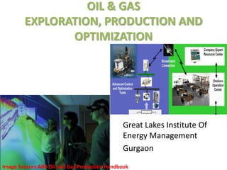
  • 1. OIL & GAS EXPLORATION, PRODUCTION AND OPTIMIZATION Great Lakes Institute Of Energy Management Gurgaon Image Sources:ABB Oil and Gas Production Handbook
  • 2. AGENDA • Geophysical data • Rigs, Drilling,Casing & Cementing • Wireline Logging • Completion of well(Well head, Christmas Tree) • Production, Well Testing • Decision Making • EOR • Case Study • Abandonment of a well
  • 3. GEOPHYSICAL DATA Riches in Rocks Image Sources:ABB Oil and Gas Production Handbook, Schlumberger Western Geco Public Site.
  • 4. RIGS • Land Rigs • Jack up Rigs • Drill Ships Image Sources:ABB Oil and Gas Production Handbook,Schlumberger Videos:From You Tube
  • 5. Different Types Of Rigs • Submersible This is a drilling structure which is used in relatively shallow water, usually 80 feet or less. It is towed to its location where it is submerged until it sits on the bottom. This submerging serves as its mooring system, although anchors may also be used. • Semi Submersible This rig has the hull design of a catamaran and is either towed or self- propelled. A semi-submersible can also be dynamically positioned or it can use anchors. When the rig is on location, it is ballasted down, in about the same way a submarine submerges, fifty feet or so to give it stability. Semis are heavy-duty rigs and are designed for adverse weather conditions. Image Sources:Google Images and Schlumberger.
  • 6. • Drill Ship A drillship can be one of two types: 1) It can be a ship which was designed and built to be a drilling vessel; or 2) A drillship can be an older vessel which has been refitted with drilling equipment. Drill ships are self-propelled, carrying a complete ship's crew while underway, as well as a crew of drilling personnel. Drill ships are moored either by the standard anchoring system or by dynamic positioning of the vessel. Dynamic positioning is the use of a computer-operated inboard thruster system which keeps the vessel on location without the use of anchors. This arrangement allows vessels to drill in ultra-deep water. • Jack up Jack-ups are towed to their location where rig personnel use heavy machinery to jack the legs down into the water until they are on the ocean floor. When this is competed, the platform containing the work area rises above the water. After the platform his risen about 50 feet out of the water, the rig is ready to begin drilling. Jack-up rigs are limited to a water depth of about 300 feet or less. Image Sources: Schlumberger and Google Images
  • 7. • Barge This is used to make extremely heavy lifts (The record to-date is 4,400 tons!) or to lay underwater pipelines. When these lifts are being made, there are usually a lot of support personnel on board (up to 200) including welders, electricians, riggers, operators, etc. Derrick barges can be either self-propelled or towed. Image Sources: Google Images
  • 8. PLATFORMS • Fixed Platform • Complaint Tower • Sea Star • Floating Production Systems • Tension Leg Platforms • Subsea Systems • Spar Platform Source: www.naturalgas.org
  • 9. FIXED PLATFORM Used In shallower water, if it is possible to physically attach a platform to the sea floor. How The 'legs' are constructed with concrete or steel, extending down from the platform, and fixed to the seafloor with piles. Weight of the legs and seafloor platform is substantial, so they do not have to be physically attached to the seafloor, but instead simply rest on their own mass. Many possible designs for these fixed, permanent platforms. Advantage The main advantages of these types of platforms are their stability, as they are attached to the sea floor there is limited exposure to movement due to wind and water forces. Limitation These platforms cannot be used in extremely deep water, not economical to build legs that long. Source: www.naturalgas.org
  • 10. COMPLAINT TOWER Much like fixed platforms. Each consists of a narrow tower, attached to a foundation on the seafloor and extending up to the platform Advantages The tower is flexible, as opposed to the relatively rigid legs of a fixed platform. This flexibility allows it to operate in much deeper water than fixed platforms Disadvantages The stability is far lesser than the fixed platforms. They get easily affected by rough weather and winds. Source: www.naturalgas.org
  • 11. SEASTAR PLATFORMS • Seastar Platforms are similar to tension leg platforms. • The platform consists of a floating rig, A lower hull is filled with water when drilling,. • Seastar platforms also incorporate the tension leg system employed in larger platforms. Tension legs are long, hollow tendons that extend from the seafloor to the floating platform. Advantages Seastar platforms are typically used for smaller deep-water reservoirs, when it is not economical to build a larger platform. They can operate in water depths of up to 3,500 feet. Source: www.naturalgas.org
  • 12. TENSION LEG PLATFORM Tension leg platform is similar to sea star platform. But unlike in sea star, the tension legs don't go all the way to the sea floor. The structure is held in a fixed position by tensioned tendons, which provide for use of the TLP in a broad water depth range up to about 2000m. The tendons are constructed as hollow high tensile strength steel pipes that carry the spare buoyancy of the structure and ensure limited vertical motion. Due to this the platform experiences more horizontal motion due to the jerks from the rough weather. This platform allows drilling at an amazing depth of 7000 feet. A variant is Seastar. Source: www.naturalgas.org
  • 13. SUBSEA SYSTEM • This platform has features from all the platforms that we discussed earlier. are wells located on the sea floor, as opposed to at the surface. Like in a floating production system, the petroleum is extracted at the seafloor, and then can be 'tied-back' to an already existing production platform or even an onshore facility . • It is used to drill at depths of 7000 and above. The drilling apparatus is fixed on the sea bed and the drilled oil is sent up with the help of risers. Source: www.naturalgas.org
  • 14. SPAR PLATFORM The SPAR consists of a single tall floating cylinder hull, supporting a fixed deck. The cylinder however does not extend all the way to the seafloor, but instead is tethered to the bottom by a series of cables and lines. SPAR is not an acronym, but refers to its likeness with a ship’s spar. Spars can support dry completion wells, but is more often used with subsea wells. Subsea production systems are wells located on the sea floor, as opposed to at the Source: www.naturalgas.org
  • 15. References • 8 References • Web on line sources and references that has been used in compiling this document: • · Schlumberger oilfield glossary: • http://www.glossary.oilfield.slb.com/default.cfm • · Norsk Hydro, Njord Main Process and Oil Process Description. • http://www.hydro.com/en/our_business/oil_energy/production/oil_gas_nor • way/njord.html • · Wikipedia http://en.wikipedia.org/wiki/Main_Page • · Oklahoma State, Marginal Well Commission, Pumper’s Manual • http://www.marginalwells.com/MWC/pumper_manual.htm • · Natural Gas Supply Association. See Natural Gas - From Wellhead to • Burner Tip • http://www.naturalgas.org/index.asp • · US geological survey: http://www.usgs.gov/ • · US department of energy: http://www.doe.gov/ • · NORSOK standards, Standards Norway (SN), • http://www.standard.no/imaker.exe?id=244 • · UK Offshore Operators Association (UKOOA) • http://www.oilandgas.org.uk/issues/storyofoil/index.htm • · National Biodiesel Board http://www.biodiesel.org/ • · PBS – Public Broadcasting Service - Extreme Oil • http://www.pbs.org/wnet/extremeoil/index.html • · http://www.priweb.org/ed/pgws/history/pennsylvania/pennsylvania.html
  • 16. COST COMPARISION FLOATING RIGS Rig Type Rigs Working Total Rig Fleet Average Day Rate Drillship < 4000’ WD 6 rigs 8 rigs $241000 Drillship 4000’ + WD 48 rigs 61 rigs $462000 Semisub < 1500’ WD 10 rigs 17 rigs $241000 Semisub 1500’ + WD 63 rigs 87 rigs $302000 Semisub 4000’ + WD 85 rigs 105 rigs $418000 Source: rigzone public site
  • 17. JACKUP RIGS Rig Type Rigs Working Total Rig Fleet Average Day Rate Jackup IC < 250’ WD 32 rigs 53 rigs $68000 Jackup IC 250’ WD 37 rigs 63 rigs $80000 Jackup IC 300’ WD 94 rigs 131 rigs $89000 Jackup IC 300’ + WD 122 rigs 151 rigs $144000 Jackup IS < 250’ WD 5 rigs 53 rigs $68000 Jackup IS 250’ WD 7 rigs 53 rigs $68000 Jackup IS 300’ WD 2 rigs 53 rigs $68000 Jackup IS 300’ + WD 1 rigs 53 rigs $68000 Jackup MC < 200’ WD 2 rigs 53 rigs $68000 Jackup MC 200’ + WD 12 rigs 28 rigs $46000 Jackup MS < 200’ WD 2 rigs 2 rigs - Jackup MS 200’ + WD 4 rigs 19 rigs $43000 Source: rigzone public site
  • 18. OTHER OFFSHORE RIGS Rig Type Rigs Working Total Rig Fleet Average Day Rate Drill Barge < 150’ WD 18 rigs 39 rigs - Drill Barge 150’ WD 6 rigs 9 rigs - Inland Barge 27 rigs 74 rigs $47000 Platform Rg 144 rigs 250 rigs $37000 Submersible 0 rigs 5 rigs - Tender 23 rigs 32 rigs $132000 Source: rigzone public site
  • 19. Classes of Oil well • Oil wells can generally be grouped into two categories: – Exploration or ‘Wild Cat’ • A potential ‘oil-field’ never drilled before – could be no oil – Development Oil field already present – simply extracting more oil
  • 20. DRILLING Horizontal Drilling It is an enhanced oil recovery (EOR) or gas recovery method . Casing Three different types Surface Intermediate Production Blow Out Preventer(BOP) Videos Source: You Tube Image Sources: Google Images
  • 21. BOP • Subsea Blow-out Preventor (BOP) stacks are specially designed to operate under water at great depths. • They are located on the sea bed, rather than above water on the rig. • Subsea BOPs are used only on floating rigs. • They are a very important safety device to prevent the well ‘blowing’ oil Source: ABB handbook
  • 22. WIRELINE LOGGING • Geological logs visual inspection of samples brought to the surface • Geophysical logs physical measurements made by instruments lowered into the hole . • Well logging is done during all phases of a well's development; drilling, completing, producing and abandoning. Image Source: Schlumberger Video Source: You Tube
  • 23. Cementing • Two processes – Wet and Dry • Sets through a chemical does not need air to set • Very complex chemistry Contains silica, alumina and iron oxide • Grind the resulting product to a fine powder Dry Cement Recipes A ‘recipe’ – a specific combination of chemicals mixed with neat cement and water to achieve a desired slurry/set cement. Many different additives in use • accelerators, retarders, dispersants, fluid-loss, extenders • Schlumberger uses ‘D’ codes to designate an additive Wet Source: Schlumberger
  • 24. Objectives of Cement Job • There are three main objectives: – Provide complete isolation of zones – Support the casing – Protect casing string Image Source: Schlumberger
  • 25. Completion Early wells were drilled in very shallow reservoirs which were sufficiently consolidated to prevent caving. As deeper wells were drilled, the problems associated with surface water prompted the use of a casing or conductor to isolate water and prevent caving of the wellbore walls. Further development of this process led to fully cased wellbores in which the interval of interest is perforated. Modern completions are now commonly undertaken in deep, hot and difficult conditions. In all cases, achieving the completion and eventual production objectives are a result of careful planning and preparation. Completion Types The most common criteria for the classification of completions include the following • Open-hole or cased hole, horizontal completion • Producing zones, i.e., single zone or multiple zone production • Production method, i.e., natural flowing or artificially induced production (Artificial Lift)
  • 26. • Open Hole Completion Barefoot completions are only feasible in reservoirs with sufficient formation strength to prevent caving or sloughing. In such completions there are no means of selectively producing or isolating intervals within the reservoir or open hole section. The production casing or liner is set and cemented in the reservoir cap rock, leaving the wellbore through to the reservoir open. The use of open hole completions is now restricted primarily to some types of horizontal wells and to wells where formation damage from (air drilling) drilling fluids is severe. To prevent an unstable formation from collapsing and plugging the wellbore, slotted screen or perforated liners may be placed across the open Source: Schlumberger
  • 27. • Cased Hole Completions Modern perforating charges and techniques are designed to provide a clear perforation tunnel through the damaged zone surrounding the wellbore. This provides access to the undamaged deformation, allowing the reservoir to be produced to its full capability. Cased and cemented wells generally require less complex pressure control procedures during the early stages of installing the completion components • Natural Flowing Wells completed in reservoirs which are capable of producing without assistance are typically more economic to produce. In general, naturally flowing wells require less complex downhole components and equipment. In addition, the long-term reliability and longevity of the downhole components is generally better than that of pumped completions. Source: Schlumberger
  • 28. • Artificial Completions All pumped, or artificially lifted, completions require the placement of specialized downhole components. Such components are electrically or mechanically operated, or are precision engineered devices. These features often mean the longevity or reliable working life of an artificial lift completion is limited. In addition, the maintenance or periodic workover requirements will generally be greater than that of a naturally flowing completion. • Artificial Lift Methods • Gas lift • Electric submersible pump • Plunger lift • Hydraulic or Jet Pump • Variable Cavity Pump (VCP) • Hydraulic or Jet pump • Progressive cavity pump (PCP)
  • 29. COMPLETION Completion Tubing Completion Assembly 1. Packer 2. Permanent Downhole Gauge 3. Safety Valve 4. Christmas Tree Video Source: You Tube Images Source: Google Images
  • 30. WELL TESTING Separator: To separate different constituents of drawn oil. Flaring: Burning the first few barrels. Source: ABB Handbook
  • 31. DECISION MAKING • Factors affecting the decision making in E&P. 1. Reservoir Technological factors, 2. Economic factors. Source: en.wikipedia.org
  • 32. RESERVOIR TECHNOLOGICAL FACTORS • Pressure, • Temperature, • Porosity, • Permeability, • API Gravity, • Sulphur Content. Source: en.wikipedia.org
  • 33. CRUDE OIL ANALYSIS Source: Oil and Gas Production Handbook by ABB
  • 34. PVT ANALYSIS Source: Oil and Gas Production Handbook by ABB
  • 35. POROSITY & SORTING Source: Oil and Gas Production Handbook by ABB
  • 36. POROSITY LEVEL IN RESERVOIRS POROSITY Percentage of Pores Usage Less than 10% Poor, Productivity Doubtful. 10 - 15% Fair. 15 - 25% Good, the most common range in production reservoirs. Over 25% Excellent, but rare. Source: Oil and Gas Production Handbook by ABB
  • 37. POROSITY Vs PERMEABILITY Source: Oil and Gas Production Handbook by ABB
  • 38. PERMEABILITY LEVEL IN RESERVOIRS Permeability Permeability Value Usage 10 mD Poor 100 mD Fair to Good 1000 mD Excellent, but rare. Source: Oil and Gas Production Handbook by ABB
  • 39. RELATIVE PERMEABILITY Source: Oil and Gas Production Handbook by ABB
  • 40. API GRAVITY Ideal value of API Gravity is 10 to 70. Source: Oil and Gas Production Handbook by ABB
  • 41. SULPHUR CONTENT Standard fuel oil - Sulphur content rate should not exceed 4.5% Low Sulphur fuel oil - Sulphur content rate should not exceed 1.5%. Sweet crude oil has a sulphur content less than 0.5%. Anything more than 0.5% is sour. Heavy crude is: • harder to handle (it is two thick to pump easily through pipelines unless diluted with light crude) • more expensive to refine to produce the most valuable petroleum products such as petrol, diesel and aviation fuel. • Sweet crude is preferable to sour because it is also (like light crude) more suited to the production of the most valuable refined products. Source: en.wikipedia.org
  • 42. ECONOMIC FACTORS • Cost of benefit. • Funds. • Rate of Return. Source: en.wikipedia.org
  • 43. Cost Benefit Analysis • Cost–benefit analysis (CBA) is a systematic process for calculating and comparing benefits and costs of a project for two purposes: • A) to determine if it is a sound investment to dig a well (justification/feasibility), • B) to see how it compares with alternate projects (ranking/priority assignment) • It involves comparing the total expected cost of each option against the total expected benefits, to see whether the benefits outweigh the costs, and by how much. Source: en.wikipedia.org
  • 44. FUNDS • NPV (net present value) • PVB (present value of benefits) • PVC (present value of costs) • BCR (benefit cost ratio) = PVB / PVC • Net benefit = (PVB - PVC) Source: en.wikipedia.org
  • 45. Rate of Return • Rate of Return indicate cash flow from an investment(Oil Well) to the investor over a specified period of time, usually a year. • ROR is a measure of investment profitability, not a measure of investment size. • The higher the investment risk, the greater the potential investment return, and the greater the potential investment loss. Source: en.wikipedia.org
  • 46. PRODUCTION OPTIMIZATION Improving Productivity is a huge problem. Various Factors : • Operational Costs • Hardware Damage • Reservoir Performance • Environmental Requirements • Operational Difficulties Source: Oil and Gas Production Handbook by ABB
  • 47. Applications included in Production Optimization • Flow line Control To stabilize the Multiphase Flow in gathering systems, risers & Flow lines. • Well Control To stabilize and Optimize gas lift and naturally flowing wells. • Slug Management It will help mitigate variations in Inflow impact. • Well Monitoring System Used to estimate the flow rates of Oil, Gas & Water from all the individual wells in an Oil Field. Source: Oil and Gas Production Handbook by ABB
  • 48. ENHANCED OIL RECOVERY AND IMPROVED OIL RECOVERY EOR:- •It is the process that seek to improve the recovery of hydrocarbon from a reservoir after the primary and secondary production phase. •Enhanced Oil Recovery is a generic term for techniques for increasing the amount of crude oil that can be extracted from an oil field. Using EOR, 30-60 %, or more, of the reservoir's original oil can be extracted compared with 20- 40% using primary and secondary recovery.
  • 49. Improved Oil Recovery:- • Any of various methods chiefly reservoir drive mechanism and enhanced recovery techniques, designed to improve the flow of hydrocarbons from the reservoir to the wellbore or to recover more oil after the primary and secondary methods(water- and gas floods). Primary Oil Recovery:- • This implies the initial production stage, resulted from the displacement energy naturally existing in a reservoir. Secondary Oil Recovery:- • A recovery improvement process such as water flooding and gas flooding.
  • 50.
  • 51.
  • 52. LIMITATIONS AND DISADVANTAGES OF PRIMARY AND SECONDARY RECOVERY PROCESSES • Rapid decrease in reservoir pressure – leads to low oil production rates and oil recovery (5 – 10 % of original oil in place). • Secondary recovery (water / gas injection) often does not yield a good recovery due to: - Reservoir heterogeneity -Unfavourable mobility ratio between oil and water - Water and gas coning problems - Low sweep efficiency
  • 53. WHEN TO START EOR? A common procedure for determining the optimum time to start EOR process after water flooding depends on:- • Anticipated oil recovery • Fluid production rates • Monetary investment • Costs of water treatment and pumping equipment • Costs of maintenance and operation of the water installation facilities. • Costs of drilling new injection wells or converting existing production wells into injectors.
  • 54. WHY EOR? Oil and Gas market ripe for breakthrough-EOR Solution:- • World oil consumption rate at 85 million barrel per day. • 1/3 production increases over next 15 years to meet projected demand. • Oil production faster, less expensive and with less disturbance to environment from existing wells. • EOR can prolong life of oil field upto 30 years . • There is significant oil in place in discovered reservoirs that will otherwise not be recovered. • EOR can make an important contribution to world oil supply in the long term. • EOR economics can be attractive.
  • 55. WORLD OIL PRODUCTION FORECAST (IEA)
  • 56. • 64 million b/d of capacity additions needed by 2030. • 5 million b/d is forecast to be supplied by EOR in 2030. • 20 million b/d is from fields yet to be found. • 33% recovery efficiency ->EOR target of 2.2 trillion barrels in discovered fields.
  • 57. A Boom of EOR Program:- • Proven reserves • Hard to get oil • Demand outstripping supply • Cost of finding new oil reservoir • Political problems • Environmental concern Example-Occidental Chemical Co. maintains a very successful EOR program, producing approximately 350000 barrels of oil equivalent per day.
  • 58. Business Benefits:- • Optimize oil recovery with field proven flow and density solutions • Simplify operations and reduce maintenance costs with reliable and accurate measurement • Multi-variable output and process intelligence enable remote surveillance and reduced operator intervention • Reduce chemical costs through accurate flood material allocation and dosage
  • 59. EOR POTENTIAL Opportunities:- • Target resource for EOR applications is 6 trillion barrels, of the 9 trillion initially in place. • Widespread application could far exceed the current forecasts. • Chemical / polymer flooding has large unrealized potential. • Both hydrocarbon and CO2 miscible flooding have large potential internationally. • A significant resource exists in the offshore, as well as onshore . • CO2 sequestration may provide an additional impetus and opportunity.
  • 60. WHY EOR IS NEEDED NOW? • Design and implementation of an EOR project takes time. • After implementation (especially as a tertiary project) production response does not occur immediately. EOR Project Time Line
  • 61. EOR TECHNIQUES 1. Gas Injection • Carbon Dioxide Flooding • Miscible Solvent(LPG or Propane) • Enriched Gas Drive • High-Pressure Gas drive • Inert Gas( Nitrogen) • Flue Gas
  • 62. Carbon Dioxide Flooding • Commonly used approach. • Aids recovery by reducing the viscosity of the crude oil as the gas mixes with it. • Air cannot be used to repressurize the reservoir because the oil will quickly catch on fire. • Oil displacement by carbon dioxide injection relies on the phase behaviour of the mixtures of that gas and the crude, which are strongly dependent on reservoir temperature, pressure and crude oil composition.
  • 63.
  • 64. Benefits of CO2 Flooding:- • Injections of CO2 work with lighter gravities. • Its production has been growing steadily, and volumes reached 240,000 barrels a day in 2008, a tenfold increase from 28,000 barrels a day in 1986. • WAG is frequently used in carbon dioxide flooding to increase sweep efficiency and decrease the need for expensive solvents.
  • 65. Cost of CO2 Flooding:- • Adding oil recovery methods adds to the cost of oil — in the case of CO2 typically between 0.5-8.0 US$ per tonne of CO2. • Onshore EOR has paid in the range of a net 10-16 US$ per tonne of CO2 injected for oil prices of 15-20 US$/barrel. • With oil prices at around 90 US$/barrel, the economic benefit is about 70 US$ per tonne CO2.
  • 66. Benefits of Inert gas flooding:- • Availability and low cost. • Prevention of oil encroachment into the gas cap when gas cap is present. • Higher recoveries compared to water drive in reservoirs having low permeability. • Residual inert gas at abandonment rather than saleable natural gas. • Reliability of the supply.
  • 67. 2. Chemical Flooding • Alkaline Surfactant Polymer or Caustic flooding • Polymer-augmented water flooding • Surfactant flooding -Low tension water flooding -Micellar/Polymer(micro emulsion) flooding
  • 68. Alkaline Surfactant Polymer Flooding • ASP flooding is a form of chemical enhanced oil recovery (EOR) that can allow operators to extend reservoir pool life and extract incremental reserves currently inaccessible by conventional EOR techniques such as water flooding. • Injection of diluted alkaline or caustic solutions into oil reservoir to improve oil recovery. • In the polymer flooding method, water-soluble polymers increase the viscosity of the injected water, leading to a more efficient displacement of moderately viscous oils. • Although no large-scale surfactant-polymer floods have been implemented, the process has considerable potential to recover oil. • For all chemical flooding processes, inclusion of a viscosifier (usually a water-soluble polymer) is required to provide an efficient sweep of the expensive chemicals through the reservoir.
  • 69. Benefits of ASP Flooding:- • It is used for oils that are more viscous than those oils recovered by gas injection methods. • Presently have the highest application potential, since they are low risk methods with a well developed application technology. • Surfactant/polymer flooding is an immature method from an application point of view. It will need substantial research and development to become a technique of any importance compared to ASP.
  • 70. • The potential and feasibility of ASP flooding continues to grow and offers much potential for increased oil recovery. • Achievement of 20% incremental oil recovery. Example-Husky Taber South Mannville B Pool began ASP flooding in 2006 and is currently ongoing. Cost Factor:- Application of these methods is usually limited by the cost of the chemicals and their adsorption and loss onto the rock of the oil containing formation.
  • 71. Developments in Chemical Flooding • Advances in surfactants:- –Thermally stable surfactants (e.g. sulphonates) remove temperature restrictions. –Surfactants designed to be active at 0.1% concentrations. –Sacrificial agents (e.g., sodium carbonate) reduce adsorption to very low levels. • Alkaline flooding:- –Alkaline-polymer (AP) and alkaline-surfactant-polymer (ASP) are new, lower-cost EOR methods.
  • 72. 3. Thermal Recovery • Steam flooding or Steam-drive • Cyclic Steam Injection • In-situ combustion • Thermally assisted gas-oil gravity drainage (TAGOGD)
  • 73. Steam Flooding • It is used to heat the crude oil in the formation to reduce its viscosity and/or vaporize part of the oil. • It improves the sweep efficiency and the displacement efficiency. • Steam injection has been used commercially since the 1960s in California fields. • In 2011, Solar Thermal Enhanced Oil Recovery projects were started in California and Oman, this method is similar to Thermal EOR but uses a solar array to produce the steam.
  • 74.
  • 75. Benefits of Steam Flooding:- • It has the greatest certainty of success and potential application is about 70% of EOR worldwide. • Provides highest recoveries at the lowest cost. • Can be used for heavy oil with a viscosity less than 10,000 centipoises. • Power track record to produce 15-20% of the original oil in place.
  • 76. Developments in Thermal Recovery • Controlled Combustion:- – Removes depth, pressure restrictions of steam – Applicable to light oils • Steam-Assisted Gravity Drainage (SAGD):- – Uses horizontal wells to contact formation, reduce well costs – Modification of steam drive
  • 77.
  • 78. 4. Microbial Injection • Its’ aim is to improve the recovery of oil entrapped in porous media while increasing economic profits. • MEOR is a tertiary oil extraction technology allowing the partial recovery of the commonly residual two-thirds of oil, thus increasing the life of mature oil reservoirs. • Rarely used, both because of its higher cost and because the developments in this field are more recent than other techniques. • This approach has been used in oilfields near the Four Corners and in the Beverly Hills Oil Field in Beverly Hills, California.
  • 79. Limitations of MEOR:- 1) Increasing salinity absorbs water from the microbe and negatively affects its growth. 2) Permeability, temperature, pressure, salinity and pH affect the selection of microbes. 3) Study of bacteria metabolism, and relation to subsurface environment, need great effort. 4) Microbes Produce H2S and SO2 causing bio-corrosion of the equipment, and contamination of ground water. But on the other hand microbes produce organic chemicals less harmful than synthetic chemicals used by EOR methods. Economics of MEOR:- • Microbes and nutrients are relatively cheap materials. • Cost is independent of oil prices. • Implementation needs minor modifications to field facilities. • Economically attractive for marginal producing wells. • The total cost of incremental oil production from MEOR is only 2 – 3 $/bbl.
  • 80. EOR Oil Production (Source: OGJ EOR Survey, 2010) Worldwide EOR Oil Production US EOR Oil Production
  • 81. • U.S. EOR production is ~12% of the U.S. total Two major contributors: Thermal recovery using steam injection and Carbon dioxide miscible recovery. • Thermal recovery in Venezuela, Indonesia, China, Canada. • Gas injection in Canada, Venezuela, and Libya. • Chemical/polymer applications in China. (Source: OGJ biennial surveys)
  • 82. Screening criteria for EOR Methods
  • 83. EOR Methods Based on Lithology Source: SPE 130113, Manrique E., et al; April 201
  • 84. DENSITY RANGE FOR EOR METHODS
  • 85. COST COMPARISON FOR VARIOUS EOR METHODS
  • 86. ECONOMICS CHALLENGES • Thermal:- – High cost – Greenhouse gas emissions – Combustion - perceived high risk • Chemical – Polymer:- – Long lead times, long payout – Perceived high risk • CO2 Miscible:- – Access to CO2 However, Long term demand and price increases present opportunities
  • 87. POLITICAL ISSUES • NOC, IOC, Governmental Relationships can harm EOR opportunities:- –Mutual interests are hampered by short-term considerations. – Access may be lost by P&A regulations. – Economics hampered by loss of tax incentives. • Solution: treat EOR differently – Jointly share technical, economic risk. – Maintain access to wells and facilities that can be used for EOR (don’t require premature PA). – Revise concession terms to include life-of-project for EOR.
  • 88. Case Study • The Handil Oil Field Handil is a giant oil field in the Mahakam Province of Indonesia, discovered in 1974 and still operated by 'TOTAL Exploration and Production Indonesia'. http://www.theoildrum.com/node/4307
  • 90. Results In November 1995 a lean gas injection project was initiated in five reservoirs. The project boosted the production of the five large reservoirs and altered the overall decline rate of the field.
  • 91. THANK YOU

Editor's Notes

  1. Source:Wikipedia
  2. Soucre:13th European Symposium on Improved Oil Recovery– Budapest, Hungary, 25-27 April 2005
  3. Source: Department of Petroleum Engineering Norwegian University of Science &amp; Technology, Trondheim, Norway
  4. Source: Department of Petroleum Engineering Norwegian University of Science &amp; Technology, Trondheim, Norway
  5. Source: NTNU, autumn 2009.
  6. Source: en.wikipedia.org
  7. Source: OGJ Survey
  8. Source: OGJ Survey
  9. Source: NTNU, autumn 2009.
  10. Source: NTNU, autumn 2009.
  11. Source: NTNU, autumn 2009.
  12. Source: OGJ Survey
  13. Source: Technology Strategy for Enhanced Recovery; OG21
  14. Source: Technology Strategy for Enhanced Recovery; OG21
  15. Source: Google Images
  16. Source: en.wikipedia.org
  17. Source: en.wikipedia.org
  18. Source: Department of Petroleum Engineering Norwegian University of Science &amp; Technology, Trondheim, Norway
  19. Source: Technology Strategy for Enhanced Recovery; OG21
  20. Source: en.wikipedia.org
  21. Source: Technology Strategy for Enhanced Recovery; OG21
  22. Source: en.wikipedia.org
  23. Source: OGJ Survey
  24. Source: www.cseg.ca
  25. Source: en.wikipedia.org
  26. Source: Google Images
  27. Sources: en.wikipedia.org
  28. Source: OGJ Survey
  29. Source: Google Images
  30. Source: en.wikipedia.org
  31. Source: Department of Petroleum Engineering Norwegian University of Science &amp; Technology, Trondheim, Norway
  32. Source: Department of Petroleum Engineering Norwegian University of Science &amp; Technology, Trondheim, Norway
  33. Source: Department of Petroleum Engineering Norwegian University of Science &amp; Technology, Trondheim, Norway
  34. Source: Department of Petroleum Engineering Norwegian University of Science &amp; Technology, Trondheim, Norway
  35. Source: OGJ Survey
  36. Source: OGJ Survey