
Recommended
More Related Content
What's hot
What's hot (20)
Viewers also liked
Viewers also liked (20)
Similar to Reservoir evaluation method 101
Similar to Reservoir evaluation method 101 (20)
Recently uploaded
Recently uploaded (20)
Reservoir evaluation method 101
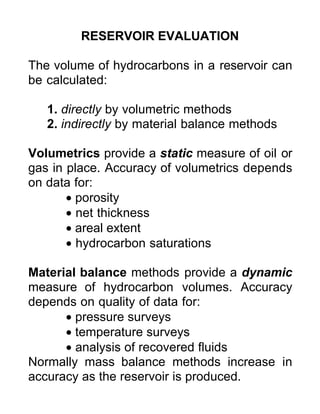
- 1. RESERVOIR EVALUATION The volume of hydrocarbons in a reservoir can be calculated: 1. directly by volumetric methods 2. indirectly by material balance methods Volumetrics provide a static measure of oil or gas in place. Accuracy of volumetrics depends on data for: • porosity • net thickness • areal extent • hydrocarbon saturations Material balance methods provide a dynamic measure of hydrocarbon volumes. Accuracy depends on quality of data for: • pressure surveys • temperature surveys • analysis of recovered fluids Normally mass balance methods increase in accuracy as the reservoir is produced.
- 2. VOLUMETRIC ANALYSIS Also known as the geologist's method because it is based on geological maps, core logs and analysis of wireline logs. Isopach maps are used to compute the bulk volume of the reservoir (V). For an oil reservoir above the bubble point the oil-originally-in-place (OOIP) is given by: OOIP = (V.n).(1 - Swi) The stock tank oil in place is given by: STOIP = (V.n).(1 - Swi) / Bo where Bo is the oil formation volume factor. The volume x porosity is the pore volume for the reservoir (PV). So the OIP is also known as the hydrocarbon pore volume (HCPV): HCPV = (V.n).(1 - Swi) = PV.(1 - Swi) The moveable oil volume (MOV) is given by: MOV = PV.(1 - Swi - Soi)
- 3. GAS VOLUMES The volume of free gas in a gas reservoir or gas- initially-in-place is given by: GIIP = Gr = (V.n).(1 - Swi) In terms of standard volumes at STP, the gas volume is: G = (V.n).(1 - Swi) / Bg G = (V.n).(1 - Swi).E where Bg is the gas formation volume factor and E is the gas expansion factor. For oil and gas reservoirs below the bubble point, the total hydrocarbon in place is given by the HCPV: HCPV = (V.n).(1 - Swi) The stock tank oil volume can be computed as: STOIP = (V.n).(1 - Swi - Sg) / Bo The standard gas volume at STP is given by: G = (V.n).(1 - Swi - So) / Bg
- 4. VOLUME CALCULATIONS To calculate volumes it is necessary to find the areas between isopach contours. There are several methods: 1. grid square counting 2. planimeter 3. digitizer table Given the areas between contours, volumes can be computed using: 1. Trapezoidal rule 2. Simpson's rule For the trapezoidal rule with a contour interval, h, and where hn is z-distance from the top contour to the crest of the reservoir : V = h.[Ao + 2A1 + 2A2 + ...+ 2An-1 + An] + hn.An 2 2 Using Simpson's rule with a contour interval, h, and an even number of intervals (odd number of lines) : V = h.[Ao + 4A1 + 2A2+ ... + 2An-2 + 4An-1 + An] + hn.An 2 2 AoA3 A2 A1
- 5. USE OF VOLUMETRICS In order to calculate stock tank volumes the formation volume factors Bo and Bg are required. Both Bo and Bg are functions of pressure (and consequently of reservoir depth). There are various methods of calculating an averaging pressure over a reservoir: 1. well pressure over n wells pav = Σpi / Σi 2. areal pressure over n sub-areas pav = Σpi.Ai / ΣAi 3. volumetric pressure over n sub-volumes pav = Σpi.Ai.zi / ΣAi.zi The volumetric average gives the best estimate. Formation volume factors can also be averaged in the same way: [Bo]av = ΣBo(pi).Ai.zi / ΣAi.zi [Bg]av = ΣBg(pi).Ai.zi / ΣAi.zi
- 6. NET PAY CUT-OFFS Net pay cut-offs are assigned on the basis of : 1. effective porosity (e.g. > 8%) 2. permeability (e.g. > 1 md) 3. thickness (e.g. > 1 m) Wireline logs can also be used to assign net pay. SP, porosity and density logs are used in this way. Combinations of n, k, and z may be used to provide a cut-off for a particular reservoir, field or pool. Gross pay is the entire reservoir, net pay involves some kind of cut-off decision. Volumetric estimates of OOIP and GIIP may be based on gross pay or net pay. Net pay volumes are used almost exclusively in economic analyses.
- 7. DRIVE MECHANISMS Material balance methods involve estimation of reservoir recovery from the PVT behaviour of the reservoir and contained fluids. Fluid phase expansion and rock skeleton compression and can combine in a number of ways to provide the energy to drive hydrocarbons from subsurface reservoirs: • Solution Gas Drive (or Depletion Drive) • Gas Cap Drive (and Gravity Drainage) • Natural Water Drive • Compaction Drive • Combination Drive Ultimate oil and gas recoveries vary depending on the drive mechanism. For oil, water drive is most effective. Typical primary recoveries are in the 25-40% range (maximum 75%). For gas, gravity drainage, water drive and depletion drive can provide > 80% recovery.
- 8. SOLUTION GAS DRIVE The principle of solution gas drive or depletion drive is the expansion of dissolved gas and liquid oil in response to a pressure drop. The change in fluid volume results in production. Above the bubble point, only liquid oil expansion occurs. Below the bubble point, both liquid oil expansion and gas expansion contribute to volume change. Dissolved gas reservoirs typically recover between 5 and 25% OOIP and 60 to 80% GIIP. The Upper Cretaceous Cardium sand reservoir is an example of a depletion drive reservoir.
- 9. SOLUTION GAS DRIVE HISTORY • rapid and continuous pressure drop, rate of decline falls at bubble point pressure. • Rs (solution gas oil ratio) low until p = pb, then increases to maximum and declines. • absent or minimal water influx (watercut). • gravity drainage is a special case in steeply dipping reservoirs where gas drives out more oil. • maintaining pressure above bubble point produces oil rather than gas for p < pb. • well production declines rapidly, early pumping required. watercut GOR (R) pressure time Rsi
- 10. GAS CAP DRIVE The principle of gas cap drive or depletion is the expansion of free gas and in response to a pressure drop. The change in fluid volume results in production. Gas cap expansion maintains the pressure in the oil leg. Gas cap drive reservoirs typically recover 20 to 40% OOIP, sometimes as high as 60%. The Lower Mississippian Turner Valley carbonate was a gas cap drive reservoir.
- 11. GAS CAP DRIVE HISTORY • pressure drops continuously, but slowly. • Rs (solution gas oil ratio) increases continuously. • water influx (watercut) absent or minimal • gas cap cannot be allowed to shrink or oil encroachment will occur resulting in reduced recovery. • oil leg wells can eventually produce gas. • Wells have long flowing life (depending on the size of the gas cap). watercut GOR (R) pressure time Rsi
- 12. NATURAL WATER DRIVE (1) The principle of natural water drive is that an aquifer provides the energy for hydrocarbon production. Both water expansion as a result of pressure reduction and inflow are involved. Natural water drive is associated with high recovery rates, oil from 35-75% OOIP, gas from 60-80% GIIP. Bottom water drive, where the water leg underlies the entire reservoir, and edge water drive, where only part of the areal extent is contacted by water, are recognized. The Upper Devonian Leduc pools are driven by inflow from the Cooking Lake Aquifer. BOTTOM WATEREDGE WATER
- 13. NATURAL WATER DRIVE (2) It is not uncommon for flow from the surface to supply the energy for natural water drive. When a pressure drop occurs, both the oil and water liquid phases expand resulting in production. Additionally, water inflow radially and vertically displaces the oil towards the producers.
- 14. NATURAL WATER DRIVE HISTORY • pressure remains high, small drop. • Rs (solution gas oil ratio) remains low. • water influx starts early and increases to appreciable levels. • Residual oil may be trapped behind the advancing water. • Wells flow freely until water production (watercut) becomes excessive. watercut GOR (R) pressure time Rsi
- 15. COMPACTION DRIVE In compaction drive, the energy for oil production is provided by the collapse of the porous medium skeleton and expansion of the pore fluids when the reservoir pressure drops. The increase in the "grain pressure" or effective stress causes pore collapse and compaction (consolidation) of the reservoir. This drive mechanism is common in highly compressible, unconsolidated reservoirs such as those found in California, Venezuela, and the heavy oil deposits of western Canada. The Lower Cretaceous (Mannville) Clearwater sands in the Cold Lake district provide an example of compaction drive.
- 16. COMBINATION DRIVE In combination drive reservoirs, at least two of the basic drive mechanisms are active in expelling oil: • solution gas exsolution • gas cap expansion • natural water influx • pore collapse The example shows a combination of natural water influx and gas cap drive. In many of the western Canadian heavy oil deposits, solution gas drive and compaction drive act in combination, for example the Lower Cretaceous (Mannville) Waseca sand in the Lloydminster district.
- 17. RESERVOIR PERFORMANCE DATA Pressure trends in reservoirs under various drive mechanisms are distinctive. Producing GOR is also strongly diagnostic of drive mechanism. 100 80 60 40 20 0 0 10 20 30 40 50 %OOIP Produced P % WATER DRIVE GAS CAP DRIVE SOLUTION GAS DRIVE 100 80 60 40 20 0 0 10 20 30 40 50 %OOIP Produced GOR % SOLUTION GAS DRIVE GAS CAP DRIVE WATER DRIVE