The document discusses various techniques for encoding analog signals into digital pulses for transmission, including:
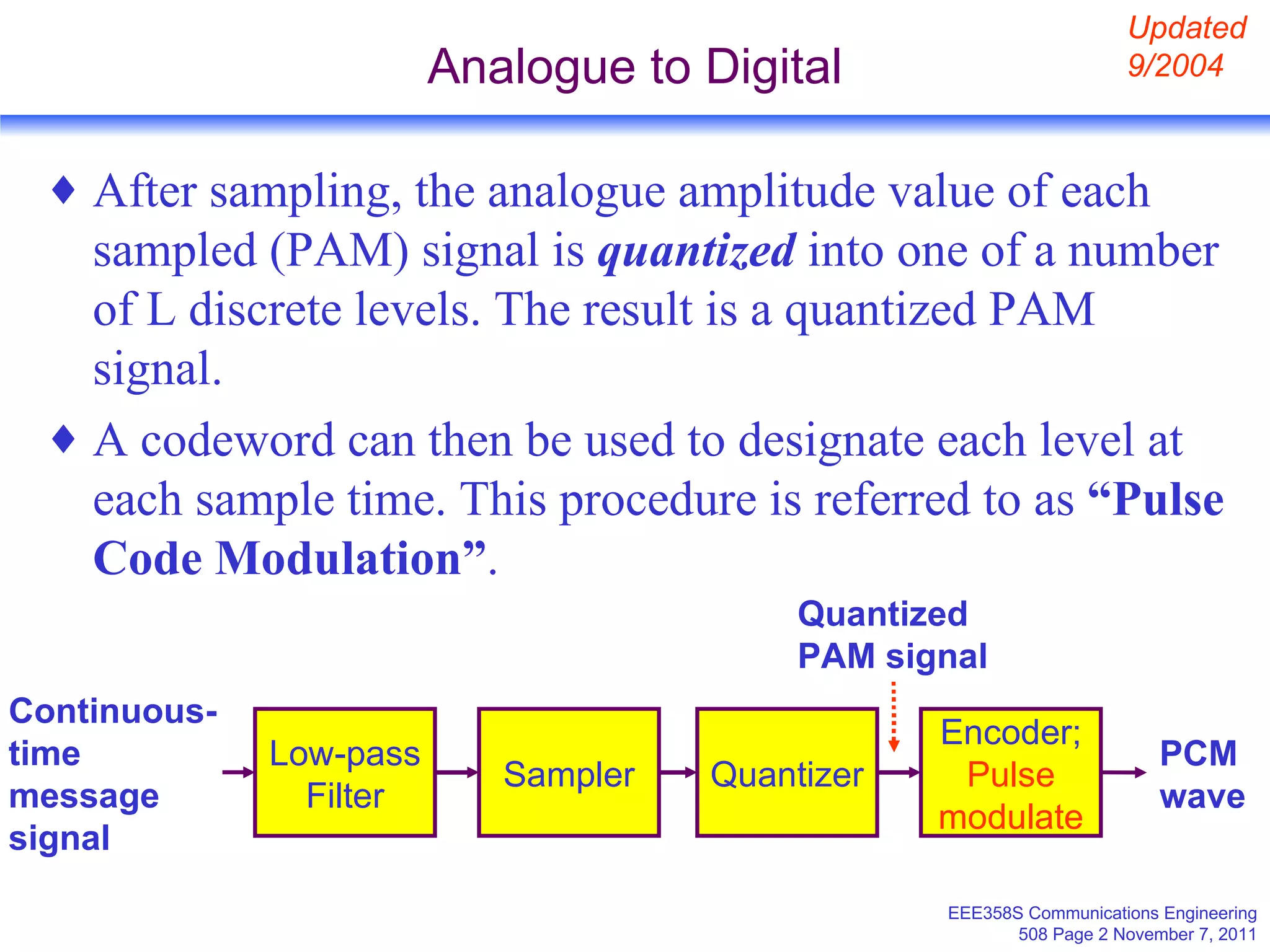
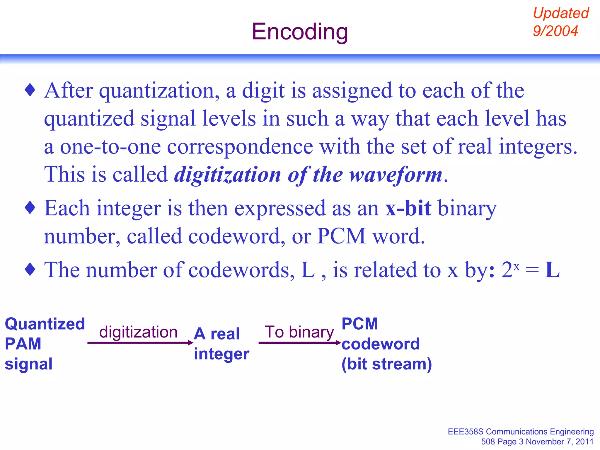
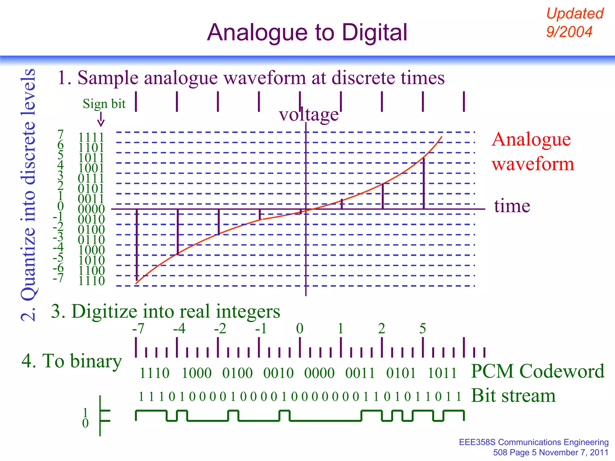
1. Pulse code modulation (PCM) which samples and quantizes an analog signal then assigns a codeword to each quantization level.
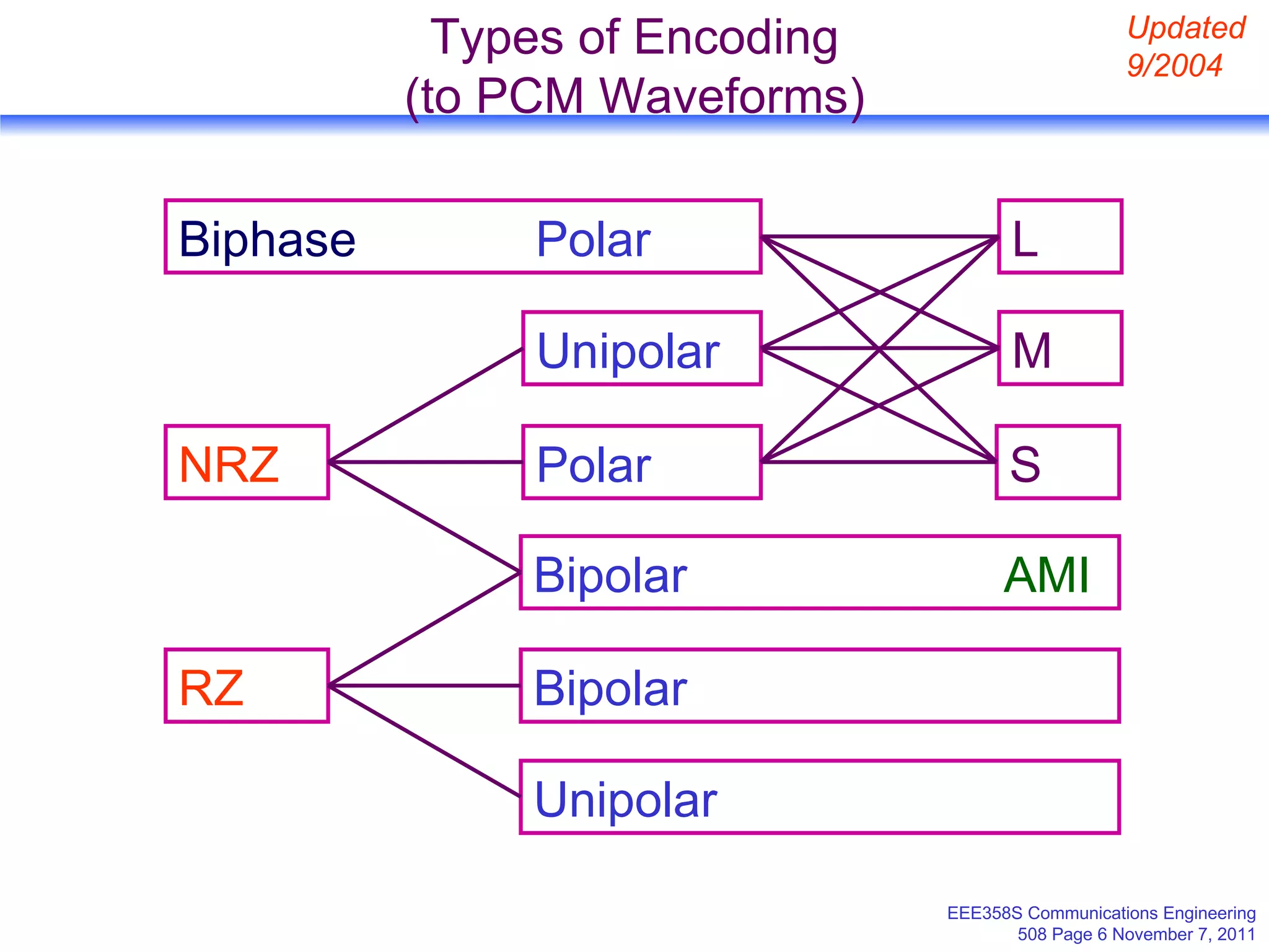
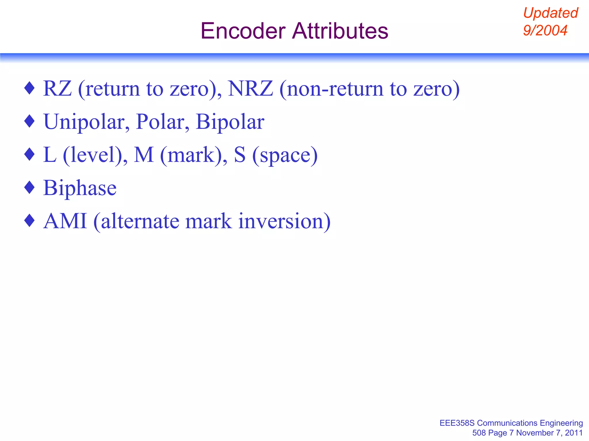
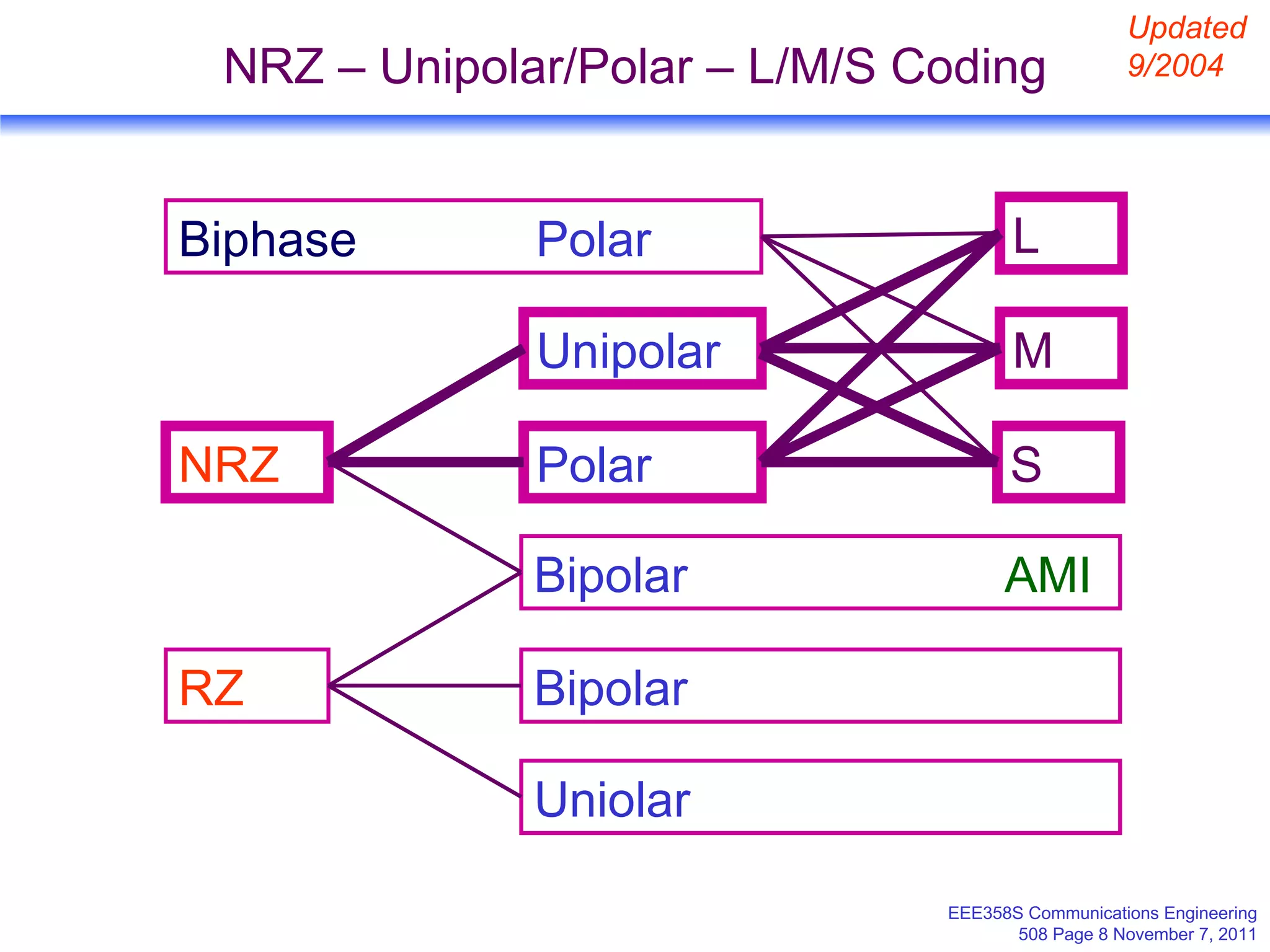
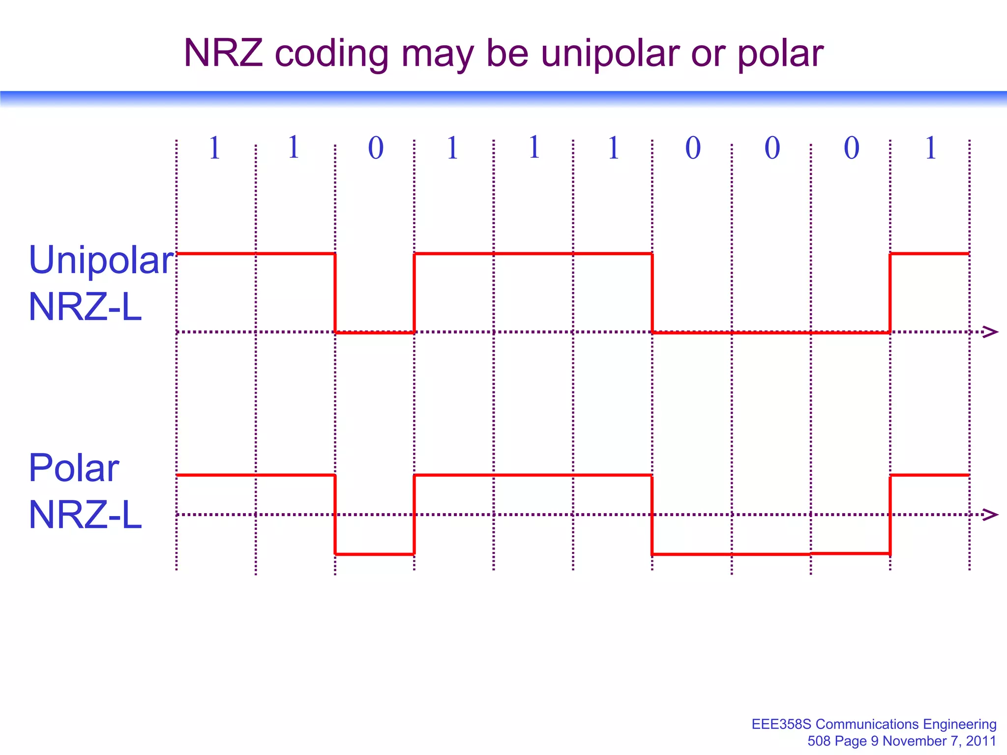
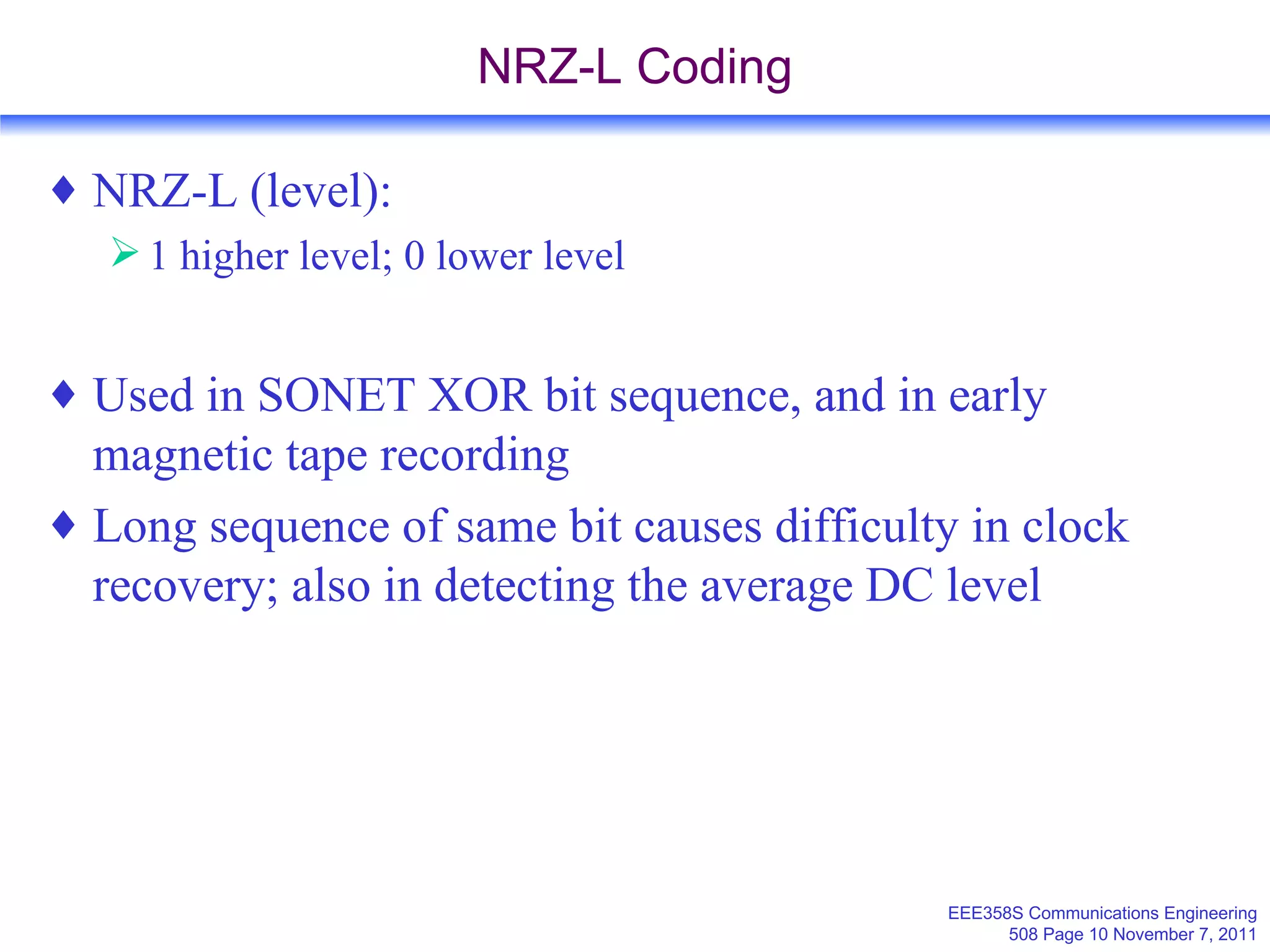
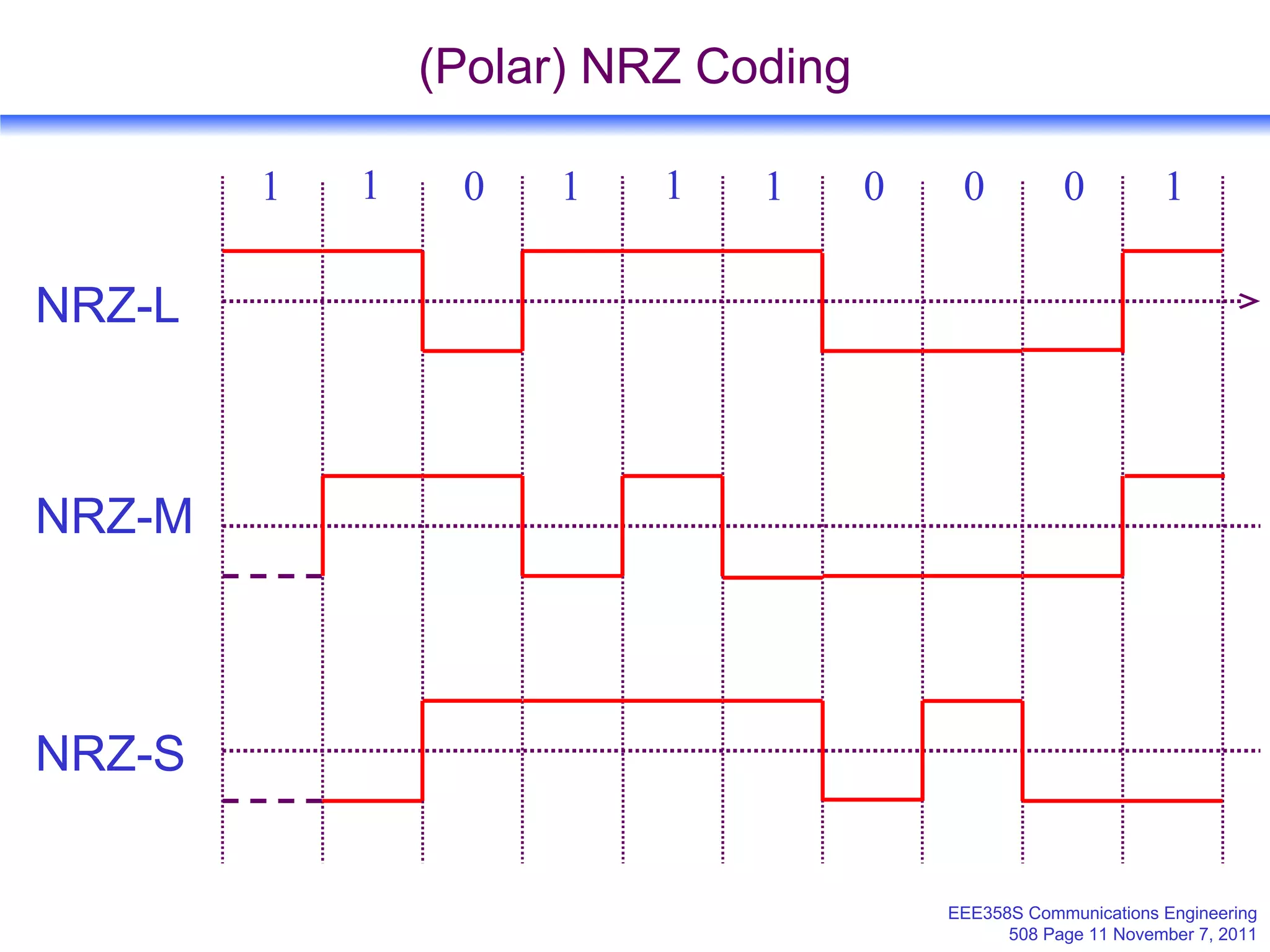
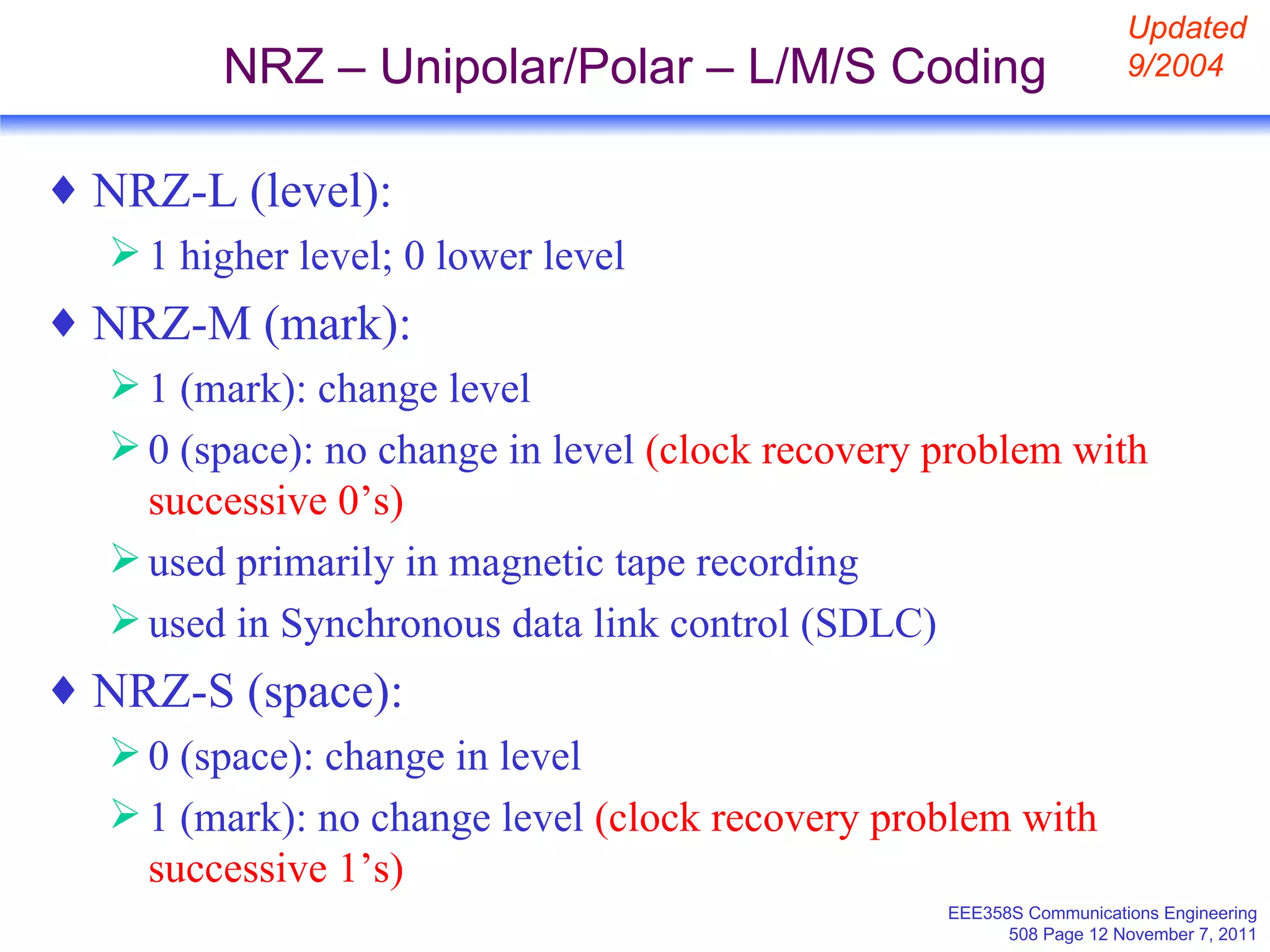
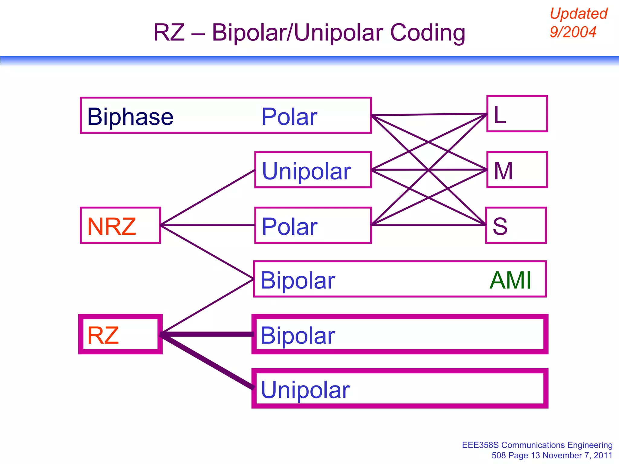
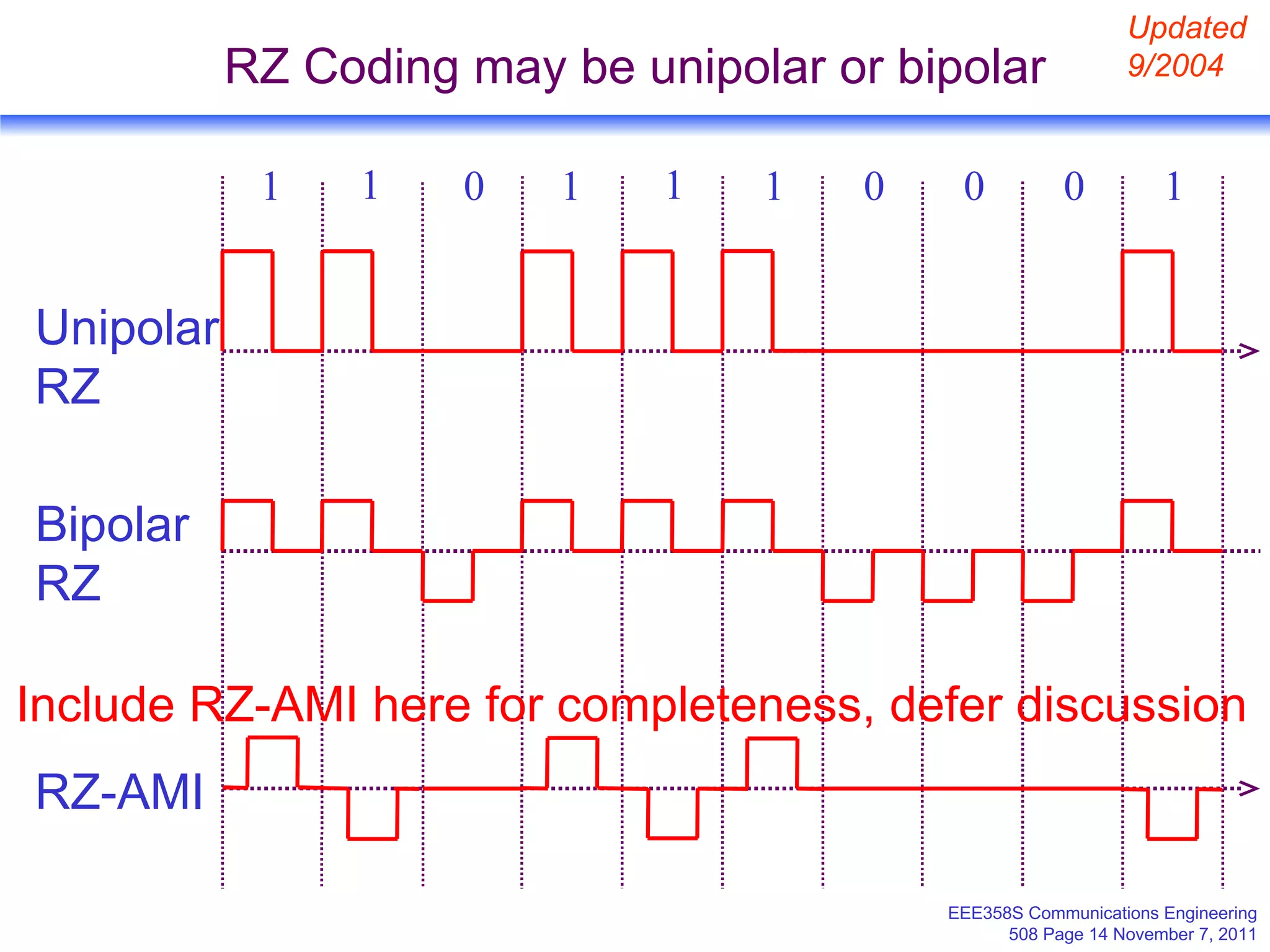
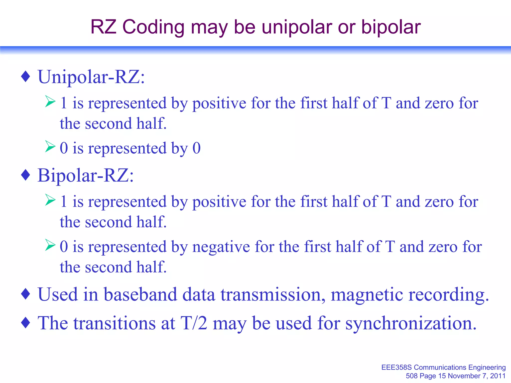
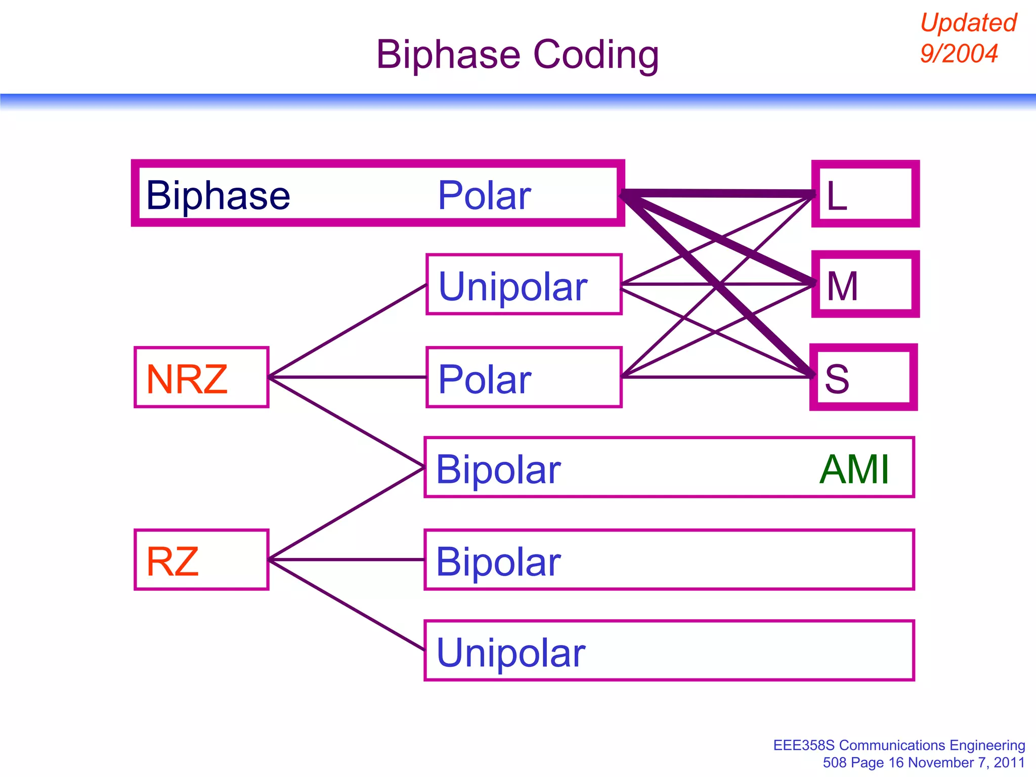
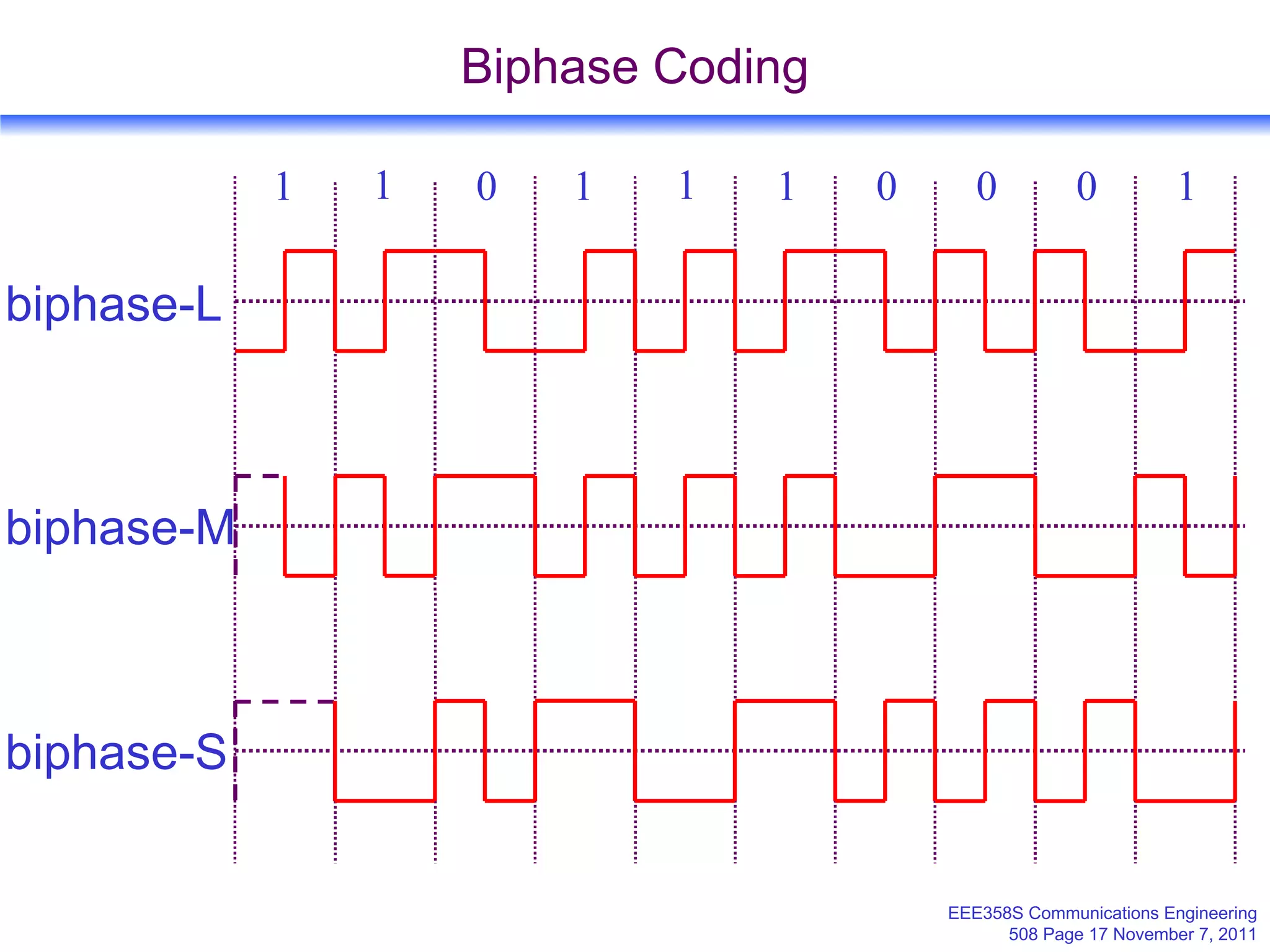
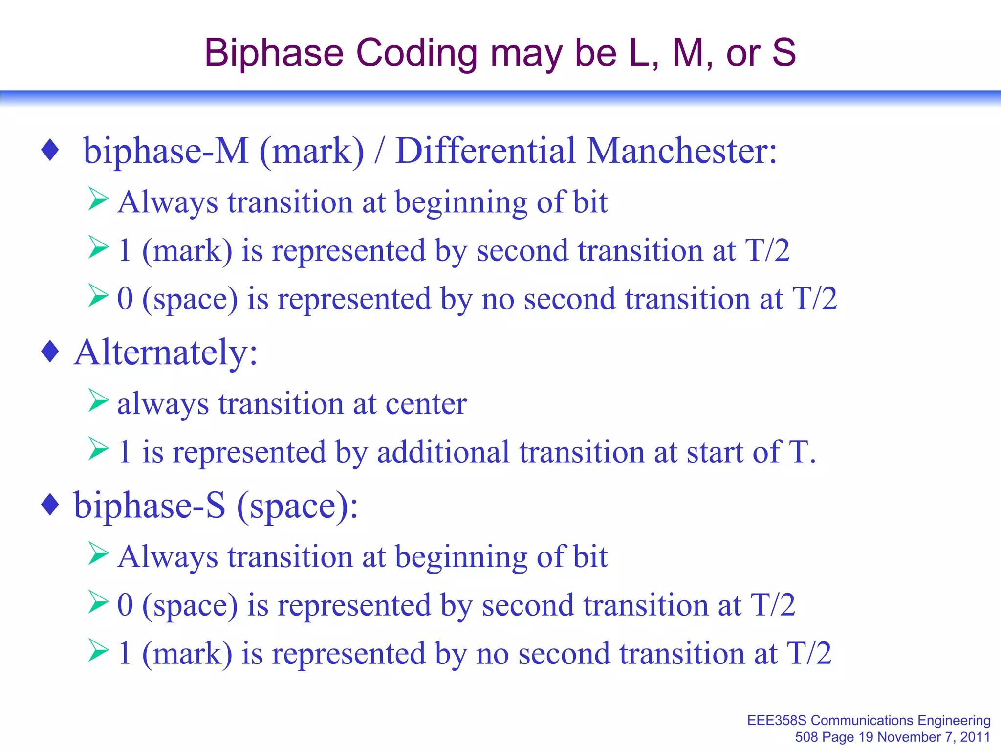
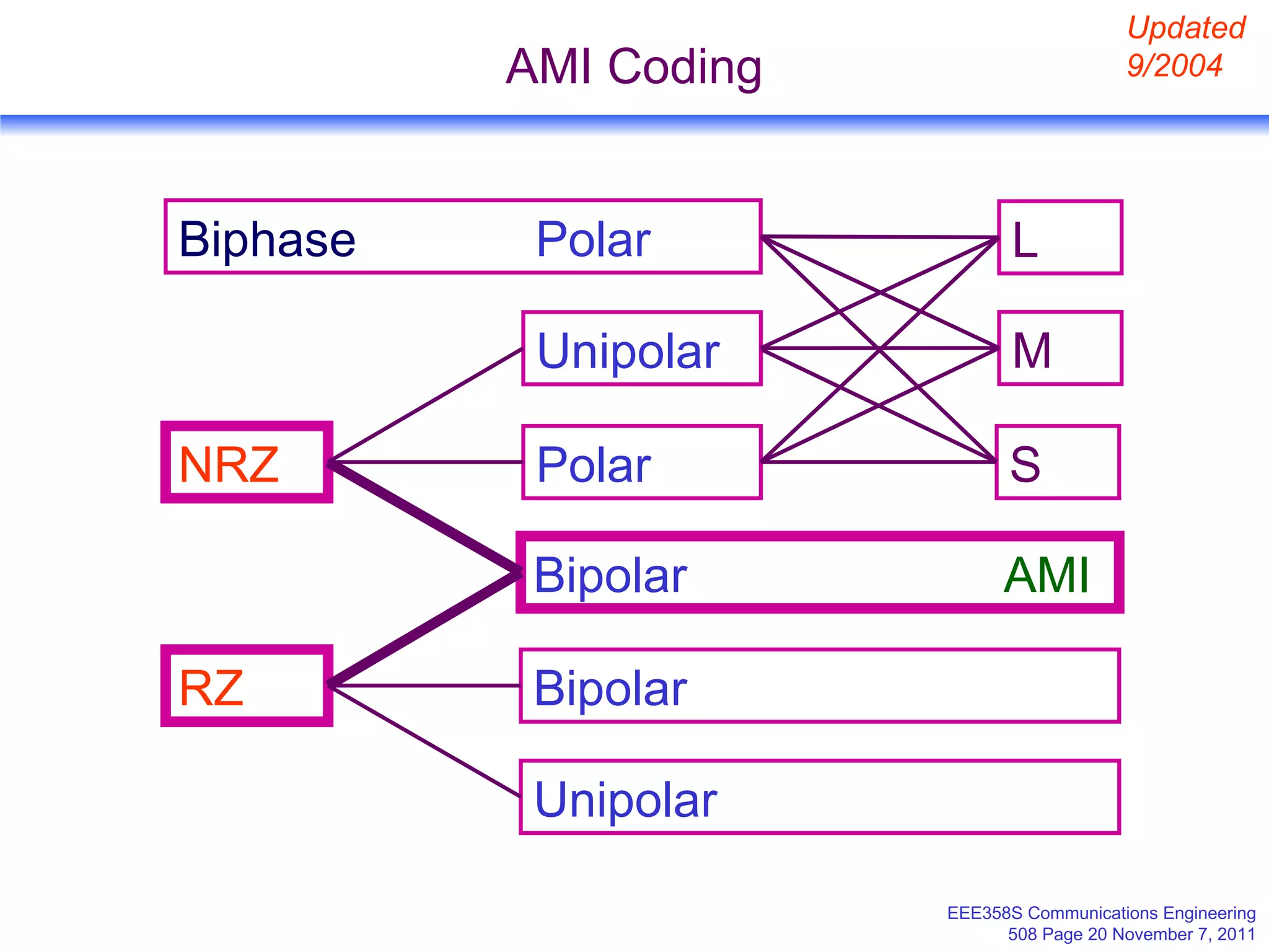
2. Common encoding schemes for the digital pulses including unipolar, polar, and bipolar encodings as well as return-to-zero (RZ) and non-return-to-zero (NRZ).
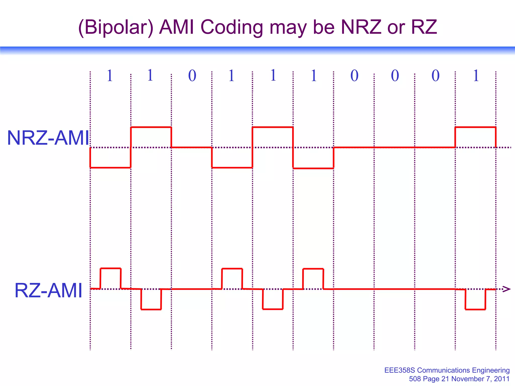
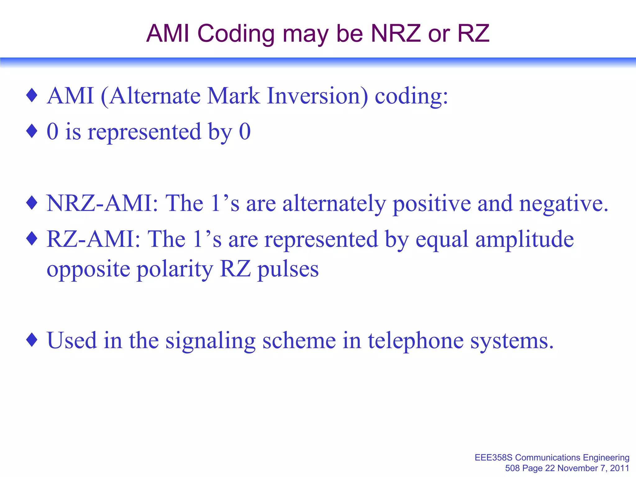
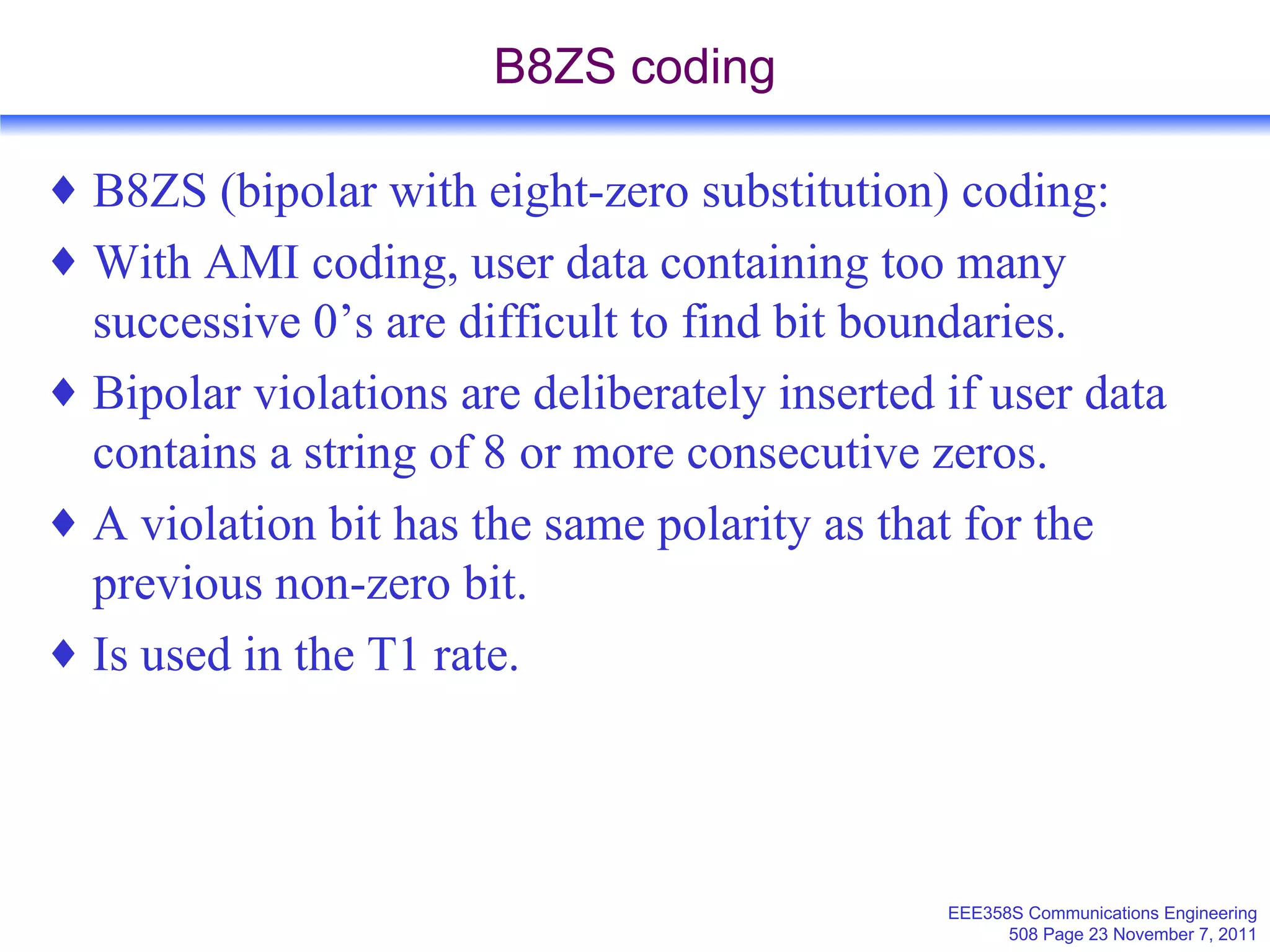
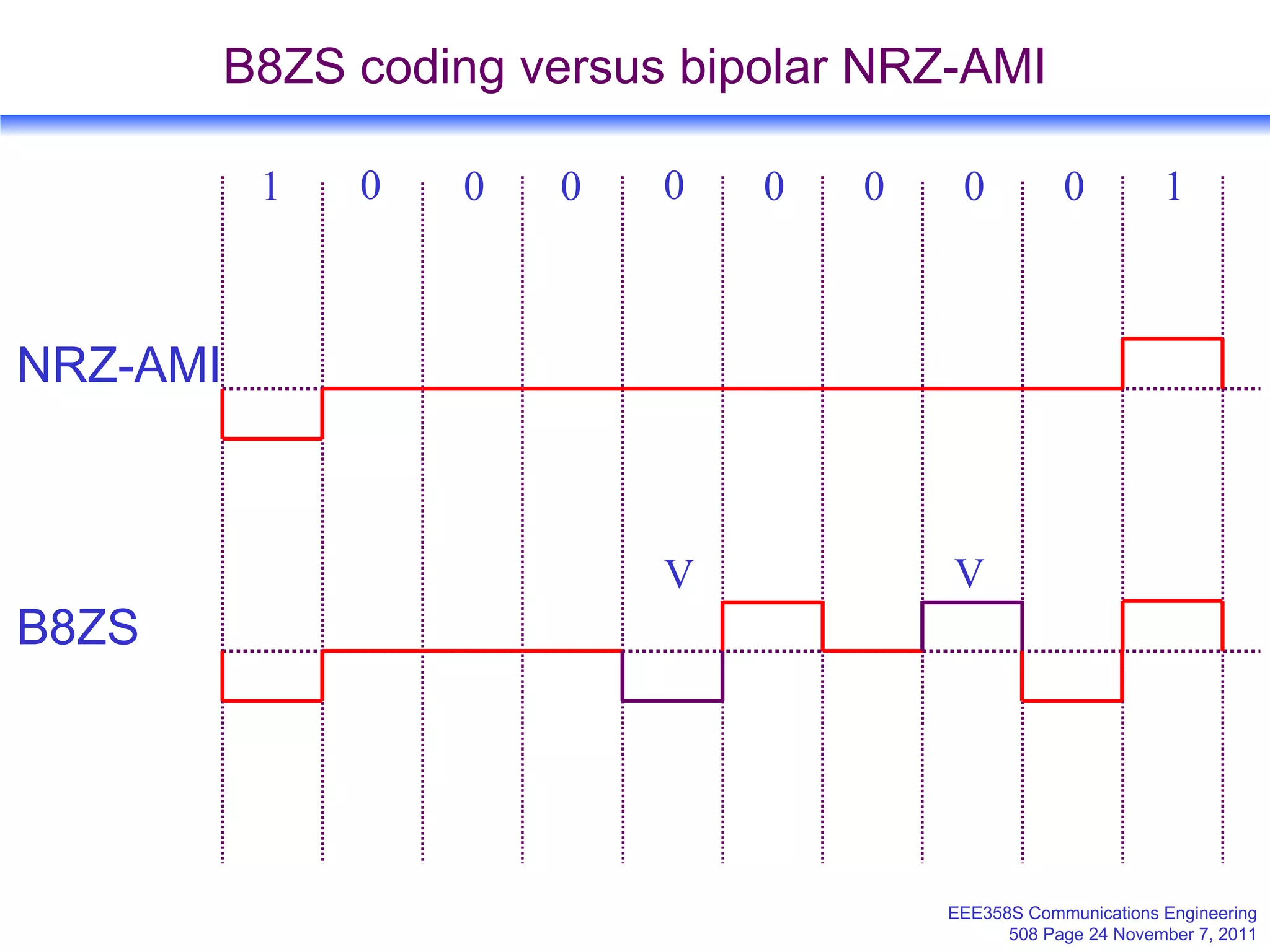
3. Specific encoding methods like alternate mark inversion (AMI) used in telephone systems, and bipolar with eight-zero substitution (B8ZS) used to prevent long runs of zeros in transmission.
![EEE358S Fundamentals of Communications Engineering Pulse Code Modulation Emmanuel O Bejide [email_address] http://www.uct.ac.za/depts/staff/rebejide/ Department of Electrical Engineering University of Cape Town](https://image.slidesharecdn.com/koding-111106230550-phpapp02/75/Koding-1-2048.jpg)