Incoming and Outgoing Shipments in 3 STEPS Using Odoo 17
Ijsea 2nd publication
1. International Journal of Science and Engineering Applications
Volume 2 Issue 4, 2013, ISSN-2319-7560 (Online)
www.ijsea.com 94
Monitoring the Respiratory System using
Temperature Sensor
J.Sheela Arokia Mary
Dept of EEE
KCET, Anna University
Cuddalore, India
R.Divya
Dept of CSE
Mookambigai College of Engg
Trichy, India
Abstract:This paper proposes to monitor the breathing of the patients. The device calculates a patient's breathing rate by
detecting changes in temperature when the patient breathes through a mask. The device includes an alarm through a piezoelectric
speaker which goes off when the patient stops breathing and a low-battery indicator signal when the battery powering the device
reaches a threshold voltage.
Keywords:Thermistor, piezoelectric speaker, threshold voltage, Temperature sensor, breathing.
1. INTRODUCTION
Many biomedical devices, such as commercially available
respiratory monitors, are designed for the developed world
and require a stable power-supply to operate. We
implement a solution that is adaptable to different
environments. Our implementation also includes various
analog circuits for voltage regulation and signal
amplification. Developing a robust and accurate respiratory
monitor served to be a challenging, yet rewarding
experience.
2. METHODOLOGY
An analog-to-digital conversion is used to sample readings
from both the thermistor and the battery, pulse-width
modulation to generate a signal for the speaker, and timers
to switch between tasks.
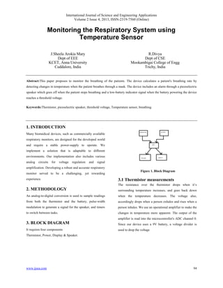
3. BLOCK DIAGRAM
It requires four components
Thermistor, Power, Display & Speaker.
Figure 1. Block Diagram
3.1 Thermistor measurements
The resistance over the thermistor drops when it’s
surrounding temperature increases, and goes back down
when the temperature decreases. The voltage also,
accordingly drops when a person exhales and rises when a
person inhales. We use an operational amplifier to make the
changes in temperature more apparent. The output of the
amplifier is read into the microcontroller's ADC channel 0.
Since our device uses a 9V battery, a voltage divider is
used to drop the voltage
2. International Journal of Science and Engineering Applications
Volume 2 Issue 4, 2013, ISSN-2319-7560 (Online)
www.ijsea.com 95
3.2 Power
Our device can be powered through either a standard AC
power supply or a single 9V battery.
3.3 Display
To conserve power, the user must hold down a button to
turn on the display to read the respiration rate. This
prevents the user fromleaving the display on by mistake
and draining the battery. Breathing rate is measured and
displayed in breaths/min on an LCD. This allows whoever
is monitoring the patient to see if the patient is breathing
too fast or too slowly.
3.4 Speaker
There are two different alarms for our device generated by
a piezoelectric speaker. The first is higher in pitch and
alarms if the patient is not breathing. The second is a signal
that the device is running on low battery. While the first
alarm is a continuous sound, the low-battery alert is a one
second long tone.
4. DESIGN METHOD
4.1 Microcontroller
When choosing a microcontroller for this project, we first
wanted to find the smallest microcontroller possible so that
it could be mounted right onto the device's mask, the
AtMega1284p microcontroller is used.
4.2 Thermistor
Thermistor of smaller size is used, because larger
thermistors could not detect a "breath" nor had a very slow
response time.
4.3 Display
LCD screen is used for display. In order to reduce power
usage, the LCD only receives power when the user presses
the display button, which reduces the load on the battery.
5 SOFTWARE DESIGN &
IMPLEMENTATION
The C programming language was used to program the
MCU using the AVR Studio version 4.15 and was
compiled using the WINAVR GCC C compiler. The
software for the respiratory monitor contains 5 different
tasks and 2 interrupt service routines (ISR). The first ISR is
the Timer0 Compare Match Vector. This ISR activates
every 16.4 ms and decrements three different timeout
counters whenever it activates. It also zeroes the variable
count (used to measure respiration rate) to prevent it from
overflowing. Since the clock of the MCU is 16 MHz, we
set the presale to 1024 and OCR0A to 255. Setting OCR0A
to 255 means the ISR will activate every 256 clk cycles.
The second ISR used was the AC ISR. This ISR activates
when the onboard AC outputs a 1. This ISR was used to
measure the respiration rate of the person.
5.1Thermistor sampling
Samples from the thermistor are taken through PINA0.
First, the ADMUX register is set to turn on the left adjust
result and external reference. The MCU then waits for a
conversion to occur, and then sets the variable sample old
to the current sample and the sample variable to the high
bits from the ADC. The absolute value of the difference
between sample old and sample is used to determine if the
patient has stopped breathing. If this difference is less than
or equal to 8, then this is considered a "no breath". If the
MCU detects 10 consecutive "no breaths", a PWM signal is
generated to produce a sound from the speaker. If the
difference is above the tolerance, then the "no breath"
counter variable c is reset to 0 and the PWM signal is set to
be turned off.
The tolerance for the difference between breaths was found
through experimentation. Looking at the ADC values on
the UART, the range of the sampled values was 6-8 when a
person was not breathing. To compensate for this
fluctuation, we compare the difference between
consecutive thermistor samples against 8 instead of 0. We
also decided to have a counter to keep track of the number
of "no breaths" detected because depending on how a
3. International Journal of Science and Engineering Applications
Volume 2 Issue 4, 2013, ISSN-2319-7560 (Online)
www.ijsea.com 96
person is breathing, consecutive samples could fall into the
tolerance range. Counting up to 10 consecutive "no
breaths" drastically reduces the number of false positive
alarms. DC sampling and PWM signal generation were
concepts we learned earlier in the semester in Labs 2 and 3.
5.2 Battery sampling
To take a sample from the battery, ADC channel 1 on
PINA1 is turned on by setting the ADMUX register. The
MCU waits for a conversion to occur and then sets the
variable bat_samp to the high bits from the ADC. The
sample is then compared to the ADC value that was found
to correspond to a voltage of 7.6 V. During testing it was
found that device operation becomes unstable at 7.5 V.
Therefore, we decided to warn the user when the voltage of
the battery becomes 7.6 VIf the battery sample is found to
be less than or equal to the tolerance, then a PWM signal is
generated, left on for about 1 second, and then is turned off.
The PWM channel which produces a tone for a low-battery
warning has a larger presale than the PWM channel to
produce the alarm for when a patient is not breathing,
making the low-battery tone lower in pitch.
5.3 Display task
The display function is used to display the respiratory rate
on the LCD when the user is holding down the LCD push
button. This was achieved by having the display function
activate when PinB1 was read as 1. When PinB1 is 1 the
LCD is initialized and the value of the respiratory rate
stored in the variable breath rate and written to the LCD
buffer. This value was then displayed on the LCD.
6 CONCLUSION
This paper has comprehensively addresses that the
Piezoelectric speaker is activated when the patient is not
breathing & different sounds are used if not breathing.
Speaker is automatically turned off when the patient begins
to breathe. Hence the device is portable and low cost, can
be used everywhere.
7. REFERENCES
[1] B. Manzanita, C. Lambert and J. de Bie,
"Validation of an ECG-derived respiration
monitoring method", Computers in Cardiology,
vol. 30, pp.613-616.
[2] S. Park, Y. Noh, S. Park and H. Yoon, "An
improved algorithm for respiration signal
extraction from electrocardiogram measured by
conductive textile electrodes using instantaneous
frequency estimation", Medical & Biological
Engineering &Computing, vol. 46, no. 2, pp.
147-1 58.
[3] P. Currishly and Rodriguez-Villegas,
"Breathing detection: towards a miniaturized,
wearable, battery- operated monitoring system",
IEEE Transactions on Biomedical
Engineering, vol. 55, no. 1, pp. 196- 204.
[4] an o -Solar, J.A. Fez and J.
Moreira, "Automatic detection of snoring signals:
validation with simple snorers and OSAS
patients", Proc. of the 22th Annual International
Conference of the IEEE Engineering in Medicine
and Biology Society. pp. 3129-3131.
[5] Z. Zhu, J. Fief and I. Pavlodar," Tracking
human breath in infrared imaging", in
Proceedings of the fifth Symposium on
Bioinformatics and Bioengineering,IEEE
Computer Society Washington, DC, USA, pp.
227-231.
[6] Saatchi, R., Al-Halides, F.Q., Burke, D.,
Delphic, H. " Thermal image analysis of the skin
surface centered on the tip of the nose for
respiration monitoring", Invited paper, IEEE
organized International Conference on Electronic
Design and Signal Processing to be held
between 10th- 12th of December, Mani pal,
India.
[7] R. Murthy, I. Pavlodar and P. Tsiamyrtzis,
"Touch less monitoring of breathing function",
Engineering in Medicine and Biology
Society, 2004. IEMBS'04 26
[8 J. Fein, Z. Zhen and I. Pavlodar, "Imaging
breathing rate in C02 absorption band",
Proceedings of the 2005 IEEE Engineering in
Medicine and Biology 27th Annual Conference,
Shanghai, China, pp. 700-705.
[9] I. Sato and M. Nakajima," Non-contact
Breath Motion Monitoring System in Full
Automation", Proceedings of the 2005 IEEE
4. International Journal of Science and Engineering Applications
Volume 2 Issue 4, 2013, ISSN-2319-7560 (Online)
www.ijsea.com 97
Engineering in Medicine and Biology 27th
Annual Conference, Shanghai, China, pp. 3448-
345.
[10] M. Frijole, J. Amati and J. Pages, "Vision
Based Respiratory Monitoring System",
Proceedings of the 10th Mediterranean
Conference on Control and Automation -
MED2002 Lisbon, Portugal, July 9-12.