Mooc smm substructure_2
•Download as PPTX, PDF•
4 likes•3,685 views

The document discusses the measurement of substructure works according to standard methods. It describes typical substructure elements for different building structures, including pad footings, column stumps, ground beams, and ground slabs. It also outlines the relevant sections for measuring excavation, concrete, brickwork, waterproofing, and summarizes the typical sequence of substructure work.

Recommended
More Related Content
What's hot
What's hot (20)
Similar to Mooc smm substructure_2
Similar to Mooc smm substructure_2 (20)
Recently uploaded
Recently uploaded (20)
Mooc smm substructure_2
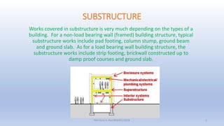
- 1. SUBSTRUCTURE Works covered in substructure is very much depending on the types of a building. For a non-load bearing wall (framed) building structure, typical substructure works include pad footing, column stump, ground beam and ground slab. As for a load bearing wall building structure, the substructure works include strip footing, brickwall constructed up to damp proof courses and ground slab. Nor Azmi A. Bari/BQS401/2018 1
- 2. SUBSTRUCTURE The rules of standard method of measurement in SMM2 for substructure works shall include the following sections: 1) Section D: Excavation and Earthwork 2) Section F: Concrete Work 3) Section G: Brickwork and Blockwork 4) Section K: Waterproofing and Asphalt work The following slides will highlight the salient points involved in the measurement of a simple substructure works. Nor Azmi A. Bari/BQS401/2018 2
- 3. Typical Sequence of work Oversite Excavation Excavation pit (pad footing) or trench (strip footing) Excavation trench for ground beam Disposal of water Disposal of excavated material Concrete work (including blinding/lean concrete, pad or strip footing, column stump, ground beam, ground slab) Brick wall (for load bearing wall) Hardcore Damp proof membrane Nor Azmi A. Bari/BQS401/2018 3
- 4. SECTION D: EXCAVATION AND EARTHWORK Nor Azmi A. Bari/BQS401/2018 4
- 5. SECTION D: EXCAVATION D.9 Volume to be measured The quantities for all excavation works shall be the bulk before excavating and no allowance shall be made for bulking or for any extra space required to accommodate earthwork support, formwork for concrete and working space D.10 Depth classification The depth classification shall be the maximum depth as follows: Not exceeding 0.25m Not exceeding 1.00m Not exceeding 2.00m Not exceeding 4.00m And hereafter in 2.00m stages The depth classification shows the degree of difficulties in excavation which will involve extra cost for support sides of excavation and strutting. D.11 Starting Level State the starting level or the commencing surface , i.e. “ground level”, “reduce level”, “formation level” or other such levels in the description. Nor Azmi A. Bari/BQS401/2018 5
- 6. SECTION D: EXCAVATION Typical excavation work involved in a simple substructure works includes oversite excavation, pit excavation for pad footing or trench excavation for strip footing and ground beam. D.12 Types of excavation D.12.2 Excavation in rock Excavation in rock shall be measured as provisional quantities as the volume of the rock in ground cannot be determined until the excavation work is conducted on site (A.2.1). Therefore, rock can be measured as item rock or alternatively, as extra over item of the various types of excavation. Nor Azmi A. Bari/BQS401/2018 6
- 7. SECTION D: EXCAVATION Types Of Excavation (cont’d) D.12.4 Oversite excavation to reduce level Excavation work to reduce level is measured in m3. This is to reduce the ground level to a predetermined level to allow further construction to be conducted. The measurement is up to the external surface of the outer foundation or footing. When the excavation has been conducted, further excavation such as for footings or ground beam, shall be measured from the reduced level as shown in diagram below. Nor Azmi A. Bari/BQS401/2018 7
- 8. Oversite excavation to reduce level Nor Azmi A. Bari/BQS401/2018 8 Depth classification to maximum depth (D.10)
- 9. Nor Azmi A. Bari/BQS401/2018 9 External surface of the outer foundation or footing
- 10. SECTION D: EXCAVATION Types Of Excavation (cont’d) D.12.6 Pit excavation Excavation pit for pad footing is measured in m3 and stating the number and starting level in the description. If the excavating pits having both dimensions less than 1.25m, shall be measured separately. D.12.7 Trench excavation Trench excavation for strip footing is measured in m3 and the starting level in stated in the description. The overlapping area at internal and external wall junction shall be deducted for the measurement. Nor Azmi A. Bari/BQS401/2018 10
- 11. External surface of strip footing External wall Overlapping area Internal wall Nor Azmi A. Bari/BQS401/2018 11
- 12. SECTION D: EXCAVATION Types Of Excavation (cont’d) D.12.7 Ground beam Trench excavation for ground beam is measured in m3 and the starting level shall be stated in the description. The measurement for ground beam shall be taken from the outer side of column. The overlapping area at every junction between ground beam and pad footing shall not be deducted for trench excavation of ground beam as filling to pad footing will be done up to the starting level. Nor Azmi A. Bari/BQS401/2018 12
- 13. Pad footing Ground beam Overlapping area Column stump Nor Azmi A. Bari/BQS401/2018 13
- 14. SECTION D: EXCAVATION Disposal of Water D.15 Disposal of surface water To ensure that the site and the excavation is free of surface water, an ITEM shall be given for the work. D.16 Disposal of water in the ground Where excavation be conducted below the water level, an ITEM shall be given for keeping the excavation free of ground water. Nor Azmi A. Bari/BQS401/2018 14
- 15. SECTION D: EXCAVATION Disposal of Excavated Materials In excavation works, disposal of excavated material shall be given in m3 and shall be stated in the description whether to be spread on site or to be disposed offsite. D.18 Disposal on site Excavated material to be deposited on site in permanent spoil heaps or spread on site shall be measured stating the requirements for the location or the average distance from the excavation in the description. D.19 Disposal offsite Excavated material to be removed from site shall also be described. D.20 Topsoil Spread on site Topsoil spread on site shall be measure separately from preserved and imported topsoil. Topsoil not exceeding 250 mm thick shall be measured in m2 and the average thickness be stated in the description. If the thickness is exceeding 250 mm thick, it shall be given in m3 (D.26). Topsoil to be reused and deposited in temporary spoil heaps shall be given in m3 and the description shall state any requirement for the location of deposits or the average distance (D.21). Nor Azmi A. Bari/BQS401/2018 15
- 16. Nor Azmi A. Bari/BQS401/2018 16 Commencing level/surface of excavation Pit /trench excavationBack fill Disposal of excavated material
- 17. SECTION D: EXCAVATION Hardcore Hardcore shall be identified as filling to make up levels (D.26). If the thickess of hardcore is exceeding 250mm, it shall be given in m3. If less than 250mm, it shall be given in m2 and state in the dscription the thickness. Material used as hardcore shall also be identified in the description the type and whether to be obtained onsite or offsite (D.23) Nor Azmi A. Bari/BQS401/2018 17
- 18. SECTION F: CONCRETE WORK Nor Azmi A. Bari/BQS401/2018 18
- 19. SECTION F: CONCRETE WORK Insitu concrete Generally, concrete work for substructure shall include for the footings, column stump, ground beam, and ground slab. The construction of reinforced concrete structure comprises of concrete in situ, formwork and reinforcement. The rules of standard method of measurement related to the measurement of concrete work is included in Section F: Concrete Work. Nor Azmi A. Bari/BQS401/2018 19 Column stump
- 20. SECTION F: CONCRETE WORK 1) Pad Footing Concrete for pad footing is given in m3 (F.3.1) and state the number of the footing in the description (F.3.3). The volume of concrete is determined by multiplying the area with the thickness of the footing. For a trapezoidal pad footing the volume is calculated by dividing the area into two simple shape, i.e. cuboid and truncated pyramid. Nor Azmi A. Bari/BQS401/2018 20
- 21. SECTION F: CONCRETE WORK 2) Strip Footing Concrete work for strip footing is given in m3 (F.3.1). The measurement in excavation of strip footing can be used to determine the volume of concrete as the perimeter and the width of the footing is similar for both excavation and concrete work. The thickness of the footing is to be referred to the detailed drawing as it may vary from the depth of excavation. Nor Azmi A. Bari/BQS401/2018 21
- 22. SECTION F: CONCRETE WORK 3) Column Stump Column stump is commonly used together with pad footing to received and transfer loads to foundation/footing. In situ concrete for column stump is given in m3 (F.3.1). The height of the column stump is derived from the top surface of the footing up to the top surface of ground beam as shown below. Nor Azmi A. Bari/BQS401/2018 22 Ground beam Column stump is measured up to the upper surface of ground beam
- 23. SECTION F: CONCRETE WORK 4) Ground Beam Concrete for ground beam is given in m3 (F.3.1). The length of the main beam is taken from column to column. The length for secondary beam is taken up to the sides of the main beam. The volume of concrete for ground beam is derived by multiplying the length of the, the width and the thickness of the beam. Nor Azmi A. Bari/BQS401/2018 23
- 24. SECTION F: CONCRETE WORK Formwork Formwork shall be measured for the surfaces of in situ concrete which require temporary support (F.10.3). Formwork in curve surfaces shall be measured separately stating the radius and the geometrical nature (F.10.7). No deduction for void less than 1m2 (F.10.4). Formwork to sides of footing, including all types of footing, ground slab and ground beam shall be given separately. Formwork shall be given in m2 if the sides is exceeding 1m high. If the height of the side is less than 1m, formwork shall be measured in m and state the high in categories of 250mm, 250mm – 500mm and 500 – 1m (F.11.1). Formwork for ground beam shall be measured from column to column. If there is a secondary ground beam, the length for formwork of the beam is taken from main beam to main beam. No deduction is made for the area of formwork where the secondary beam met the side of main beam. Nor Azmi A. Bari/BQS401/2018 24 Ground beam Ground slab Formwork to sides of ground beam
- 25. SECTION F: CONCRETE WORK Formwork (cont’d) Formwork to sides of column stump shall be grouped as measurement for column and given in m2 (F.15.1). No deduction for formwork at the intersection between ground beam and column stump (F.15.4) Nor Azmi A. Bari/BQS401/2018 25 No ded No deduction for formwork at intersection beam
- 26. SECTION F: CONCRETE WORK Bar Reinforcement Bar reinforcement shall be given in m and the unit of billing is the kg or tonne to the nearest two places of decimals (F.8.2). Particulars of the kind and quality, section of bars (if other than plain circular), tests of bar and restrictions of bending (F.8.1). Bari reinforcement for pad footing, strip footing and ground beam grouped together in one item and classified as foundation (F.8.4a). Bar reinforcement for column stump shall be classified as bar reinforcement in column, beam and lintels (F.8.4j). Bar reinforcement for ground slab shall be classified as bar reinforcement in ground slab (F.8.4b). The length for bar reinforcement of column stump shall include the length extended in column and footing. Nor Azmi A. Bari/BQS401/2018 26
- 27. Nor Azmi A. Bari/BQS401/2018 27
- 28. SECTION F: CONCRETE WORK Fabric Reinforcement Fabric reinforcement shall be given in m2. Particular of weight per m2 and minimum extent of sides and end laps shall be given in the description. (F.9.3). The area measured for fabric reinforcement shall be measured nett no allowance made for laps and voids less than 1 m2 (F.9.2). Nor Azmi A. Bari/BQS401/2018 28
- 29. SECTION G: BRICK WORK AND BLOCK WORK Nor Azmi A. Bari/BQS401/2018 29
- 30. SECTION G: BRICKWORK AND BLOCKWORK Brickwall The rules of standard method of measurement related to the measurement of brick wall is included in Section G: Brickwork and Blockwork. Brick wall constructed on a strip foundation is classified as foundation and measured separately from other brick wall (G.1.1). Brickwall shall be given in m2 and the thickness shall be identified in the description (G.3.3a). The quantity is measured by multiplying the length (centre line) of the wall and the average height of the wall. The height is taken from the upper surfaces of the footing to the damp proof course (DPC). Nor Azmi A. Bari/BQS401/2018 30
- 31. Nor Azmi A. Bari/BQS401/2018 31 Height of brick wall Ground level Strip footing Brick wall
- 32. Nor Azmi A. Bari/BQS401/2018 32
- 33. SECTION K: WATER PROOFING AND ASPHALT WORK Nor Azmi A. Bari/BQS401/2018 33
- 34. SECTION K: WATERPROOFING AND ASPHALT WORK Damp proof course (DPC)/membrane The rules of standard method of measurement related to the measurement of DPC is included in Section K: Waterproofing and Asphalt Work. DPC shall be given in m2 if the width covering exceeding 300mm. If the width covering is less than 300mm, it shall be given in m and state the width in stages of 150mm. The work shall be classified as flat covering, sloping covering 10° - 45° from the horizontal or sloping covering over 45° from the horizontal (K.2.3). The description shall identified the type and quality material, thickness and numbers of coats and layers, nature of base and surface treatment. Nor Azmi A. Bari/BQS401/2018 34
- 35. Nor Azmi A. Bari/BQS401/2018 35
- 36. END OF SUBSTRUCTURE THANK YOU Nor Azmi A. Bari/BQS401/2018 36