
Recommended
More Related Content
Similar to Insructables fm listening bug
Similar to Insructables fm listening bug (20)
More from zubeditufail
More from zubeditufail (20)
Recently uploaded
Recently uploaded (20)
Insructables fm listening bug
- 1. http://www.instructables.com/id/FM-Listening-Bug-Kit/?ALLSTEPS FM Listening Bug by mpilchf amily Download 12 St eps Collect ion I Madeit ! Favor it e Shar e
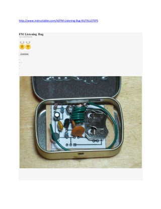
- 2. The on thing every spy needs is a small and w ell concealed listening device. The FM Listening Bug Kit gives you all you need to build a small, single Transistor, FM transmitter that can operate betw een 80 MHz and 150 MHz. Allow ing you to tun it to an open frequency on an FM Radio and listen to w hat is going on in the room you leave that bug in. This bug has an effective range of about 100 meters. In this Instructable w e w ill cover: The Schematic and some basics of how it w orks Parts needed Getting the PCB layout onto a prototyping board (pegboard) Laying out the components on the board Tools needed to assemble the kit Soldering everything together. Remove these ads by Signing Up Step 1:
- 4. As you can see in the schematic below this is a very simple circuit and w ill be an easy build. On thing the Schematic doesn't convey very w ell is w here the Antenna actually needs to be placed. For best results you w ill w ant the Antenna soldered to the first turn on L1. The Antenna should be about 2 inches long Below is the schematic from our friends at Upverter.com. Step 2: Parts List
- 5. Note: A full parts list is attached to this page. Listing the part, manufacture, part number, link to Mouser.com, quantity and price (as of the publishing of this Instructable). Parts List: 1x 22 k Ohm Resistor $0.07 1x 330 Ohm Resistor $0.06 1x 1000 pF Ceramic Capacitor $0.06 1x Omnidirectional Microphone $1.29 1x 1.0 uF Aluminum Electrolytic Capacitor $0.32 350mm (1 foot) of 20/22 AWG Sold copper or Magnetic Wire 1x BC547 Bipolar NPN Transistor $0.07 1x Coin Cell Battery Holder $0.60 1x .022uF Ceramic Disc Capacitor $0.16 1x 47 K Ohm Resistor $0.06 1x 10 pF Ceramic Capacitor $0.08 1x SPST Slide Sw itch $0.37 1x Variable Capacitor 9.8 pF to 50 pF $0.48 1x Dual mini breadboard $2.19 Altoids Smalls Tin CR2032 Cell Battery
- 6. Total cost in parts is less then $7 before shipping. Assuming you already have the w ire and Altoids Smalls Tin on hand. FM-Listening-Bug.xml11 KB Step 3: Pegboard Layout
- 9. When creating a PCB layout from the schematic I kept several elements in mind. 1. PCBs for the layout w on't be available for some time so users need to be able to make this themselves on a Peg board 2. Becuase a Pegboard layout is needed the traces had to be routed on a single side. 3. The w hole project is going to be mounted in an Altoids Tin to conceal it With all that in mind i've included several files so you can either lay this out on a Peg Board or etch your ow n copper clad board. Attached is a zip file containing the PDF and Gerber files needed to produce your ow n PCB. There is a separate PDF file of the layout w ithout the Ground plain filled in. I've also included theFritzing and Eagle CAD files if you w ant to play around w ith the arraignment yourself. If your going the Peg board route then print the PDF file out and cut it to size. Overlay it onto the Peg Board and hold it up to the light to get the component holes lined up w ith the Peg Board's grid. Then tape the layout in place. Be sure the copper grid is on the bottom of the peg board and the layout is taped to the top. Go ahead and take a pointed object like the lead
- 10. from one of the parts and poke out all the component holes. FM Listening Bug PCB files.zip301 KB FM Bug_etch_copper_bottom.pdf3 KB FM Bug.fzz19 KB FM Listening Bug EagleCAD.zip35 KB Step 4: Tools
- 11. Before w e start piecing this together lets gather the tools w e'll need for this. Tools: Soldering iron Solder Needle nose pliers Wire cutters Wire strippers Helping hand/PCB clamp Small flat head screw driver or Probe Solder braid/pump/bulb Magnifying glass Electrical Tape Small Phillips Head Screw driver FM Radio Most of these tools are self explanatory. Of course you need a soldering iron and solder to put the kit together. You'll need a small flat head screw driver or probe to help break any unw anted solder bridges. You can very easily bridge contacts unintentionally w hile soldering the traces. especially w hen you have traces that w ill be very close together like the ones around the Voltage regulator. The magnifying glass w ill come in real handy inspecting your w orkand ensuring there are no unw anted solder bridges. Now to start putting everything together. Step 5: Sizing the Pegboard
- 14. If you plan to place your bug into an Altoids Smalls tin you w ill w ant to trim the board dow n. Trimming it to the same size as the layout sheet is all you need. You can use a pair of w ire cutters to trim off pieces of the board. Or you can use a knife to score the board w here you w ant to break it and use a pair of pliers to break the board. Scoring along one of the row s of holes w ill make it easier to break. I recommend the scoring and snapping method. I used a ruler to line up w here i w anted to score the board. Then i took a box cutter and Scored along the edge of the ruler a couple of times. Then i took my pliers and snapped the edge off. Use a file or 100 grit sand paper to clean up the edges. Then drop it into the tin to see how it fits. Step 6: Placing the Resistors
- 19. We w ill start by placing the resistors on the board. R1 is the 22 K resistor, R2 is the 47 K Resistor, and R3 is the 330 ohm Resistor. All 3 resistor need to be placed stand on end. So take one of the leads and bend it over 180 degrees as show n in the picture above. Place the resistors in there designated spot referring to the reference diagram above as needed. With the resistors in place, bend the leads out so they w ill not fall out w hen you turn the board over to solder them into place. When w orking w ith pegboard like this i like to use the leads of the components to link the traces from one component to another. So bending you leads in the direction of the nearest component they w ill be linked to is a good idea. With the resistors in place flip the board over and solder them in place. Don't w orry about soldering the ends of the leads dow n as traces until w e get all the components in place. But go ahead and use your pliers to bend them around to w here they need to go and cut off any access so its out of the w ay. Step 7: Placing the Capacitors
- 23. Now w e w illplace the capacitors. Pay attention to the polarity of the Electrolytic capacitor (C1). The silver stripe dow n the side of the can is the negative side, (its also the side w ith the shorter lead) and needs to be on the left hand side if your keeping your board oriented in the same w ay the reference image is. You w ill need to fully straighten out the leads to fit in the board correctly. As for the Ceramic capacitors make sure you have the correct ones going into the correct spots. The Capacitors w ill be labeled on there bags but not on the components themselves. So double check the capacitor and w here it goes on the board. C2 - 1000 pF C3 - 10 pF C4 - .022 uF C5- Variable Capacitor
- 24. The variable capacitor is the component w ith the little Phillips head screw in the top of it. The leads of C5 w on't be long enough to bend out. But friction should hold it in place for you w hile you solder the components. The Leads of capacitors C2 w ill need to be straightened like the Electrolytic capacitor. As you can see C4 is a fairly large capacitor. Feel free to insert the leads on either side of the indicated marks. Also the leads of C5 are a bit w ider then indicated on the layout but it w ill fit. Like before bend the lead out a bit in the direction they need to go. Flip the board over and solder the leads into place. Then route the leads and trim as needed. Step 8: Transistor and Mic
- 26. Now w e w illplace the transistor, mic and sw itch. Make sure you have the transistor lined up correctly. As you can see in the reference image the flat side of the transistor needs to be facing to the right. This puts the Emitter on the bottom, Base in the middle and Collector on the top. Bend the leads out a bit and move on to the next component. Feel free to leave the sw itch off if you w ant. It w ill make fitting it into the Atoids Smalls tin a bit easier. I've left off the sw itch here so w e'll need to bridge the solder trace area w here the sw itch w ould be. If you decide to use the sw itch it w ill need it's leads bent in ever so slightly so they w ill fit into the board. The leads of the sw itch w on't be long enough to bend tow ards other components. But friction w ill hold it in place w hile you solder it. The mic w ill drop into place w ithout any issue. Bend the leads as needed and your ready to solder everything in place. Step 9: Making your inductor and Antenna
- 31. Now w e need to create the inductor for the circuit (L1). For this you w ill need a 220mm length of 20/22 AWG sold w ire and a 6mm diameter object like a No 2 pencil. You need to use sold w ire and not braided w ire otherw ise the coil w on't hold its shape very w ell. If you use Magnetic w ire that w ould be best. If you are using standard w ire strip the first 40 mm of insulation off one end. Then you w ill make about 8 turns around the pencil. Keep the turns loose so the turns don't touch each other, unless your using magnetic w ire then you don't have to w orry about it. Leave about 5 or 6 mm at either end of the coil so you can solder it to the board. Put the Inductor in place and solder it in place. Now take a 50mm piece of the w ire and solder one end of it to the 1st turn on L1 near the top of the board. This w ill be your transmitter's antenna. If you are using magnetic w ire then be sure to scrape the coating off the end of the Antenna w ire and the turn you'll be soldering it to before soldering it in place. If you are using regular w ire then strip the end. Wrap the end into a little hook so you can hook it around the first turn and solder it into place. Step 10: Battery Clip
- 35. Finally w e get to the battery clip. In the area of the GND pad on the reference image w e need to create a ground pad for the battery. To do this w e w illuse a couple of leftover bits of w ire about 10mm long. Strip the insulation off the w ire and create 2 U shaped pieces about 5mm w ide in the middle and place them running from top to bottom and side by side in the GND pad area and solder them into place. Now take the battery clip itself and place it on the board so the battery can be inserted into the right hand side of the board. Notice the 2 tabs in the back of the clip. The need to be tow ards the middle of the board. When placing the clip it w ill be a tight fit betw een it and the coil. Solder the clip in place and w e are ready to make the traces. Step 11: Soldering the Traces
- 37. Now starting w ith one component at a time start bending the leads the rest of the w ay over to make contact w ith the components they need to link too. Where you don't have leads to help make your trace start creating solder bridges across the copper pads to the component. It may be a good idea to take some scrap w ire and strip it bear to use as a trace from one component to the next. If you don't like the look of solder bridges on a breadboard then use bits of w ire to go directly from 1 component to the next. Take your time and do one trace at a time. Like they alw ays say "measure tw ice and cut once". In this case check and verify the trace placement tw ice and solder once. Step 12: Wrapping it up
- 41. So there you have it an FM Listening Bug. If you plan to place the bug into an Altoids Smalls tin you w ill w ant to cover the bottom of the board w ith electrical tape to prevent any shorts. It w ould also be a good idea to cover the inside of the tin's lid so nothing shorts out there. If you decided to use the sw itch you w ill need to measure out w here the sw itch w illstick out so you can cut an opening for it in the tin. A 1/4 inch drill bit should be sufficient for making a large enough hole for the sw itch. For best reception you w ill w ant the antenna to be on the outside of the tin so feel free to drill a small hole to allow the antenna to stick out. We only w ant the board to sit in the Altoids tin. It shouldn't be permanently mounted since you w ill have to remove the board in order to change the battery. Of course the board could have been made smaller but then it w ould be difficult to put together as a kit. So there you have it a nice little FM Listening Bug you can use to spy on your friends. Pair this w ith my Electronic Bug Detector Kit and you have a fun little electronic hide and seek game. Create multiple bugs and hide them all over the place. Or you can just use the bug as an FM w ireless mic and have fun playing Radio DJ. NOTE: To date i haven't been able to get this design to actually transmit to an FM radio. I found the original Schematic
- 42. at this w eb site and assumed it w as a functioning design. I used the More Stable design for this project. Maybe the BC547 transistor needs to be replaced w ith either a 2N3904 or a 2N2222. The Coil may also be too big as w ell, but i don't have the available time to troubleshoot the project any further. UPDATE (10/5/2012): I found a problem in the board layout. The transistor is pictured on the layout backw ards. I'll be w orking on a new prototype soon and make sure everything actually w orks before updating the instructable. I'll keep you all posted. http://www.instructables.com/id/Mini-Audio-Transmitter/?ALLSTEPS Mini Audio Transmitter by ThisIsStev e Download 8 St eps Collect ion I Madeit ! Favor it e Shar e
- 46. In this instructable I'm going to show you how to build your ow n portable audio transmitter. This transmits FM w aves so you could easily get the signals on your mobile phone, radios, etc. As the name and the picture indicates it is very small and is approximately the size of a 9v battery clip. This transmitter is like the ones in the movies w hich are used to spy on people or try to record conversations, w ell don't us e this this to spy on anyone, its just for educational purpose only. What does this do? Well all this is a FM transmitter so you could start your ow n mini FM station. I'm going to build a mini FM receiver soon, to go w ith the mini FM transmitter How does this work? Well all of us have heard of "frequency modulation", most commonly know n as "FM", this circuit w orks on the very same principal to transmit audio signals captured by the microphone. This circuit uses BC547 transistor to amplify the signal and then frequency modulate it. Since it is tiny and pow ered w ith just 9v the signal range is limited to only 15m. If you like my project you can vote for me in the battery powered contest.
- 47. OK now enough of the talking and let's start building. Remove these ads by Signing Up Step 1: Tools and Components Like alw ays lets start w ith getting all the parts, the list is quite simple all you need is Components BC547 Transistor An microphone A variable capacitor 47pf An Inductor (see steps for description) 4.7k Resistor 330ohm resistor 1n capacitor (102) 10p capacitor 9V battery
- 48. LED(optional) Tools Soldering Iron An FM receiver (any mobile phone) Step 2: Components
- 49. I got almost all of the components from a pile of old PCBs I had in an old forgotten box. All I had to get w as the BC547 and the electret microphone. Actually I did find the BC547 in an old PCB but i w as not sure if it w ould w ork. It looked quite burnt to me. The old PCBs had many components resistors, crystals, diodes, etc. I may use them some day and for know back in the box. I had to de-solder the parts of the old board, for those w ho don't know how to solder and de-solder there is a bunch of instructables that describe how to do this and learning to solder is not a hard task. Step 3: PCB
- 51. First of all lets start w ith cutting up a PCB to the required size. The size to compare is a 9v battery clip, it might look quite small in the beginning but don't w orry it w ould hold all the components just fine. Use a sand paper for smoothing the sides of the PCB and to clear out any rough edges. Make sure to get a PCB w ith big holes as the variable capacitor pins w on't go in the standard size holes. Step 4: Microphone
- 53. You can get the microphone at a local hardw are store. And be sure to get some male pins to hold the microphone in place refer the picture as to how to solder the microphone in place. Why not use some wires to hold the microphone? I w ould not suggest w ires as w hen you tape the circuit if the last few steps you w ould not get a clear audio. I tried it and got a lot of noise. I got lesser noise w hen I used the male pins soldered to the microphone. Step 5: Circuit
- 56. Once you're done w ith the PCB and know w here and how to solder the microphone now it's time to complete the rest of the circuit. Follow the circuit above and solder all of the components. Make sure not to leave any space betw een any of the components if you need to get the circuit small. For the inductor use 0.5mm w ire and 8 turns, w ith each turn w ith a diameter of 6mm. And for the antenna just use a thin 5cm long w ire. For more stability you could center tap the coil and solder the antenna to the center tap. Also If you notice the circuit has a LED in it, it is used to show w hen the circuit is functional. I did not add the LED in my circuit because it w as draining my battery faster. Step 6: Taping Time
- 59. Once you got the circuit like the one in the above picture, it's time to cover it w ith tape. I used w iring tape to cover the w hole circuit except the microphone and the variable capacitor. This is an important step as w hen you proceed to the next step, w here you tune to the required bandw idth. Touching the circuit (mainly the coil) with your fingers would lead to severe noise. You could also use a heat sink instead of tape, I used tape because I w anted to experiment w ithe circuit so I did not w ant it to be permanent. Step 7: Tuning to the required bandwidth
- 60. Now it's time to tune the circuit to a required bandw idth, you could do this in tw o w ays. 1. Use your mobile phone to find the signal 2. Manually tune the variable capacitor to match a frequency The first step is recommended all you have to do is pow er the circuit and turn on auto find bands on your mobile. Your mobile w ould scan for channels and all you have to do is look for your transmitter (play some music in front of the transmitter) on that list. The second method is time consuming, in this method you have to turn on your radio and the circuit. Keep the radio at a specific channel, and then tune the variable capacitor extremely slow ly. When you hear stuff on the radio maybe a song that you are playing stop and the bandw idth on the radio is the required bandw idth. Step 8: Re-Chargeable version
- 61. After using the 9v battery circuit for some time I thought of replacing the battery w ith rechargeable Li-ion batteries. If you have view ed my previous instructables you w ould have seen that I use these batteries a lot. The rechargeable batteries provide longer transmission than the common 9v battery. If you liked this instructable then you w ould also like this one. http://www.instructables.com/id/The-Ultimate-FM-Transmitter/?ALLSTEPS The Ultimate FM Transmitter (Long Range Spybug) by ASCAS Download 15 St eps Collect ion I Madeit ! Favor it e Shar e
- 64. Have you ever w anted to broadcast your ow n radio station w ithin your neighborhood? Ever get curious on w here people get those "Surveillance Bugs" from spy and action movies? This small and simple FM transmitter is the toy that geeks have alw ays w anted. FM transmitters can be complicated to build, that's w hy I'm teaching you how to make a foolproof FM transmitter. There's no need to buy kits, this tutorial includes the PCB layout and the schematics. It has a range of up to 1/4 mile or more. It's great for room monitoring, baby listening and nature research. My Experience: FM transmitters remind me of my early years in electronics. When I w as 8, I came across Art Sw an's FM transmitter circuit. At the time I had no idea of w here I'm supposed to buy the parts, so I recycled mine out of junk. I guess the biggest struggle that you're going to face is finding a trimmer capacitor. I'll give some tips on the last step of this instructable. In a nutshell, I highly recommend this project for everyone and also those w ho are still new in electronics. >>>>>>>WARNING: You may experience nostalgia! :D<<<<<<< Technical Specifications: - 1/4 Mile Radius Range -Pow ered By A 9V Battery - Lasts For Several Days - Adjustable 87-108MHz Please Watch: Celebrating the 1st episode of my new YouTube channel! It's my first time to document a project w ith videography. I hope you guys enjoy the vid! Please leave a comment below , I w ould appreciate some advise regarding the video. Disclaimer: This project is for educational purposes only and is not intended to air/ interfere w ith present radio channels. Neither site nor I, am liable for careless actions. Please check for the legality before attempting the project w ithin your area. As long as Free PDF E-Book Download.pdf1 MB Remove these ads by Signing Up Step 1: Gather The Parts
- 65. All of these are available on any branch of RadioShack! :) ______________________________
- 66. MISC: - Copper Clad PCB/ Perfboard - Solid Gauge # 18 Wire - Electret Microphone - ¼" Bolt ______________________________ Transistors: - 2N3904 General NPN Transistor (2x) ______________________________ Capacitors: - 15pF or 40pF Trimmer Capacitor - 100nF Ceramic Capacitor (2x) - 10nF Ceramic Capacitor - 4pF Ceramic Capacitor ______________________________ Resistors: - 1M Ohm ¼w Resistor - 100K Ohm ¼w Resistor - 10K Ohm ¼w Resistor (3x) - 1K Ohm ¼w Resistor - 100 Ohm ¼w Resistor ______________________________ Tools: - A Pair Of Pliers - Soldering Iron - Hot Glue Gun Step 2: PCB & Schematics
- 68. I designed a compact PCB layout for Art Sw an's miniature FM transmitter circuit using Fritzing. Use this step as your reference for the assembly. _________________________ About The Circuit: These is the exact description of Art Sw an, the circuit's Author, "This miniature transmitter is easy to construct and can be picked up on any standard FM receiver. It has a range of up to 1/4 mile or more. It's great for room monitoring, baby listening and nature research" _________________________ Download Link: https://docs.google.com/file/d/0Bw P5mrDBOvNYaHFnME... PCB_Layout.pdf2 KB Step 3: Print The PCB Layout
- 71. Dow nload the PDF file then print it w ith your printer's standard setting then cut the printed layout. Be careful w hen cutting, the tip of my thumb got sliced by the sharp cutter blade. _________________ Download Link: https://drive.google.com/file/d/0Bw P5mrDBOvNYaHFn... PCB_Layout.pdf2 KB Step 4: Develop The PCB
- 73. I'm using something w hat's called presensitized PCB fabrication, it's different from the toner transfer method. If you're not familiar w ith presensitized PCBs, better go w ith the toner transfer method. ___________________________
- 74. Presensitized PCBs: I expose mine directly to a 10W fluorescent lamp for 5:20 minutes then use a dilute solution of Sodium Hydroxide to develop the exposed PCB. ___________________________ Here's a separate tutorial for the PCB fabrication: Step 5: Etch The PCB
- 75. Pour Ferric Chloride on a plastic tray then start to etch the PCB. Step 6: Clean The PCB
- 76. Use a sw ab and Acetone to remove the photo-positive layer/ toner. Step 7: Solder The Components
- 78. Show All 7 Items Use step #2 as your reference. Solder the smaller parts first. Start w ith the resistors, the capacitors, the transistors, the coil, the antenna then the 9V cattery clip. Step 8: Construct The Coil
- 79. Strip a solid gauge #18 w ire. Use a 1/4" bolt then turn the w ire 7-8 times. Step 9: Adding The Antenna
- 81. Solder a hook-up w ire to the antenna pin, it's located on the 2nd transistor's collector pin. Use a maximum of 8 inches an a minimum of 5 inches. Step 10: Recycle A Battery Clip
- 83. The key to this compact transmitter is the ingenious battery clip.You can get one by dismantling an scrap 9v battery. Step 11: Glue Them Together
- 84. Apply a generous blob of hot glue to hold the clip and the transmitter circuit together. Step 12: Breadboard Version
- 86. Recently, people have been asking me if it's possible to make this project w ithout having to fabricate a PCB. The answ er is yes. In fact I built my first FM transmitter on a perfboard. I guess some are new to this, no w orries I'm here to teach you. ________________________ The answ er to this is a "Perfboard/ Prototype board. It's a PCB designed for prototyping circuits. There are three types of
- 87. perfboards, the one that suits our needs is the dot matrix version. If you're new to this, make magazine has handy YouTube tutorial. Step 13: Tune The Transmitter
- 88. Turn on your radio then tune it to your desired channel frequency. You'll get more range from the vacant channels. Don't touch the coil, just turn the trimmer capacitor until you hear a feedback from the radio. Step 14: Q&A - Tips & Tricks
- 89. Where Can I Buy The Parts? If you live in the US, all the parts that I've used are available from Radioshack. You don't believe me? The parts from my first non-recycled transmitter came from RadioShack, Long Island, NY branch. Any Alternatives For The Trimmer Capacitor? Most likely, you'll find one from a scrap transistor radios how ever you can replace it w ith a 20pF ceramic capacitor then rely on the coil's adjustment for compensation. Trimmer caps are color coded, only use the Red, Green or Yellow . I used the yellow since it covers a w ider range. Which Wire Should I Use? Only use solid w ires that has a thickness of 18 - 22 gauge. When I w as still a novice hobbyist, I w as w orried about the strict selection of parts. Don't w orry too much, eventually you'll learn to improvise w hen parts are not available. Why Does The Frequency Change After Tuning? Let's admit it, tuning the radio is a bloody challenge! If you use a metal screw driver to tune the trimmer cap, chances are you'll end up having a different frequency broadcast the moment you lift the screw driver. This is w hy non conductive screw drivers are recommended. Where Can I Find A Non-Conductive Screwdriver? You'll easily find one from a PC repair shop, or maybe form a hardw are store. If you really can't find one, the famous Little Bits kit comes w ith it. Is It Possible To Connect A 3.5mm Audio Jack? Yes, it's possible! All you need to do is to link the common ground then solder a 1K ohm resistor each channel (L & R) forming a junction. Now solder a w ire from the junction to U1's collector pin (refer to the schematic). You can now connect your MP3 player! I'll post an additional step regarding this mod. Can I Hook This On A 12v Car Battery? This project w ould still operate at voltages betw een 7v-14v, so yeah it's compatible. If you w ant to stay safe and prevent the circuit from burning, solder a 10 ohm resistor in series w ith the FM transmitter and 12v battery. Is This Legal? As long as you don't use it to spy on others and not use a long & huge antenna then yes, it's legal. Just don't use it near an airport. For more info, pleas read theFCC Rules.