SlideShare a Scribd company logo
1 of 9
An inside look into the planning
  requirements of an MRL Lift
                                     by Samson Rajan Babu
        IAEE Affiliate member, CIBSE Senior Vertical Transportation Engineer, Burt Hill - Dubai

Introduction                                                         Unless the ‘special requirements’ of a MRL lift are
“Machine room less” (MRL) lift concept has brought                   understood and allowed for in a building design,
in a great design flexibility for the architects. MRL                one may not receive a lift installation that is reliable
lift concept has greatly helped in space savings,                    and safe: to use, to rescue and to maintain. This
construction cost savings, energy savings and                        article addresses unique issues that need to be
environmental friendliness.        MRL concept has                   contemplated during building design, while planning
contributed in the development of modern technology/                 a MRL lift.
products such as compact gearless machines and
                                                                     General Arrangement
slim control panels.
                                                                     The majority of the modern MRL lifts consist of
However, it should be noted that a MRL lift is a “special
kid” requiring special attention and environment. For                traction machines, placed within the lift shaft and
a MRL lift to perform as efficiently, safely, reliably as            an emergency control panel, preferably placed at
a regular lift with machine room, it requires additional             the top landing, adjacent to the landing door. The
considerations from various professional disciplines                 variable frequency controller, emergency battery
such as: Architecture, structural, mechanical,                       rescue controllers and additional group controller are
electrical and life safety.                                          placed within the head room space. Recent trends
                                                                     allow the emergency control panels and other control
A single, low rise MRL lift project with minimal
interaction with the ‘authority having jurisdiction’                 panels to be located away from the top landing, in
(AHJ) might be easy to execute without much                          a dedicated closet. The closet could be positioned
hassle. However, a large scale, high profile project                 up to 5mtrs. away from the top landing or it could
with intense participation and scrutiny of the AHJ                   be positioned up to 1 floor below the top landing.
must be planned carefully in order to accommodate                    Traction machines are compact, low speed, gearless
all interfacing requirements and performance                         ‘permanent magnet synchronous motor’ (PMSM)
requirements mandated by such project.                               driven machines usually arranged in 2:1 roping.


                                                                                 (b) Emergency control panel built inside
  (a) Emergency control panel beside the entrance at top floor
                                                                                      the hall call station at top floor


                                Fig1: General arrangement of emergency control panel for MRL lifts .


Page 52 - ELEVATION - i64                                                                    www.elevationdirectory.com
An inside look into the planning requirements of an MRL Lift

Range of application                                          geographical locations (such as the Middle East),
                                                              where high temperatures and water condensation
MRL lifts are commonly available up to 1600kgs
                                                              is a problem. Further more, cooling and ventilating
capacity and up to 1.75mps speeds. Greater capacities
                                                              the head room space is a must when technicians
are possible but with appropriate reduction in speed
                                                              are required to spend a long time inside the lift shaft
(for example: 2500kgs with 1.0mps speed). They
                                                              trouble shooting the lifts.
are used in all service conditions (i.e. passenger/
service/hospital/freight). MRL lifts support both wide        This calls for ducted cooling in to the head room space
and deep car configurations with center opening or            along with humidity control. While the mechanical
side opening doors. MRL lifts can be provided in              engineer designs the cooling requirements and
single entrance and double entrance configurations.           cooling duct sizes (based on the heat rejection
                                                              data from the lift supplier), the location of this duct
Emergency control panels
                                                              opening must be approved by the lift manufacturer
Predominantly, these are slim type panels preferably          so as not to clash with other lift equipment.
located adjacent to the landing door at the top
                                                              Further, it is recommended to have temperature
landing and are used only for rescuing/trouble-
                                                              sensors within the head room space to stop the lift,
shooting purposes. These controllers can be a
                                                              should there be an ‘overheating’ condition detected
separate panel or can be built-in to the rear side of
                                                              in the head room space.
hall call stations at top floor. (Fig.1).
                                                              Temperature and Humidity control at lift lobby
Fig.(2) shows an emergency control panel built
into the rear side of a hall call station. It may be          Ideally, the emergency control panel is placed
noted here that the hall call station at the top floor        adjacent to the top floor landing. This is acceptable
is considerably ‘taller’ than the hall stations at other      assuming there is enough air-conditioning at the
floors in order to accommodate additional control             top floor lobby in order to maintain the temperature
buttons and indicators. This often mandates using             range and humidity conditions. In case there is no
different types of hall call stations used on a single lift   air-conditioning available at the top floor lobby, in
group installation. The hall call stations at the top floor   hot and humid climates, due to excessive heat and
may not match the hall call stations at the other floors.     water condensation, the controller could malfunction;
                                                              electronic components could fail.
Maintenance activities at the top floor
                                                              Devices for emergency operations
Since the entire machinery is located at the top of the
lift shaft and the emergency control panel is located         To carry out emergency rescue operations from the
at the top floor, any rescue, maintenance or trouble-         emergency control panel, the majority of the MRL
shooting operation must be performed from the                 suppliers provide display devices to give indication
top floor level. Depending on the situation, service          of direction of movement and the car reaching
technicians may require access to the top floor and           unlocking zone such as directional arrows, LED door
may be required to remain there for extended hours.           zone indicators. Other manufacturers provide ‘rear
This must be considered while planning penthouses             vision panels’ (instead of directional arrows) to catch
or executive offices at the top floors as it could            an actual glimpse of the machinery/rope movement.
become a considerable disturbance to the high-
                                                              Such vision panels would be useful only if the
profile occupants.
                                                              emergency control panel is located within the lift
Temperature and Humidity control at head room                 shaft frame. It is critical that this vision panel exactly
space                                                         aligns with the moving equipment inside the lift shaft.
                                                              If the control panel is not aligned or if it is moved
Even though MRL lifts come with latest compact
                                                              away from the lift shaft, then the ability to watch
PMSM gearless machines, the temperature and
                                                              the machinery/rope movement is lost. Under such
humidity requirements have not changed from that
                                                              circumstances, without directional arrows, it may be
of lifts with machine room. Now that we have even
                                                              necessary to install a CCTV camera to display rope
more cramped space and the busy machine/drive
                                                              movement at the emergency control panel.
continuously releasing heat, the small head room
space could heat up quickly and there should be               Note on emergency control panels built-in to hall
an engineered way to cool the head room space                 call stations
and maintain the humidity within acceptable limits.
                                                              Fig. (2) shows an emergency control panel built-in
This may not be a problem for MRL lifts installed at
                                                              to the hall call station. When 2 or more lifts are in
locations with colder climates.
                                                              a common shaft, often a combined hall call station
However, this is very essential for hot and humid             is used. Under such circumstances, the equipment


Page 54 - ELEVATION - i64                                                           www.elevationdirectory.com
An inside look into the planning requirements of an MRL Lift


                                     Figure 2: Emergency controls built-inside hall call station


layout should be carefully organised so that the rope                To mitigate this risk, ‘inching’ method (i.e. opening
movement of ‘each lift’ in the group is visible through              the brake for a max of 23 seconds) is recommended
the vision panels on the combined hall call station. If              during rescue. However, should there be trouble
not, additional hall call stations may be necessary in               with the brake movement (mechanical or electrical)
order to achieve visibility of rope movement for each                or should the brake fail to close in again or should the
                                                                     technician not be alert, it is even more likely that the
lift in the common shaft. (Fig. 3) Alternatively, CCTV
                                                                     sheave might ‘free-wheel’ uncontrollably. When this
cameras inside lift shaft and/or directional arrows on
                                                                     condition occurs, the car can reach an ‘over speed
the controller shall be utilised to ascertain direction              condition’ and the safety gear will be deployed. This
of car movement.                                                     is a major event, which should be avoided in regular
Self induced dynamic braking a.k.a. Rush-away                        rescue operations.
(free wheel) protection                                              In order to prevent the lift car from reaching an over
In the absence of a gear box, there is less friction                 speed condition, ‘self induced dynamic braking’
                                                                     feature is necessary with the motor of a gearless
in a gearless machine and it can rotate freely with
                                                                     machine. With this feature, during overhauling
the slightest torque. When the brakes are opened,
                                                                     conditions, the motor develops a torque opposite
depending on the heavier side, the machine sheave                    to the direction of rotation of the motor, which
tends to ‘free-wheel’ and the lift car could reach an                helps in reducing the free-wheel speed. This goes
over speed condition. With large capacity lifts, the                 on continuously until the speed (and the dynamic
counterweight and the car weight are so large that                   braking torque) is reduced to a safe level for the car
controlling their movement manually is a difficult task.             to hit the buffers in the pit.


                             (a)                                                                     (b)

                                                        Fig 3: Configurations
              (a) would require two separate hall call stations to view rope movement through vision panel. It will be
               possible to view both lifts’ rope movement through a combined hall call station with configuration (b).


Page 56 - ELEVATION - i64                                                                      www.elevationdirectory.com
An inside look into the planning requirements of an MRL Lift


                                                                                            Half-thick RCC
                                                                                              front wall

             Maintenance access panel fully                                       Maintenance access panel
            recessed into front wall affects fire                               partially recessed into front wall
               rating of hoistway/entrance                                           preserves fire rating of
                                                                                        hoistway/entrance

                                 Fig 4: Arrangement of emergency control panel within lift shaft frame.


Fire rating integrity at top floor
Fire rated lift shafts with fire rated entrances require
extensive planning with respect to installing the
landing door frames and fire sealing the entrance.
However, when the lift controller is placed adjacent to
landing door at top floor (within the front wall), in order
to maintain the fire rating integrity of that floor, the
emergency control panel must be ‘fire rating certified’
(such as UL UK, CSA) and the complete entrance
(together with door jamb and the emergency control
panel) must be fire sealed using methods authorised
by a fire protection specialist. Alternatively a half-thick
fire rated front wall can be built behind the controller,
while the controller partially projects from the front wall
(Fig. 4). Otherwise, the controller should be moved
out of the fire rated lift shaft frame; this could cause
inability to watch the rope movement and solutions as
described above should be adopted.
Space for additional controllers
In addition to the lift controller, there are other
control panels such as: the VF drive, emergency
battery drive, group controller (for 3 and more lift
groups), which also need space and they must
be located somewhere on the building plan. Many
manufacturers install these panels inside the lift
shaft in the head room area (Fig. 5). Temperature
and humidity control in the head room area is critical
                                                                         Figure 5: Additional control panels inside head room space:
in order to provide habitable surroundings for these                            control panel, braking resistor unit, automatic
control panels.                                                                          rescue device, battery bank.


www.elevationdirectory.com                                                                    i64 - ELEVATION - Page 57
An inside look into the planning requirements of an MRL Lift

                                                                      Rescue operation from top floor lobby (with
                                                                      power)
                                                                      When the power supply is still available and if a lift
                                                                      car has stopped in between floors due to malfunction,
                                                                      rescue operation has to be carried out from ‘emergency
                                        Emergency control panel       control panel’ at the top floor lobby. The lift car is
                                         in stainless steel finish.   moved in ‘maintenance mode’ by pressing up/down
                                                                      until the car reaches floor. Door zone indicators,
                                                                      directional arrows and a beep should be provided on
                                                                      the ‘emergency control panel’ to indicate that the car
                                                                      has reached the door opening zone.
                                                                      Rescue operation from top floor lobby (without
                                                                      power)
                                                                      When there is a power failure and if a lift car has
                                                                      stopped in between floors, the rescue operation has
                                                                      to be carried out from ‘emergency control panel’ at
                                                                      the top floor. The electro-mechanical brakes on the
  Emergency
                                                                      traction machine must be opened either electrically
control panel in
                                                                      or manually.
 custom made
shape & finish.                                                       For releasing brakes electrically, stand-by power
                                                                      supply, such as batteries, must be provided to open
                                                                      the brakes. Battery power is required also for the
                                                                      ‘emergency control panel’ to power the door zone
                                                                      indicators, directional arrows and beep sounds.
                                                                      Batteries should be of ‘rechargeable type’ and the
      Fig. 6 Visual impact of controllers at top floor lobby.         availability of stand-by power supply as well as the
                                                                      recharging circuit of batteries must be monitored
                                                                      24x7 with suitable alarm signals to indicate any
Visual impact of controllers at top floor                             trouble with ‘recharging’.
When controllers are placed adjacent to the top                       Alternatively, the brakes can be opened mechanically
landing door or on a main lobby, the aesthetics                       using a ‘Bowden cable’ connecting the release lever
and finishes of the control panel enclosure must                      to the brakes. The Bowden cable is routed through
be reviewed. There shall not be any screws or                         pulleys and its proper movement must be checked
ventilation slots on the control panel visible at the                 regularly to ensure its proper operation. Location
lobby. It shall only present a smooth continuous                      and anchorage for such pulleys must be finalised in
surface just like a door jamb. The control panel door                 consultation with the supplier.
handle and lock shall be discreetly designed. The                     Rescue operation from top floor lobby (balanced
surface finish of the control panel (on all exposed                   loads)
sides) shall be verified to be compatible with the
                                                                      During a rescue operation (with or without power),
lobby finishes. For special projects, the controllers                 the brakes are opened and the car usually moves up
can also be fabricated in special shapes to achieve                   or down depending on the load condition within the
a homogeneous lobby elevation at the top floor (at                    car. However, there could be situations where the
additional cost) (Fig. 6).                                            car load and the counterweight are equal and there
                                                                      is no torque on the sheave to move the car. Under
Noise level at top floor
                                                                      such conditions, the sheave may need external
Traction machines inside the lift shaft create                        agitation to induce movement to the main sheave.
considerable amount of audible noise when the                         External power supply is required from a stand-by
brakes drop and release. The VFD drive (usually                       power source such as rechargeable batteries to
placed within the head room space) also creates                       cause the agitation. In case the car does not move
                                                                      even after agitating the sheave, then technicians will
audible motor noise. Also there is relay switching
                                                                      be required to reach into the lift shaft to move the car
noise from the control panel at the lobby. The                        by external force (see ‘Access into head room space’
noise level of this equipment must be ascertained                     below). Usually, weights are added to the car top to
especially for quiet applications such as clinics,                    cause load imbalance and to effect car movement.
hospitals, schools, conference rooms and executive                    Sometimes mechanical rope pullers are used to
offices.                                                              move the car.


Page 58 - ELEVATION - i64                                                                  www.elevationdirectory.com
An inside look into the planning requirements of an MRL Lift

Access into the head room space                                   especially for the head room space (this condition
                                                                  is very similar to pit partitions, which protect the
Even though MRL lifts have the design provision
                                                                  operatives from the moving parts of the other lift, at
to carry out rescuing from the top floor lobby, there
                                                                  the pit level). Such partitions also prevent movement
are numerous occasions when technicians would
                                                                  of technicians from one lift shaft to the adjacent lift
need access into the head room space. Such as
balanced car, maintenance and trouble-shooting of                 shaft, which could be very unsafe.
machines, VFD and other controllers inside the head               However, if the horizontal distance of the edge of a
room space.                                                       lift car roof is less than 500mm from moving part of
Usually the car top is utilised as the access platform            an adjacent lift, then a full height lift shaft partition
to carry out maintenance/repair procedures inside                 shall be provided as per EN81-1.
the head room space. However, if the car is far below             Ascending car over speed protection (ACO)
the head room space and if it cannot be moved, then
exclusive access ladders and working platforms will               The modern variable frequency controlled MRL lifts
be required inside the head room space. Usually,                  come with gearless machines, which utilise electro-
these are deployed / removed through the top floor                magnetic brakes (acting on main sheave) to stop the
entrance.                                                         car during emergency. These brakes also hold the
                                                                  sheave in position once the variable frequency drive
However, if the car has stopped at the top floor due to           has stopped the motor. The EN81-1 code requires
a malfunction and if it cannot be moved, alternative              that any lift car should be protected against over
access doors into the head room space are required.               speeding in ‘upward’ direction too. Separate means
The MRL lift design should incorporate access                     for this ACO protection must be provided within the
ladders and platforms that are easily deployed and                lift package.
removed to facilitate such work.                                  Alternatively, the EN81-1 code allows the electro-
Partitions at the head room space                                 magnetic brakes on the gearless machine to be
                                                                  utilised for providing ACO protection: provided there
When two or more MRL lifts are installed within a                 is built-in redundancy and when correct operation
common shaft, the technicians may be required to                  is monitored. It must be ensured that there are
perform rescuing or trouble shooting works on one                 dual disc brakes on the traction machine with 100%
lift in the head room space while the other is still in           mechanical redundancy (Fig. 7). If not, external
working condition.                                                braking devices such as rope brake or sheave brake
In order to protect technicians working inside the head           or spring loaded guide rail brakes or a bi-directional
room space, lift shaft partitions are recommended                 safety gear will be required.


                               (a)                                     (b)                                             (c)


                               (d)                                     (e)                                             (f)

            Fig 7: (a) Gearless machine with dual electro-magnetic brakes (b) Rope brake (c) Rope brake installed on
                    a geared traction machine (d) Sheave brake (e) Rail brake (f) Bi-directional car safety gear.


Page 60 - ELEVATION - i64                                                                  www.elevationdirectory.com
An inside look into the planning requirements of an MRL Lift

Bi-directional over speed governors for ACO
In order to detect an ‘ascending over speed
condition’, a bi-directional over speed governor
or a similar device will be required. This type of
governor detects over speeding in downward as
well as upward direction. It must be ensured that
the MRL lift is provided with ‘bidirectional governor’
or other means to ‘detect over speed in upward
direction’. For the ‘downward over speed’ condition,
the governor activates the progressive safety gear
mechanism, while the ‘upward over speed condition’,
the governor only generates a signal to operate any
of the disc brake / rope brake / spring loaded guide       Fig 8: Detector mechanism for unintended car movement.

rail brake.
                                                         Sometimes, the disconnect switches are located
Unintended car movement protection (UCM)                 above the false ceiling level of lift lobby (Fig. 9).
                                                         This is acceptable provided there is quick and easy
As per EN81-1, any lift car should be protected
                                                         means to access the switches. Often, it is proposed
against ‘unintended car movement, when the doors
                                                         to install the disconnect switches inside the head
are not closed’. Separate means for this UCM
                                                         room space. This may present a problem in case
protection must be provided within the lift package.
                                                         the car has stopped at the top floor level due to a
Alternatively, the EN81-1 code allows disc brakes
                                                         malfunction.
on the gearless machine to be utilised for providing
UCM protection; provided there is built-in redundancy
and when correct operation is monitored. It must
be ensured that there are dual disc brakes on the
traction machine with 100% mechanical redundancy.
If not, external braking devices such as rope brake or
sheave brake will be required.
Rope movement detector for UCM
In order to detect ‘unintended car movement’, a
standalone rope movement detector with a dedicated
controller will be required.
Usually, it is a roller in pressure contact against
one of the main rope. (Fig. 8) When the main
rope moves, the contact roller also moves. This
information is verified by the dedicated controller
against the door open or close condition. When there
is abnormal rope movement (other than normal rope
                                                                Fig. 9: Disconnect switches & interface modules
stretch) (typically more than 150mm) when the doors
                                                              located above gypsum ceiling level at the top floor.
are open, the controller activates the safety brake
and also removes the main power supply. It must be       Communication devices within head room space
ensured that the MRL lift is provided with this rope
                                                         For rescuing and trouble-shooting purposes, suitable
movement detector and control mechanism.
                                                         communication devices (such as an intercom)
Disconnect switches                                      should be provided within the head room space.
The 3-phase and 1-phase disconnect switches for          This will enable proper communication between the
the MRL lifts should be located outside the lift         technicians inside the lift shaft and the passengers
shaft in order to carry out rescue/maintenance           trapped inside or another technician inside the car.
tasks. The switches should be located very close         Fire and Life safety related issues
to the lift shaft and should be easily reachable. If
architecturally clean lobbies are required at the top    On a large, specialised project involving extensive
floor, the disconnect switches may require cabinets      fire and life safety requirements, specialised
with suitable surface finishes.                          services such as lift shaft pressurization and lift shaft


Page 62 - ELEVATION - i64                                                       www.elevationdirectory.com
An inside look into the planning requirements of an MRL Lift

ventilation are required (these are not related to the
‘ducted air-conditioning’ provided at the head room
space for the machinery). These services require
additional openings on the lift shaft wall at the head
room level. While the mechanical engineer designs
the pressurization/ventilation requirements and the
duct sizes, the location of these duct openings must
be approved by the lift manufacturer so as not to
clash with other lift equipment (Fig. 10). It could be
an easier task to provide such openings and related
ducting works for MRL lifts, which travel the full
height of a building. However, these tasks become
complicated when a MRL lift does not travel the full
height of the building up to the top floor.
Interfacing enhanced features on MRL lifts
Large and specialised lift projects often involve                           Fig. 10 Additional mechanical openings
enhanced operational features, such as card reader                                 at the head room space .
access, CCTV monitoring, fire alarm interface,
public announcement, background music, building                 Lift shaft structure provisions
management system interface, video displays and                 The traction machine of a MRL lift could be supported
EPABX telephone systems. Wiring from/to each of                 either on machine support beams or on car guide
these features requires to be connected to/from the             rails. The machine beams are usually anchored
lift controller at the head room space. Often, there            and/or embedded into the lift shaft walls. When
are individual interface controllers from each of these         supported on car guide rails, additional anchorages
systems, which are traditionally placed in the machine          on the lift shaft wall are required at the head room
room. For example, a card reader system has input/              space. Due to the 2:1 roping employed with MRL
output module and a LCD display system has an                   lifts, there is also a rope hitch beam anchored and/or
encoder board. Without a machine room, the space                embedded into the lift shaft wall.
and location of such interface controllers must be              Both the machine support beam and the rope hitch
studied and suitable space provisions must be made              beam impose considerable loads on the lift shaft wall.
within the head room space, without clashing with the           While a 200mm thick RCC lift shaft wall can support
lift equipment. If there is no space available within           the imposed loads, a non-RCC lift shaft (block work
the head room space, the interface panels must be               lift shaft) will require structurally sound lintel beams
located at a different location and only the wiring to/         at the head room space to transfer these loads to the
from the panels is routed into the head room space.             main structure and to receive additional anchorages.


                                                                             (a)                                     (b)

                          Fig 11: (a) Shows fire-rated grouting required on beam support pockets.
                              (b) Shows the concrete edge clearances for the beam anchors.


Page 64 - ELEVATION - i64                                                               www.elevationdirectory.com
An inside look into the planning requirements of an MRL Lift

In order to fasten the machine beam and rope hitch          If the project’s demands are extremely high, then
beam to the lift shaft wall, usually recessed pockets       above issues should be analysed systematically with
(approx. 150mm deep) are required on the lift shaft         the MRL lift supplier and a suitable maintenance
walls. Sometimes, instead of a recess, through              and rescue management plan should be developed
openings are requested on the lift shaft wall. When         for critical situations. The building management
there is a fire rated lift shaft, these through openings    operatives should be well informed and regularly
must be sealed later using fire rated grouts (Fig. 11).     trained on such special procedures in order to ensure
Mechanical anchors may also be used along with              rapid passenger rescue and safe maintenance
grouting. Here, the concrete edge distances should be       operations on the MRL lift installation.
maintained according to the anchor size. If the hoist
                                                            Since MRL lift design inherently comes with the
wall is less than 200mm thick, mechanical anchors
                                                            challenges described above, the advice is to
could present a problem with the edge clearances.
                                                            heed to the recommendations and requests of
It should also be noted that the lifting hooks are          the manufacturer. Try to follow equipment layouts
to be provided on the roof slab of lift shaft. Often,       preferred by the manufacturer as much as possible.
the quantity of required lifting hook is more than          Try not to alter such layouts, which might negatively
the standard machine room type. The location of             affect the safety/rescue features of the original MRL
load hooks should be coordinated to match with the          design. After all, it is the responsibility of the building
traction machine layout.                                    design consultant and the lift supplier to reduce risks
                                                            ‘as low as is reasonably practicable’.
Last but not the least - the CE certification
                                                            References:
‘CE marking’ of a lift is the visible symbol indicating
that the lift and its safety components meet the            BS EN 81-1:1998+A3:2009: Safety rules for the construction
                                                            and installation of lifts - Part 1: Electric lifts.
requirements of the European Lifts Directive. The
                                                            Machine room less lift product literature from various lift
‘CE marking’ of each MRL design is based on a               brands.
representative (model) set of equipment and equipment       Uncontrolled movement detector installation manual:
layout (and all foreseeable design variations) as           Atwell International, UK.
detailed in the Technical Dossier submitted for the         Rope brakes: Bode components, Germany.
EC type examination of the model MRL lift. The              Rope brake system: Thyssenkrupp Dongyang Elevator.
Technical Dossier records the components and the            Sheave jammer: Thyssenkrupp Northern Elevator.
general arrangement, which guarantee trouble free           EBRA20 Rail brake: Wittur Group.
operation, rescue and maintenance, in full compliance       Bi-directional car safety gears: Wittur Group.
with the Lift Directive. However, if any of the model
equipment or model layouts of the MRL lift is altered       T. SAMSON RAJAN BABU
(other than the Technical Dossier), then the ‘CE
marking’ will not be valid anymore. The manufacturer        DUBAI – U. A. E.
is legally responsible to ensure that the actual MRL        Professional Highlights:
lift installation (including special alterations, if any)
                                                            T. Samson Rajan Babu is a Graduate
conforms to the Lifts Directive and for applying the ‘CE    Mechanical Engineer with more
marking’ on its products. The buyer should be made          than 14years’ total work experience
aware of this fact when a non-standard equipment            in electro-mechanical equipment
layout is proposed for a project for any reason.            industry. He has 11 years’ working experience in elevator/
                                                            escalator group design, specification development, post-
Final word of recommendation                                contract project management installation management &
Much of the above observation fall in the ‘rescue           project sales of Elevators & Escalators.
and maintenance’ category. The concerns related to          Current responsibilities include expert services on
safe access and rescue need not necessarily cause           elevator group planning, VT system design, specification
panic but only need practical analysis and solutions        writing, tender management, post-contract construction
on case-to-case basis. There is no doubt that the           management, project execution quality control exclusively
MRL lift concept uses state-of-the art equipment            for elevator & escalator systems. Responsible for
                                                            interfacing with other trades (life safety, mechanical,
and technology. However, the probability of facing
                                                            electrical, plumbing, fire fighting, interiors, communication,
complicated and/or risky rescue, maintenance, and           AV displays and BMS systems).
trouble-shooting situations should be evaluated for
each project depending on the usage demand                  Previous editorial contributions to Elevator World and
                                                            an active member of the Chartered Institution of Building
conditions, type of users, importance factor, project
                                                            Services Engineers (CIBSE) UK – Lifts Group and the
status aspirations and the targeted level of user           Council on Tall Buildings and Urban Habitat (CTBUH), USA.
safety and comfort.


Page 66 - ELEVATION - i64                                                          www.elevationdirectory.com

More Related Content

Viewers also liked

Kleemann corporate presentation (Full, October 2011)
Kleemann corporate presentation (Full, October 2011)Kleemann corporate presentation (Full, October 2011)
Kleemann corporate presentation (Full, October 2011)KLEEMANN LIFTS SA
 
Lift Wittur project
Lift Wittur projectLift Wittur project
Lift Wittur projectKais Khe
 
Elevator
Elevator Elevator
Elevator Eng Eng
 
Creating the Future: Tomorrow's World: a Smart Strategy for Human Evolution
Creating the Future: Tomorrow's World: a Smart Strategy for Human EvolutionCreating the Future: Tomorrow's World: a Smart Strategy for Human Evolution
Creating the Future: Tomorrow's World: a Smart Strategy for Human EvolutionAzamat Abdoullaev
 
smart quill pen
smart quill pensmart quill pen
smart quill penranjith12
 
India smart city opportunity
India smart city opportunityIndia smart city opportunity
India smart city opportunityZinnov
 
Vertical Transportation Systems in Buildings by Ramesh Nayaka
Vertical Transportation Systems in Buildings by Ramesh NayakaVertical Transportation Systems in Buildings by Ramesh Nayaka
Vertical Transportation Systems in Buildings by Ramesh NayakaMr. Ramesh Nayaka
 
Internet of Things
Internet of ThingsInternet of Things
Internet of ThingsVala Afshar
 

Viewers also liked (12)

Kleemann corporate presentation (Full, October 2011)
Kleemann corporate presentation (Full, October 2011)Kleemann corporate presentation (Full, October 2011)
Kleemann corporate presentation (Full, October 2011)
 
Lift Wittur project
Lift Wittur projectLift Wittur project
Lift Wittur project
 
lift ppt
lift pptlift ppt
lift ppt
 
Elevator
Elevator Elevator
Elevator
 
Creating the Future: Tomorrow's World: a Smart Strategy for Human Evolution
Creating the Future: Tomorrow's World: a Smart Strategy for Human EvolutionCreating the Future: Tomorrow's World: a Smart Strategy for Human Evolution
Creating the Future: Tomorrow's World: a Smart Strategy for Human Evolution
 
Lift Design
Lift  DesignLift  Design
Lift Design
 
Lifts & Escalators
Lifts & EscalatorsLifts & Escalators
Lifts & Escalators
 
smart quill pen
smart quill pensmart quill pen
smart quill pen
 
Lift
LiftLift
Lift
 
India smart city opportunity
India smart city opportunityIndia smart city opportunity
India smart city opportunity
 
Vertical Transportation Systems in Buildings by Ramesh Nayaka
Vertical Transportation Systems in Buildings by Ramesh NayakaVertical Transportation Systems in Buildings by Ramesh Nayaka
Vertical Transportation Systems in Buildings by Ramesh Nayaka
 
Internet of Things
Internet of ThingsInternet of Things
Internet of Things
 

Similar to Vertical Transportation Consultants Dubai VTME Dubai Rajan Samson Article MRL (Machine Room Less) Lift Planning

Servo drive application for bomb disposal robot
Servo drive application for bomb disposal robotServo drive application for bomb disposal robot
Servo drive application for bomb disposal robotElmo Motion Control
 
Irish Constuction Industry Magazine_Sept_2008_Cost Model_Lifts
Irish Constuction Industry Magazine_Sept_2008_Cost Model_LiftsIrish Constuction Industry Magazine_Sept_2008_Cost Model_Lifts
Irish Constuction Industry Magazine_Sept_2008_Cost Model_LiftsDavid Hughes
 
Control room ( Advance Services )
Control room ( Advance Services ) Control room ( Advance Services )
Control room ( Advance Services ) Divyanshu Prakash
 
TandG_Building_Tech_Specs.pdf
TandG_Building_Tech_Specs.pdfTandG_Building_Tech_Specs.pdf
TandG_Building_Tech_Specs.pdfRobert Tannoury
 
Natgraph Air Force Dryers & Options
Natgraph Air Force Dryers & OptionsNatgraph Air Force Dryers & Options
Natgraph Air Force Dryers & OptionsNatgraph
 
2120 Ch 12 PowerPoint.pptx
2120 Ch 12 PowerPoint.pptx2120 Ch 12 PowerPoint.pptx
2120 Ch 12 PowerPoint.pptxNickPalmisano2
 
Catalog Thang máy Mitsubishi NEXIEZ-MRL_Version2_product_guide.pdf
Catalog Thang máy Mitsubishi NEXIEZ-MRL_Version2_product_guide.pdfCatalog Thang máy Mitsubishi NEXIEZ-MRL_Version2_product_guide.pdf
Catalog Thang máy Mitsubishi NEXIEZ-MRL_Version2_product_guide.pdfThang máy Vinalift
 
Intelligent Building- Burj Khalifa and Advantech Linkou Campus Phase 1
Intelligent Building- Burj Khalifa and Advantech Linkou Campus Phase 1Intelligent Building- Burj Khalifa and Advantech Linkou Campus Phase 1
Intelligent Building- Burj Khalifa and Advantech Linkou Campus Phase 1Grace Henry
 
Comparison between Systems
Comparison between SystemsComparison between Systems
Comparison between SystemsVictor Ashkenazy
 
Training Report on Automation
Training Report on AutomationTraining Report on Automation
Training Report on AutomationFellowBuddy.com
 
4.remote control mini forklift
4.remote control mini forklift4.remote control mini forklift
4.remote control mini forkliftSathis Kumar
 
Vacon NXP Liquid Cooled
Vacon NXP Liquid CooledVacon NXP Liquid Cooled
Vacon NXP Liquid CooledVacon Plc
 
Dmx512 lightng contrl design
Dmx512 lightng contrl designDmx512 lightng contrl design
Dmx512 lightng contrl designajsatienza
 
Mantis harrier tug curtiss wright-naval-handling-systems-brochure (1)
Mantis harrier tug curtiss wright-naval-handling-systems-brochure (1)Mantis harrier tug curtiss wright-naval-handling-systems-brochure (1)
Mantis harrier tug curtiss wright-naval-handling-systems-brochure (1)amenendezam
 
J2804 dthomson-thomson
J2804 dthomson-thomsonJ2804 dthomson-thomson
J2804 dthomson-thomsonRobert Uribe
 
Vibration control system
Vibration control systemVibration control system
Vibration control systemKok Kei Liew
 

Similar to Vertical Transportation Consultants Dubai VTME Dubai Rajan Samson Article MRL (Machine Room Less) Lift Planning (20)

Servo drive application for bomb disposal robot
Servo drive application for bomb disposal robotServo drive application for bomb disposal robot
Servo drive application for bomb disposal robot
 
Bs ii
Bs iiBs ii
Bs ii
 
Irish Constuction Industry Magazine_Sept_2008_Cost Model_Lifts
Irish Constuction Industry Magazine_Sept_2008_Cost Model_LiftsIrish Constuction Industry Magazine_Sept_2008_Cost Model_Lifts
Irish Constuction Industry Magazine_Sept_2008_Cost Model_Lifts
 
Control room ( Advance Services )
Control room ( Advance Services ) Control room ( Advance Services )
Control room ( Advance Services )
 
TandG_Building_Tech_Specs.pdf
TandG_Building_Tech_Specs.pdfTandG_Building_Tech_Specs.pdf
TandG_Building_Tech_Specs.pdf
 
Natgraph Air Force Dryers & Options
Natgraph Air Force Dryers & OptionsNatgraph Air Force Dryers & Options
Natgraph Air Force Dryers & Options
 
2120 Ch 12 PowerPoint.pptx
2120 Ch 12 PowerPoint.pptx2120 Ch 12 PowerPoint.pptx
2120 Ch 12 PowerPoint.pptx
 
Pneutech
PneutechPneutech
Pneutech
 
Catalog Thang máy Mitsubishi NEXIEZ-MRL_Version2_product_guide.pdf
Catalog Thang máy Mitsubishi NEXIEZ-MRL_Version2_product_guide.pdfCatalog Thang máy Mitsubishi NEXIEZ-MRL_Version2_product_guide.pdf
Catalog Thang máy Mitsubishi NEXIEZ-MRL_Version2_product_guide.pdf
 
Intelligent Building- Burj Khalifa and Advantech Linkou Campus Phase 1
Intelligent Building- Burj Khalifa and Advantech Linkou Campus Phase 1Intelligent Building- Burj Khalifa and Advantech Linkou Campus Phase 1
Intelligent Building- Burj Khalifa and Advantech Linkou Campus Phase 1
 
VEMC Control Panels Single View
VEMC Control Panels Single ViewVEMC Control Panels Single View
VEMC Control Panels Single View
 
Control Panels Brochure
Control Panels BrochureControl Panels Brochure
Control Panels Brochure
 
Comparison between Systems
Comparison between SystemsComparison between Systems
Comparison between Systems
 
Training Report on Automation
Training Report on AutomationTraining Report on Automation
Training Report on Automation
 
4.remote control mini forklift
4.remote control mini forklift4.remote control mini forklift
4.remote control mini forklift
 
Vacon NXP Liquid Cooled
Vacon NXP Liquid CooledVacon NXP Liquid Cooled
Vacon NXP Liquid Cooled
 
Dmx512 lightng contrl design
Dmx512 lightng contrl designDmx512 lightng contrl design
Dmx512 lightng contrl design
 
Mantis harrier tug curtiss wright-naval-handling-systems-brochure (1)
Mantis harrier tug curtiss wright-naval-handling-systems-brochure (1)Mantis harrier tug curtiss wright-naval-handling-systems-brochure (1)
Mantis harrier tug curtiss wright-naval-handling-systems-brochure (1)
 
J2804 dthomson-thomson
J2804 dthomson-thomsonJ2804 dthomson-thomson
J2804 dthomson-thomson
 
Vibration control system
Vibration control systemVibration control system
Vibration control system
 

More from SAMSON BABU MCIBSE

Vertical transport vtme elevator_escalator_safety improvements to escalators_...
Vertical transport vtme elevator_escalator_safety improvements to escalators_...Vertical transport vtme elevator_escalator_safety improvements to escalators_...
Vertical transport vtme elevator_escalator_safety improvements to escalators_...SAMSON BABU MCIBSE
 
Vtme rajan samson ew_june18_article lift car cab decoration
Vtme rajan samson ew_june18_article lift car cab decorationVtme rajan samson ew_june18_article lift car cab decoration
Vtme rajan samson ew_june18_article lift car cab decorationSAMSON BABU MCIBSE
 
VTME Elevator Consultant lift consultant UAE DUBAI FIRE CODE
VTME Elevator Consultant lift consultant UAE DUBAI FIRE CODEVTME Elevator Consultant lift consultant UAE DUBAI FIRE CODE
VTME Elevator Consultant lift consultant UAE DUBAI FIRE CODESAMSON BABU MCIBSE
 
VTME ELEVATOR CONSULTANTS DUBAI ELEVATOR SIGNAL FIXTURES
VTME ELEVATOR CONSULTANTS DUBAI ELEVATOR SIGNAL FIXTURESVTME ELEVATOR CONSULTANTS DUBAI ELEVATOR SIGNAL FIXTURES
VTME ELEVATOR CONSULTANTS DUBAI ELEVATOR SIGNAL FIXTURESSAMSON BABU MCIBSE
 
Elevator Signal Fixtures Elevator World June 2016
Elevator Signal Fixtures Elevator World June 2016Elevator Signal Fixtures Elevator World June 2016
Elevator Signal Fixtures Elevator World June 2016SAMSON BABU MCIBSE
 
Vtme elevator consultant scope of work
Vtme elevator consultant scope of workVtme elevator consultant scope of work
Vtme elevator consultant scope of workSAMSON BABU MCIBSE
 
BIM Modeling VTME Elevator Consultants
BIM Modeling VTME Elevator ConsultantsBIM Modeling VTME Elevator Consultants
BIM Modeling VTME Elevator ConsultantsSAMSON BABU MCIBSE
 
VTME DUBAI elevator consultants advise for firefighting evacuation
VTME DUBAI elevator consultants advise for firefighting evacuation VTME DUBAI elevator consultants advise for firefighting evacuation
VTME DUBAI elevator consultants advise for firefighting evacuation SAMSON BABU MCIBSE
 
Www.ctbuh.org desktop modules_digarticle_print
Www.ctbuh.org desktop modules_digarticle_printWww.ctbuh.org desktop modules_digarticle_print
Www.ctbuh.org desktop modules_digarticle_printSAMSON BABU MCIBSE
 
Vtme dubai samson babu article on vertical transportation planning ELEVATOR W...
Vtme dubai samson babu article on vertical transportation planning ELEVATOR W...Vtme dubai samson babu article on vertical transportation planning ELEVATOR W...
Vtme dubai samson babu article on vertical transportation planning ELEVATOR W...SAMSON BABU MCIBSE
 
Vertical Transportation Consultant BMU Facade Access Cradle Systems consultan...
Vertical Transportation Consultant BMU Facade Access Cradle Systems consultan...Vertical Transportation Consultant BMU Facade Access Cradle Systems consultan...
Vertical Transportation Consultant BMU Facade Access Cradle Systems consultan...SAMSON BABU MCIBSE
 
vertical transportation consultants dubai VTME dubai escalator safety rajan s...
vertical transportation consultants dubai VTME dubai escalator safety rajan s...vertical transportation consultants dubai VTME dubai escalator safety rajan s...
vertical transportation consultants dubai VTME dubai escalator safety rajan s...SAMSON BABU MCIBSE
 
VTME dubai Rajan samson coordination of vertical transport systems design for...
VTME dubai Rajan samson coordination of vertical transport systems design for...VTME dubai Rajan samson coordination of vertical transport systems design for...
VTME dubai Rajan samson coordination of vertical transport systems design for...SAMSON BABU MCIBSE
 
VTME dubai Rajan Samson Facade access equipment bmu design planning by samson...
VTME dubai Rajan Samson Facade access equipment bmu design planning by samson...VTME dubai Rajan Samson Facade access equipment bmu design planning by samson...
VTME dubai Rajan Samson Facade access equipment bmu design planning by samson...SAMSON BABU MCIBSE
 
VTME dubai Rajan Samson Article on Comparison of dedicated against common ser...
VTME dubai Rajan Samson Article on Comparison of dedicated against common ser...VTME dubai Rajan Samson Article on Comparison of dedicated against common ser...
VTME dubai Rajan Samson Article on Comparison of dedicated against common ser...SAMSON BABU MCIBSE
 
VTME dubai Rajan Samson Article Elevators For Improving Life Safety
VTME dubai Rajan Samson Article Elevators For Improving Life SafetyVTME dubai Rajan Samson Article Elevators For Improving Life Safety
VTME dubai Rajan Samson Article Elevators For Improving Life SafetySAMSON BABU MCIBSE
 

More from SAMSON BABU MCIBSE (18)

Vertical transport vtme elevator_escalator_safety improvements to escalators_...
Vertical transport vtme elevator_escalator_safety improvements to escalators_...Vertical transport vtme elevator_escalator_safety improvements to escalators_...
Vertical transport vtme elevator_escalator_safety improvements to escalators_...
 
Vtme rajan samson ew_june18_article lift car cab decoration
Vtme rajan samson ew_june18_article lift car cab decorationVtme rajan samson ew_june18_article lift car cab decoration
Vtme rajan samson ew_june18_article lift car cab decoration
 
VTME Elevator Consultant lift consultant UAE DUBAI FIRE CODE
VTME Elevator Consultant lift consultant UAE DUBAI FIRE CODEVTME Elevator Consultant lift consultant UAE DUBAI FIRE CODE
VTME Elevator Consultant lift consultant UAE DUBAI FIRE CODE
 
VTME ELEVATOR CONSULTANTS DUBAI ELEVATOR SIGNAL FIXTURES
VTME ELEVATOR CONSULTANTS DUBAI ELEVATOR SIGNAL FIXTURESVTME ELEVATOR CONSULTANTS DUBAI ELEVATOR SIGNAL FIXTURES
VTME ELEVATOR CONSULTANTS DUBAI ELEVATOR SIGNAL FIXTURES
 
Elevator Signal Fixtures Elevator World June 2016
Elevator Signal Fixtures Elevator World June 2016Elevator Signal Fixtures Elevator World June 2016
Elevator Signal Fixtures Elevator World June 2016
 
Vtme elevator consultant scope of work
Vtme elevator consultant scope of workVtme elevator consultant scope of work
Vtme elevator consultant scope of work
 
BIM Modeling VTME Elevator Consultants
BIM Modeling VTME Elevator ConsultantsBIM Modeling VTME Elevator Consultants
BIM Modeling VTME Elevator Consultants
 
Vertical transportation card
Vertical transportation cardVertical transportation card
Vertical transportation card
 
VTME DUBAI elevator consultants advise for firefighting evacuation
VTME DUBAI elevator consultants advise for firefighting evacuation VTME DUBAI elevator consultants advise for firefighting evacuation
VTME DUBAI elevator consultants advise for firefighting evacuation
 
VERTICAL TRANSPORTATION
VERTICAL TRANSPORTATIONVERTICAL TRANSPORTATION
VERTICAL TRANSPORTATION
 
Www.ctbuh.org desktop modules_digarticle_print
Www.ctbuh.org desktop modules_digarticle_printWww.ctbuh.org desktop modules_digarticle_print
Www.ctbuh.org desktop modules_digarticle_print
 
Vtme dubai samson babu article on vertical transportation planning ELEVATOR W...
Vtme dubai samson babu article on vertical transportation planning ELEVATOR W...Vtme dubai samson babu article on vertical transportation planning ELEVATOR W...
Vtme dubai samson babu article on vertical transportation planning ELEVATOR W...
 
Vertical Transportation Consultant BMU Facade Access Cradle Systems consultan...
Vertical Transportation Consultant BMU Facade Access Cradle Systems consultan...Vertical Transportation Consultant BMU Facade Access Cradle Systems consultan...
Vertical Transportation Consultant BMU Facade Access Cradle Systems consultan...
 
vertical transportation consultants dubai VTME dubai escalator safety rajan s...
vertical transportation consultants dubai VTME dubai escalator safety rajan s...vertical transportation consultants dubai VTME dubai escalator safety rajan s...
vertical transportation consultants dubai VTME dubai escalator safety rajan s...
 
VTME dubai Rajan samson coordination of vertical transport systems design for...
VTME dubai Rajan samson coordination of vertical transport systems design for...VTME dubai Rajan samson coordination of vertical transport systems design for...
VTME dubai Rajan samson coordination of vertical transport systems design for...
 
VTME dubai Rajan Samson Facade access equipment bmu design planning by samson...
VTME dubai Rajan Samson Facade access equipment bmu design planning by samson...VTME dubai Rajan Samson Facade access equipment bmu design planning by samson...
VTME dubai Rajan Samson Facade access equipment bmu design planning by samson...
 
VTME dubai Rajan Samson Article on Comparison of dedicated against common ser...
VTME dubai Rajan Samson Article on Comparison of dedicated against common ser...VTME dubai Rajan Samson Article on Comparison of dedicated against common ser...
VTME dubai Rajan Samson Article on Comparison of dedicated against common ser...
 
VTME dubai Rajan Samson Article Elevators For Improving Life Safety
VTME dubai Rajan Samson Article Elevators For Improving Life SafetyVTME dubai Rajan Samson Article Elevators For Improving Life Safety
VTME dubai Rajan Samson Article Elevators For Improving Life Safety
 

Recently uploaded

VIP Call Girls Service Hitech City Hyderabad Call +91-8250192130
VIP Call Girls Service Hitech City Hyderabad Call +91-8250192130VIP Call Girls Service Hitech City Hyderabad Call +91-8250192130
VIP Call Girls Service Hitech City Hyderabad Call +91-8250192130Suhani Kapoor
 
Software Development Life Cycle By Team Orange (Dept. of Pharmacy)
Software Development Life Cycle By  Team Orange (Dept. of Pharmacy)Software Development Life Cycle By  Team Orange (Dept. of Pharmacy)
Software Development Life Cycle By Team Orange (Dept. of Pharmacy)Suman Mia
 
the ladakh protest in leh ladakh 2024 sonam wangchuk.pptx
the ladakh protest in leh ladakh 2024 sonam wangchuk.pptxthe ladakh protest in leh ladakh 2024 sonam wangchuk.pptx
the ladakh protest in leh ladakh 2024 sonam wangchuk.pptxhumanexperienceaaa
 
(SHREYA) Chakan Call Girls Just Call 7001035870 [ Cash on Delivery ] Pune Esc...
(SHREYA) Chakan Call Girls Just Call 7001035870 [ Cash on Delivery ] Pune Esc...(SHREYA) Chakan Call Girls Just Call 7001035870 [ Cash on Delivery ] Pune Esc...
(SHREYA) Chakan Call Girls Just Call 7001035870 [ Cash on Delivery ] Pune Esc...ranjana rawat
 
Coefficient of Thermal Expansion and their Importance.pptx
Coefficient of Thermal Expansion and their Importance.pptxCoefficient of Thermal Expansion and their Importance.pptx
Coefficient of Thermal Expansion and their Importance.pptxAsutosh Ranjan
 
(ANVI) Koregaon Park Call Girls Just Call 7001035870 [ Cash on Delivery ] Pun...
(ANVI) Koregaon Park Call Girls Just Call 7001035870 [ Cash on Delivery ] Pun...(ANVI) Koregaon Park Call Girls Just Call 7001035870 [ Cash on Delivery ] Pun...
(ANVI) Koregaon Park Call Girls Just Call 7001035870 [ Cash on Delivery ] Pun...ranjana rawat
 
HARMONY IN THE NATURE AND EXISTENCE - Unit-IV
HARMONY IN THE NATURE AND EXISTENCE - Unit-IVHARMONY IN THE NATURE AND EXISTENCE - Unit-IV
HARMONY IN THE NATURE AND EXISTENCE - Unit-IVRajaP95
 
Model Call Girl in Narela Delhi reach out to us at 🔝8264348440🔝
Model Call Girl in Narela Delhi reach out to us at 🔝8264348440🔝Model Call Girl in Narela Delhi reach out to us at 🔝8264348440🔝
Model Call Girl in Narela Delhi reach out to us at 🔝8264348440🔝soniya singh
 
Call Girls Delhi {Jodhpur} 9711199012 high profile service
Call Girls Delhi {Jodhpur} 9711199012 high profile serviceCall Girls Delhi {Jodhpur} 9711199012 high profile service
Call Girls Delhi {Jodhpur} 9711199012 high profile servicerehmti665
 
High Profile Call Girls Nagpur Meera Call 7001035870 Meet With Nagpur Escorts
High Profile Call Girls Nagpur Meera Call 7001035870 Meet With Nagpur EscortsHigh Profile Call Girls Nagpur Meera Call 7001035870 Meet With Nagpur Escorts
High Profile Call Girls Nagpur Meera Call 7001035870 Meet With Nagpur EscortsCall Girls in Nagpur High Profile
 
Call for Papers - African Journal of Biological Sciences, E-ISSN: 2663-2187, ...
Call for Papers - African Journal of Biological Sciences, E-ISSN: 2663-2187, ...Call for Papers - African Journal of Biological Sciences, E-ISSN: 2663-2187, ...
Call for Papers - African Journal of Biological Sciences, E-ISSN: 2663-2187, ...Christo Ananth
 
What are the advantages and disadvantages of membrane structures.pptx
What are the advantages and disadvantages of membrane structures.pptxWhat are the advantages and disadvantages of membrane structures.pptx
What are the advantages and disadvantages of membrane structures.pptxwendy cai
 
Microscopic Analysis of Ceramic Materials.pptx
Microscopic Analysis of Ceramic Materials.pptxMicroscopic Analysis of Ceramic Materials.pptx
Microscopic Analysis of Ceramic Materials.pptxpurnimasatapathy1234
 
APPLICATIONS-AC/DC DRIVES-OPERATING CHARACTERISTICS
APPLICATIONS-AC/DC DRIVES-OPERATING CHARACTERISTICSAPPLICATIONS-AC/DC DRIVES-OPERATING CHARACTERISTICS
APPLICATIONS-AC/DC DRIVES-OPERATING CHARACTERISTICSKurinjimalarL3
 
(RIA) Call Girls Bhosari ( 7001035870 ) HI-Fi Pune Escorts Service
(RIA) Call Girls Bhosari ( 7001035870 ) HI-Fi Pune Escorts Service(RIA) Call Girls Bhosari ( 7001035870 ) HI-Fi Pune Escorts Service
(RIA) Call Girls Bhosari ( 7001035870 ) HI-Fi Pune Escorts Serviceranjana rawat
 

Recently uploaded (20)

★ CALL US 9953330565 ( HOT Young Call Girls In Badarpur delhi NCR
★ CALL US 9953330565 ( HOT Young Call Girls In Badarpur delhi NCR★ CALL US 9953330565 ( HOT Young Call Girls In Badarpur delhi NCR
★ CALL US 9953330565 ( HOT Young Call Girls In Badarpur delhi NCR
 
VIP Call Girls Service Hitech City Hyderabad Call +91-8250192130
VIP Call Girls Service Hitech City Hyderabad Call +91-8250192130VIP Call Girls Service Hitech City Hyderabad Call +91-8250192130
VIP Call Girls Service Hitech City Hyderabad Call +91-8250192130
 
Software Development Life Cycle By Team Orange (Dept. of Pharmacy)
Software Development Life Cycle By  Team Orange (Dept. of Pharmacy)Software Development Life Cycle By  Team Orange (Dept. of Pharmacy)
Software Development Life Cycle By Team Orange (Dept. of Pharmacy)
 
the ladakh protest in leh ladakh 2024 sonam wangchuk.pptx
the ladakh protest in leh ladakh 2024 sonam wangchuk.pptxthe ladakh protest in leh ladakh 2024 sonam wangchuk.pptx
the ladakh protest in leh ladakh 2024 sonam wangchuk.pptx
 
(SHREYA) Chakan Call Girls Just Call 7001035870 [ Cash on Delivery ] Pune Esc...
(SHREYA) Chakan Call Girls Just Call 7001035870 [ Cash on Delivery ] Pune Esc...(SHREYA) Chakan Call Girls Just Call 7001035870 [ Cash on Delivery ] Pune Esc...
(SHREYA) Chakan Call Girls Just Call 7001035870 [ Cash on Delivery ] Pune Esc...
 
Coefficient of Thermal Expansion and their Importance.pptx
Coefficient of Thermal Expansion and their Importance.pptxCoefficient of Thermal Expansion and their Importance.pptx
Coefficient of Thermal Expansion and their Importance.pptx
 
(ANVI) Koregaon Park Call Girls Just Call 7001035870 [ Cash on Delivery ] Pun...
(ANVI) Koregaon Park Call Girls Just Call 7001035870 [ Cash on Delivery ] Pun...(ANVI) Koregaon Park Call Girls Just Call 7001035870 [ Cash on Delivery ] Pun...
(ANVI) Koregaon Park Call Girls Just Call 7001035870 [ Cash on Delivery ] Pun...
 
HARMONY IN THE NATURE AND EXISTENCE - Unit-IV
HARMONY IN THE NATURE AND EXISTENCE - Unit-IVHARMONY IN THE NATURE AND EXISTENCE - Unit-IV
HARMONY IN THE NATURE AND EXISTENCE - Unit-IV
 
Model Call Girl in Narela Delhi reach out to us at 🔝8264348440🔝
Model Call Girl in Narela Delhi reach out to us at 🔝8264348440🔝Model Call Girl in Narela Delhi reach out to us at 🔝8264348440🔝
Model Call Girl in Narela Delhi reach out to us at 🔝8264348440🔝
 
Call Girls Delhi {Jodhpur} 9711199012 high profile service
Call Girls Delhi {Jodhpur} 9711199012 high profile serviceCall Girls Delhi {Jodhpur} 9711199012 high profile service
Call Girls Delhi {Jodhpur} 9711199012 high profile service
 
DJARUM4D - SLOT GACOR ONLINE | SLOT DEMO ONLINE
DJARUM4D - SLOT GACOR ONLINE | SLOT DEMO ONLINEDJARUM4D - SLOT GACOR ONLINE | SLOT DEMO ONLINE
DJARUM4D - SLOT GACOR ONLINE | SLOT DEMO ONLINE
 
High Profile Call Girls Nagpur Meera Call 7001035870 Meet With Nagpur Escorts
High Profile Call Girls Nagpur Meera Call 7001035870 Meet With Nagpur EscortsHigh Profile Call Girls Nagpur Meera Call 7001035870 Meet With Nagpur Escorts
High Profile Call Girls Nagpur Meera Call 7001035870 Meet With Nagpur Escorts
 
Call for Papers - African Journal of Biological Sciences, E-ISSN: 2663-2187, ...
Call for Papers - African Journal of Biological Sciences, E-ISSN: 2663-2187, ...Call for Papers - African Journal of Biological Sciences, E-ISSN: 2663-2187, ...
Call for Papers - African Journal of Biological Sciences, E-ISSN: 2663-2187, ...
 
What are the advantages and disadvantages of membrane structures.pptx
What are the advantages and disadvantages of membrane structures.pptxWhat are the advantages and disadvantages of membrane structures.pptx
What are the advantages and disadvantages of membrane structures.pptx
 
Exploring_Network_Security_with_JA3_by_Rakesh Seal.pptx
Exploring_Network_Security_with_JA3_by_Rakesh Seal.pptxExploring_Network_Security_with_JA3_by_Rakesh Seal.pptx
Exploring_Network_Security_with_JA3_by_Rakesh Seal.pptx
 
Microscopic Analysis of Ceramic Materials.pptx
Microscopic Analysis of Ceramic Materials.pptxMicroscopic Analysis of Ceramic Materials.pptx
Microscopic Analysis of Ceramic Materials.pptx
 
Call Us -/9953056974- Call Girls In Vikaspuri-/- Delhi NCR
Call Us -/9953056974- Call Girls In Vikaspuri-/- Delhi NCRCall Us -/9953056974- Call Girls In Vikaspuri-/- Delhi NCR
Call Us -/9953056974- Call Girls In Vikaspuri-/- Delhi NCR
 
APPLICATIONS-AC/DC DRIVES-OPERATING CHARACTERISTICS
APPLICATIONS-AC/DC DRIVES-OPERATING CHARACTERISTICSAPPLICATIONS-AC/DC DRIVES-OPERATING CHARACTERISTICS
APPLICATIONS-AC/DC DRIVES-OPERATING CHARACTERISTICS
 
Roadmap to Membership of RICS - Pathways and Routes
Roadmap to Membership of RICS - Pathways and RoutesRoadmap to Membership of RICS - Pathways and Routes
Roadmap to Membership of RICS - Pathways and Routes
 
(RIA) Call Girls Bhosari ( 7001035870 ) HI-Fi Pune Escorts Service
(RIA) Call Girls Bhosari ( 7001035870 ) HI-Fi Pune Escorts Service(RIA) Call Girls Bhosari ( 7001035870 ) HI-Fi Pune Escorts Service
(RIA) Call Girls Bhosari ( 7001035870 ) HI-Fi Pune Escorts Service
 

Vertical Transportation Consultants Dubai VTME Dubai Rajan Samson Article MRL (Machine Room Less) Lift Planning

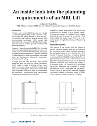
  • 1. An inside look into the planning requirements of an MRL Lift by Samson Rajan Babu IAEE Affiliate member, CIBSE Senior Vertical Transportation Engineer, Burt Hill - Dubai Introduction Unless the ‘special requirements’ of a MRL lift are “Machine room less” (MRL) lift concept has brought understood and allowed for in a building design, in a great design flexibility for the architects. MRL one may not receive a lift installation that is reliable lift concept has greatly helped in space savings, and safe: to use, to rescue and to maintain. This construction cost savings, energy savings and article addresses unique issues that need to be environmental friendliness. MRL concept has contemplated during building design, while planning contributed in the development of modern technology/ a MRL lift. products such as compact gearless machines and General Arrangement slim control panels. The majority of the modern MRL lifts consist of However, it should be noted that a MRL lift is a “special kid” requiring special attention and environment. For traction machines, placed within the lift shaft and a MRL lift to perform as efficiently, safely, reliably as an emergency control panel, preferably placed at a regular lift with machine room, it requires additional the top landing, adjacent to the landing door. The considerations from various professional disciplines variable frequency controller, emergency battery such as: Architecture, structural, mechanical, rescue controllers and additional group controller are electrical and life safety. placed within the head room space. Recent trends allow the emergency control panels and other control A single, low rise MRL lift project with minimal interaction with the ‘authority having jurisdiction’ panels to be located away from the top landing, in (AHJ) might be easy to execute without much a dedicated closet. The closet could be positioned hassle. However, a large scale, high profile project up to 5mtrs. away from the top landing or it could with intense participation and scrutiny of the AHJ be positioned up to 1 floor below the top landing. must be planned carefully in order to accommodate Traction machines are compact, low speed, gearless all interfacing requirements and performance ‘permanent magnet synchronous motor’ (PMSM) requirements mandated by such project. driven machines usually arranged in 2:1 roping. (b) Emergency control panel built inside (a) Emergency control panel beside the entrance at top floor the hall call station at top floor Fig1: General arrangement of emergency control panel for MRL lifts . Page 52 - ELEVATION - i64 www.elevationdirectory.com
  • 2. An inside look into the planning requirements of an MRL Lift Range of application geographical locations (such as the Middle East), where high temperatures and water condensation MRL lifts are commonly available up to 1600kgs is a problem. Further more, cooling and ventilating capacity and up to 1.75mps speeds. Greater capacities the head room space is a must when technicians are possible but with appropriate reduction in speed are required to spend a long time inside the lift shaft (for example: 2500kgs with 1.0mps speed). They trouble shooting the lifts. are used in all service conditions (i.e. passenger/ service/hospital/freight). MRL lifts support both wide This calls for ducted cooling in to the head room space and deep car configurations with center opening or along with humidity control. While the mechanical side opening doors. MRL lifts can be provided in engineer designs the cooling requirements and single entrance and double entrance configurations. cooling duct sizes (based on the heat rejection data from the lift supplier), the location of this duct Emergency control panels opening must be approved by the lift manufacturer Predominantly, these are slim type panels preferably so as not to clash with other lift equipment. located adjacent to the landing door at the top Further, it is recommended to have temperature landing and are used only for rescuing/trouble- sensors within the head room space to stop the lift, shooting purposes. These controllers can be a should there be an ‘overheating’ condition detected separate panel or can be built-in to the rear side of in the head room space. hall call stations at top floor. (Fig.1). Temperature and Humidity control at lift lobby Fig.(2) shows an emergency control panel built into the rear side of a hall call station. It may be Ideally, the emergency control panel is placed noted here that the hall call station at the top floor adjacent to the top floor landing. This is acceptable is considerably ‘taller’ than the hall stations at other assuming there is enough air-conditioning at the floors in order to accommodate additional control top floor lobby in order to maintain the temperature buttons and indicators. This often mandates using range and humidity conditions. In case there is no different types of hall call stations used on a single lift air-conditioning available at the top floor lobby, in group installation. The hall call stations at the top floor hot and humid climates, due to excessive heat and may not match the hall call stations at the other floors. water condensation, the controller could malfunction; electronic components could fail. Maintenance activities at the top floor Devices for emergency operations Since the entire machinery is located at the top of the lift shaft and the emergency control panel is located To carry out emergency rescue operations from the at the top floor, any rescue, maintenance or trouble- emergency control panel, the majority of the MRL shooting operation must be performed from the suppliers provide display devices to give indication top floor level. Depending on the situation, service of direction of movement and the car reaching technicians may require access to the top floor and unlocking zone such as directional arrows, LED door may be required to remain there for extended hours. zone indicators. Other manufacturers provide ‘rear This must be considered while planning penthouses vision panels’ (instead of directional arrows) to catch or executive offices at the top floors as it could an actual glimpse of the machinery/rope movement. become a considerable disturbance to the high- Such vision panels would be useful only if the profile occupants. emergency control panel is located within the lift Temperature and Humidity control at head room shaft frame. It is critical that this vision panel exactly space aligns with the moving equipment inside the lift shaft. If the control panel is not aligned or if it is moved Even though MRL lifts come with latest compact away from the lift shaft, then the ability to watch PMSM gearless machines, the temperature and the machinery/rope movement is lost. Under such humidity requirements have not changed from that circumstances, without directional arrows, it may be of lifts with machine room. Now that we have even necessary to install a CCTV camera to display rope more cramped space and the busy machine/drive movement at the emergency control panel. continuously releasing heat, the small head room space could heat up quickly and there should be Note on emergency control panels built-in to hall an engineered way to cool the head room space call stations and maintain the humidity within acceptable limits. Fig. (2) shows an emergency control panel built-in This may not be a problem for MRL lifts installed at to the hall call station. When 2 or more lifts are in locations with colder climates. a common shaft, often a combined hall call station However, this is very essential for hot and humid is used. Under such circumstances, the equipment Page 54 - ELEVATION - i64 www.elevationdirectory.com
  • 3. An inside look into the planning requirements of an MRL Lift Figure 2: Emergency controls built-inside hall call station layout should be carefully organised so that the rope To mitigate this risk, ‘inching’ method (i.e. opening movement of ‘each lift’ in the group is visible through the brake for a max of 23 seconds) is recommended the vision panels on the combined hall call station. If during rescue. However, should there be trouble not, additional hall call stations may be necessary in with the brake movement (mechanical or electrical) order to achieve visibility of rope movement for each or should the brake fail to close in again or should the technician not be alert, it is even more likely that the lift in the common shaft. (Fig. 3) Alternatively, CCTV sheave might ‘free-wheel’ uncontrollably. When this cameras inside lift shaft and/or directional arrows on condition occurs, the car can reach an ‘over speed the controller shall be utilised to ascertain direction condition’ and the safety gear will be deployed. This of car movement. is a major event, which should be avoided in regular Self induced dynamic braking a.k.a. Rush-away rescue operations. (free wheel) protection In order to prevent the lift car from reaching an over In the absence of a gear box, there is less friction speed condition, ‘self induced dynamic braking’ feature is necessary with the motor of a gearless in a gearless machine and it can rotate freely with machine. With this feature, during overhauling the slightest torque. When the brakes are opened, conditions, the motor develops a torque opposite depending on the heavier side, the machine sheave to the direction of rotation of the motor, which tends to ‘free-wheel’ and the lift car could reach an helps in reducing the free-wheel speed. This goes over speed condition. With large capacity lifts, the on continuously until the speed (and the dynamic counterweight and the car weight are so large that braking torque) is reduced to a safe level for the car controlling their movement manually is a difficult task. to hit the buffers in the pit. (a) (b) Fig 3: Configurations (a) would require two separate hall call stations to view rope movement through vision panel. It will be possible to view both lifts’ rope movement through a combined hall call station with configuration (b). Page 56 - ELEVATION - i64 www.elevationdirectory.com
  • 4. An inside look into the planning requirements of an MRL Lift Half-thick RCC front wall Maintenance access panel fully Maintenance access panel recessed into front wall affects fire partially recessed into front wall rating of hoistway/entrance preserves fire rating of hoistway/entrance Fig 4: Arrangement of emergency control panel within lift shaft frame. Fire rating integrity at top floor Fire rated lift shafts with fire rated entrances require extensive planning with respect to installing the landing door frames and fire sealing the entrance. However, when the lift controller is placed adjacent to landing door at top floor (within the front wall), in order to maintain the fire rating integrity of that floor, the emergency control panel must be ‘fire rating certified’ (such as UL UK, CSA) and the complete entrance (together with door jamb and the emergency control panel) must be fire sealed using methods authorised by a fire protection specialist. Alternatively a half-thick fire rated front wall can be built behind the controller, while the controller partially projects from the front wall (Fig. 4). Otherwise, the controller should be moved out of the fire rated lift shaft frame; this could cause inability to watch the rope movement and solutions as described above should be adopted. Space for additional controllers In addition to the lift controller, there are other control panels such as: the VF drive, emergency battery drive, group controller (for 3 and more lift groups), which also need space and they must be located somewhere on the building plan. Many manufacturers install these panels inside the lift shaft in the head room area (Fig. 5). Temperature and humidity control in the head room area is critical Figure 5: Additional control panels inside head room space: in order to provide habitable surroundings for these control panel, braking resistor unit, automatic control panels. rescue device, battery bank. www.elevationdirectory.com i64 - ELEVATION - Page 57
  • 5. An inside look into the planning requirements of an MRL Lift Rescue operation from top floor lobby (with power) When the power supply is still available and if a lift car has stopped in between floors due to malfunction, rescue operation has to be carried out from ‘emergency Emergency control panel control panel’ at the top floor lobby. The lift car is in stainless steel finish. moved in ‘maintenance mode’ by pressing up/down until the car reaches floor. Door zone indicators, directional arrows and a beep should be provided on the ‘emergency control panel’ to indicate that the car has reached the door opening zone. Rescue operation from top floor lobby (without power) When there is a power failure and if a lift car has stopped in between floors, the rescue operation has to be carried out from ‘emergency control panel’ at the top floor. The electro-mechanical brakes on the Emergency traction machine must be opened either electrically control panel in or manually. custom made shape & finish. For releasing brakes electrically, stand-by power supply, such as batteries, must be provided to open the brakes. Battery power is required also for the ‘emergency control panel’ to power the door zone indicators, directional arrows and beep sounds. Batteries should be of ‘rechargeable type’ and the Fig. 6 Visual impact of controllers at top floor lobby. availability of stand-by power supply as well as the recharging circuit of batteries must be monitored 24x7 with suitable alarm signals to indicate any Visual impact of controllers at top floor trouble with ‘recharging’. When controllers are placed adjacent to the top Alternatively, the brakes can be opened mechanically landing door or on a main lobby, the aesthetics using a ‘Bowden cable’ connecting the release lever and finishes of the control panel enclosure must to the brakes. The Bowden cable is routed through be reviewed. There shall not be any screws or pulleys and its proper movement must be checked ventilation slots on the control panel visible at the regularly to ensure its proper operation. Location lobby. It shall only present a smooth continuous and anchorage for such pulleys must be finalised in surface just like a door jamb. The control panel door consultation with the supplier. handle and lock shall be discreetly designed. The Rescue operation from top floor lobby (balanced surface finish of the control panel (on all exposed loads) sides) shall be verified to be compatible with the During a rescue operation (with or without power), lobby finishes. For special projects, the controllers the brakes are opened and the car usually moves up can also be fabricated in special shapes to achieve or down depending on the load condition within the a homogeneous lobby elevation at the top floor (at car. However, there could be situations where the additional cost) (Fig. 6). car load and the counterweight are equal and there is no torque on the sheave to move the car. Under Noise level at top floor such conditions, the sheave may need external Traction machines inside the lift shaft create agitation to induce movement to the main sheave. considerable amount of audible noise when the External power supply is required from a stand-by brakes drop and release. The VFD drive (usually power source such as rechargeable batteries to placed within the head room space) also creates cause the agitation. In case the car does not move even after agitating the sheave, then technicians will audible motor noise. Also there is relay switching be required to reach into the lift shaft to move the car noise from the control panel at the lobby. The by external force (see ‘Access into head room space’ noise level of this equipment must be ascertained below). Usually, weights are added to the car top to especially for quiet applications such as clinics, cause load imbalance and to effect car movement. hospitals, schools, conference rooms and executive Sometimes mechanical rope pullers are used to offices. move the car. Page 58 - ELEVATION - i64 www.elevationdirectory.com
  • 6. An inside look into the planning requirements of an MRL Lift Access into the head room space especially for the head room space (this condition is very similar to pit partitions, which protect the Even though MRL lifts have the design provision operatives from the moving parts of the other lift, at to carry out rescuing from the top floor lobby, there the pit level). Such partitions also prevent movement are numerous occasions when technicians would of technicians from one lift shaft to the adjacent lift need access into the head room space. Such as balanced car, maintenance and trouble-shooting of shaft, which could be very unsafe. machines, VFD and other controllers inside the head However, if the horizontal distance of the edge of a room space. lift car roof is less than 500mm from moving part of Usually the car top is utilised as the access platform an adjacent lift, then a full height lift shaft partition to carry out maintenance/repair procedures inside shall be provided as per EN81-1. the head room space. However, if the car is far below Ascending car over speed protection (ACO) the head room space and if it cannot be moved, then exclusive access ladders and working platforms will The modern variable frequency controlled MRL lifts be required inside the head room space. Usually, come with gearless machines, which utilise electro- these are deployed / removed through the top floor magnetic brakes (acting on main sheave) to stop the entrance. car during emergency. These brakes also hold the sheave in position once the variable frequency drive However, if the car has stopped at the top floor due to has stopped the motor. The EN81-1 code requires a malfunction and if it cannot be moved, alternative that any lift car should be protected against over access doors into the head room space are required. speeding in ‘upward’ direction too. Separate means The MRL lift design should incorporate access for this ACO protection must be provided within the ladders and platforms that are easily deployed and lift package. removed to facilitate such work. Alternatively, the EN81-1 code allows the electro- Partitions at the head room space magnetic brakes on the gearless machine to be utilised for providing ACO protection: provided there When two or more MRL lifts are installed within a is built-in redundancy and when correct operation common shaft, the technicians may be required to is monitored. It must be ensured that there are perform rescuing or trouble shooting works on one dual disc brakes on the traction machine with 100% lift in the head room space while the other is still in mechanical redundancy (Fig. 7). If not, external working condition. braking devices such as rope brake or sheave brake In order to protect technicians working inside the head or spring loaded guide rail brakes or a bi-directional room space, lift shaft partitions are recommended safety gear will be required. (a) (b) (c) (d) (e) (f) Fig 7: (a) Gearless machine with dual electro-magnetic brakes (b) Rope brake (c) Rope brake installed on a geared traction machine (d) Sheave brake (e) Rail brake (f) Bi-directional car safety gear. Page 60 - ELEVATION - i64 www.elevationdirectory.com
  • 7. An inside look into the planning requirements of an MRL Lift Bi-directional over speed governors for ACO In order to detect an ‘ascending over speed condition’, a bi-directional over speed governor or a similar device will be required. This type of governor detects over speeding in downward as well as upward direction. It must be ensured that the MRL lift is provided with ‘bidirectional governor’ or other means to ‘detect over speed in upward direction’. For the ‘downward over speed’ condition, the governor activates the progressive safety gear mechanism, while the ‘upward over speed condition’, the governor only generates a signal to operate any of the disc brake / rope brake / spring loaded guide Fig 8: Detector mechanism for unintended car movement. rail brake. Sometimes, the disconnect switches are located Unintended car movement protection (UCM) above the false ceiling level of lift lobby (Fig. 9). This is acceptable provided there is quick and easy As per EN81-1, any lift car should be protected means to access the switches. Often, it is proposed against ‘unintended car movement, when the doors to install the disconnect switches inside the head are not closed’. Separate means for this UCM room space. This may present a problem in case protection must be provided within the lift package. the car has stopped at the top floor level due to a Alternatively, the EN81-1 code allows disc brakes malfunction. on the gearless machine to be utilised for providing UCM protection; provided there is built-in redundancy and when correct operation is monitored. It must be ensured that there are dual disc brakes on the traction machine with 100% mechanical redundancy. If not, external braking devices such as rope brake or sheave brake will be required. Rope movement detector for UCM In order to detect ‘unintended car movement’, a standalone rope movement detector with a dedicated controller will be required. Usually, it is a roller in pressure contact against one of the main rope. (Fig. 8) When the main rope moves, the contact roller also moves. This information is verified by the dedicated controller against the door open or close condition. When there is abnormal rope movement (other than normal rope Fig. 9: Disconnect switches & interface modules stretch) (typically more than 150mm) when the doors located above gypsum ceiling level at the top floor. are open, the controller activates the safety brake and also removes the main power supply. It must be Communication devices within head room space ensured that the MRL lift is provided with this rope For rescuing and trouble-shooting purposes, suitable movement detector and control mechanism. communication devices (such as an intercom) Disconnect switches should be provided within the head room space. The 3-phase and 1-phase disconnect switches for This will enable proper communication between the the MRL lifts should be located outside the lift technicians inside the lift shaft and the passengers shaft in order to carry out rescue/maintenance trapped inside or another technician inside the car. tasks. The switches should be located very close Fire and Life safety related issues to the lift shaft and should be easily reachable. If architecturally clean lobbies are required at the top On a large, specialised project involving extensive floor, the disconnect switches may require cabinets fire and life safety requirements, specialised with suitable surface finishes. services such as lift shaft pressurization and lift shaft Page 62 - ELEVATION - i64 www.elevationdirectory.com
  • 8. An inside look into the planning requirements of an MRL Lift ventilation are required (these are not related to the ‘ducted air-conditioning’ provided at the head room space for the machinery). These services require additional openings on the lift shaft wall at the head room level. While the mechanical engineer designs the pressurization/ventilation requirements and the duct sizes, the location of these duct openings must be approved by the lift manufacturer so as not to clash with other lift equipment (Fig. 10). It could be an easier task to provide such openings and related ducting works for MRL lifts, which travel the full height of a building. However, these tasks become complicated when a MRL lift does not travel the full height of the building up to the top floor. Interfacing enhanced features on MRL lifts Large and specialised lift projects often involve Fig. 10 Additional mechanical openings enhanced operational features, such as card reader at the head room space . access, CCTV monitoring, fire alarm interface, public announcement, background music, building Lift shaft structure provisions management system interface, video displays and The traction machine of a MRL lift could be supported EPABX telephone systems. Wiring from/to each of either on machine support beams or on car guide these features requires to be connected to/from the rails. The machine beams are usually anchored lift controller at the head room space. Often, there and/or embedded into the lift shaft walls. When are individual interface controllers from each of these supported on car guide rails, additional anchorages systems, which are traditionally placed in the machine on the lift shaft wall are required at the head room room. For example, a card reader system has input/ space. Due to the 2:1 roping employed with MRL output module and a LCD display system has an lifts, there is also a rope hitch beam anchored and/or encoder board. Without a machine room, the space embedded into the lift shaft wall. and location of such interface controllers must be Both the machine support beam and the rope hitch studied and suitable space provisions must be made beam impose considerable loads on the lift shaft wall. within the head room space, without clashing with the While a 200mm thick RCC lift shaft wall can support lift equipment. If there is no space available within the imposed loads, a non-RCC lift shaft (block work the head room space, the interface panels must be lift shaft) will require structurally sound lintel beams located at a different location and only the wiring to/ at the head room space to transfer these loads to the from the panels is routed into the head room space. main structure and to receive additional anchorages. (a) (b) Fig 11: (a) Shows fire-rated grouting required on beam support pockets. (b) Shows the concrete edge clearances for the beam anchors. Page 64 - ELEVATION - i64 www.elevationdirectory.com
  • 9. An inside look into the planning requirements of an MRL Lift In order to fasten the machine beam and rope hitch If the project’s demands are extremely high, then beam to the lift shaft wall, usually recessed pockets above issues should be analysed systematically with (approx. 150mm deep) are required on the lift shaft the MRL lift supplier and a suitable maintenance walls. Sometimes, instead of a recess, through and rescue management plan should be developed openings are requested on the lift shaft wall. When for critical situations. The building management there is a fire rated lift shaft, these through openings operatives should be well informed and regularly must be sealed later using fire rated grouts (Fig. 11). trained on such special procedures in order to ensure Mechanical anchors may also be used along with rapid passenger rescue and safe maintenance grouting. Here, the concrete edge distances should be operations on the MRL lift installation. maintained according to the anchor size. If the hoist Since MRL lift design inherently comes with the wall is less than 200mm thick, mechanical anchors challenges described above, the advice is to could present a problem with the edge clearances. heed to the recommendations and requests of It should also be noted that the lifting hooks are the manufacturer. Try to follow equipment layouts to be provided on the roof slab of lift shaft. Often, preferred by the manufacturer as much as possible. the quantity of required lifting hook is more than Try not to alter such layouts, which might negatively the standard machine room type. The location of affect the safety/rescue features of the original MRL load hooks should be coordinated to match with the design. After all, it is the responsibility of the building traction machine layout. design consultant and the lift supplier to reduce risks ‘as low as is reasonably practicable’. Last but not the least - the CE certification References: ‘CE marking’ of a lift is the visible symbol indicating that the lift and its safety components meet the BS EN 81-1:1998+A3:2009: Safety rules for the construction and installation of lifts - Part 1: Electric lifts. requirements of the European Lifts Directive. The Machine room less lift product literature from various lift ‘CE marking’ of each MRL design is based on a brands. representative (model) set of equipment and equipment Uncontrolled movement detector installation manual: layout (and all foreseeable design variations) as Atwell International, UK. detailed in the Technical Dossier submitted for the Rope brakes: Bode components, Germany. EC type examination of the model MRL lift. The Rope brake system: Thyssenkrupp Dongyang Elevator. Technical Dossier records the components and the Sheave jammer: Thyssenkrupp Northern Elevator. general arrangement, which guarantee trouble free EBRA20 Rail brake: Wittur Group. operation, rescue and maintenance, in full compliance Bi-directional car safety gears: Wittur Group. with the Lift Directive. However, if any of the model equipment or model layouts of the MRL lift is altered T. SAMSON RAJAN BABU (other than the Technical Dossier), then the ‘CE marking’ will not be valid anymore. The manufacturer DUBAI – U. A. E. is legally responsible to ensure that the actual MRL Professional Highlights: lift installation (including special alterations, if any) T. Samson Rajan Babu is a Graduate conforms to the Lifts Directive and for applying the ‘CE Mechanical Engineer with more marking’ on its products. The buyer should be made than 14years’ total work experience aware of this fact when a non-standard equipment in electro-mechanical equipment layout is proposed for a project for any reason. industry. He has 11 years’ working experience in elevator/ escalator group design, specification development, post- Final word of recommendation contract project management installation management & Much of the above observation fall in the ‘rescue project sales of Elevators & Escalators. and maintenance’ category. The concerns related to Current responsibilities include expert services on safe access and rescue need not necessarily cause elevator group planning, VT system design, specification panic but only need practical analysis and solutions writing, tender management, post-contract construction on case-to-case basis. There is no doubt that the management, project execution quality control exclusively MRL lift concept uses state-of-the art equipment for elevator & escalator systems. Responsible for interfacing with other trades (life safety, mechanical, and technology. However, the probability of facing electrical, plumbing, fire fighting, interiors, communication, complicated and/or risky rescue, maintenance, and AV displays and BMS systems). trouble-shooting situations should be evaluated for each project depending on the usage demand Previous editorial contributions to Elevator World and an active member of the Chartered Institution of Building conditions, type of users, importance factor, project Services Engineers (CIBSE) UK – Lifts Group and the status aspirations and the targeted level of user Council on Tall Buildings and Urban Habitat (CTBUH), USA. safety and comfort. Page 66 - ELEVATION - i64 www.elevationdirectory.com