Call Girls Delhi {Jodhpur} 9711199012 high profile service
Dc machines ppt
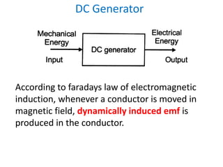
1. DC Generator
According to faradays law of electromagnetic
induction, whenever a conductor is moved in
magnetic field, dynamically induced emf is
produced in the conductor.
3. Poles
Made up of copper wire.
Current is passed through coils becomes
electromagnet and starts establishing magnetic field in
the machine and flux is distributed through the pole
Armature
Consists of armature core/
conductors/coils and
armature windings
It rotates under poles and
flux produced by field magnets
is cut by the armature conductors.
4. Commutator
Converts alternating emf to unidirectional emf
Brushes and Bearing
Collect the current from the commutator and
convey to external load
Principle of operation
7. E M F induced in a DC Generator
• let Ø be the flux per pole in webers
• let P be the number of poles
• let Z be the total number of conductors in the
armature
• All the Z conductors are not connected in
series. They are divided into groups and let A be
the number of parallel paths into which these
conductors are grouped.
8. • Each parallel path will have Z/A conductors in
series
• Let N be the speed of rotation in revolution
per minute (rpm)
• Consider one conductor on the periphery of
the armature. As this conductor makes one
complete revolution, it cuts PØ webers.
• As the speed is N rpm, the time taken for one
revolution is 60/N sec.
• Since the emf induced in the conductor is
equal to rate of change of flux cut.
9. • e α dØ/dt
= (PØ)/60/N
e = PNØ/60 volts
Since there are Z/A conductors in series in each
parallel path the emf induced
E g = (NPØ/60) (Z/A) volts
E g = (ØZN/60)(P/A) volts
• The armature conductors are generally connected
in two different ways, viz, lap winding and wave
winding. For lap wound armature A=P. In wave
wound machine, A = 2,always
10. Types of DC Generators
According to their methods of field
excitation, DC Generators are classified into
two types.
• Separately excited DC generator
• Self-excited DC generator
12. • I a = I L
• Ra = Resistance of the armature winding
• Terminal Voltage V = E g-Ia R a – V brush
• V brush = voltage drop at the contact of the brush
• Generally V brush is negelected because of very
low value
• Generally emf E g = V+ I a R a + V brush
• Electric power developed = E gIa
• Power delivered to load = VI a
15. • I a = I L = I se
• Generated emf E g = V+ I a R a + I se R se + V brush
Where,
V = terminal voltage in volts
Ia R a = voltage drop in the armature
Ia R se = voltage drop in the series field winding resistance
V brush = brush drop
• Terminal voltage V = E g-Ia R a - I a R se – V brush
• Power developed in the armature = E gIa
• Power delivered to load = VI a orV I L
17. • Terminal voltage V = E g-Ia R a
• Shunt field current Ish =V/ R sh
• Armature current I a = I L + I sh
• Power developed by armature = E gIa
• Power delivered to load = V I L
20. Long shunt compound generator
• Series field current I se = I a= I L + I sh
• Shunt field current Ish = V / R sh
• Generated emf E g = V + I a (R a + R sh) + V brush
• Terminal voltage V = E g – I a(R a+ R sh) – V brush
• Power developed in armature = E g I a
• Power delivered to load = V I L
22. Short shunt compound generator
• Series field current = I se =I L
• Load current = I L
• Armature current I a= I sh + I se
• Generated emf E g = V + I a R a + I se R se + V brush
• Voltage across shunt field winding = Ish R sh
• I sh R sh = E g – I a R a– V brush
= V + I a R a + I se R se + V brush – I a R a–V brush
= V + I se R se
23. Applications of DC Generators
• Shunt generators are used for supplying nearly
constant loads. They are used for battery
charging, for supplying the fields of synchronous
machines and separately excited DC machines
• Since the output voltage of a series generator
increases with load, series generators are ideal
for use as boosters for adding voltage to the
transmission line and to compensate for the line
drop.
• Compound generators maintain better voltage
regulation and hence find use where constancy of
voltage is required.
25. Principle of operation of DC Motor
• Whenever a current carrying conductor is placed in
magnetic field, the conductor experiences a force
tending to move it. (Lorentz force)
26. The direction of motion of conductor is given
by Fleming’s Left hand rule.
27. The magnitude of the force experienced by the
conductor is given by
F= BIL Newtons
Where,
B = magnitude of flux density in Wb/m2
I = current in amperes
L = length of the conductor in meters
28. Back EMF (or) Counter EMF
• The conductors are cutting flux and that is
exactly what is required for generator action
to take place.
• This means that even when machine is
working as a motor, voltage are induced in the
conductors. This emf is called as back emf or
counter emf(Lenz law)
• E b =(ØZN/60)(P/A) volts
30. • The voltage equation of this motor is
V= E b + I a R a
• Form this equation, armature current
I a = (V- E b )/ R a
Where,
V – applied voltage
E b = back emf
I a = armature current
R a = armature current
V - E b = net voltage in the armature circuit
31. Importance of Back EMF
• When DC motor is operating on no load condition,
Therefore the back emf is equal to input voltage and
armature current is small/decreseas.
• When the DC motor is operating on loaded
condition, speed decreases and motor back emf also
decreases. Corresponding armature current
increases.
• When load on the motor decreased, the speed
increases, the back emf also increases causing
armature current to decreases.
Regulates armature current
32. Voltage equation of DC motor
V – input voltage E b – back emf
R a – armature resistance; I a – armature current
I sh – shunt field current;R sh– shut field resistance
33. Voltage equation of DC motor
Here, the current flowing in the armature is
given by
I a = ( V – E b )/ R a
Or
V = E b + I a R a
This equation is known as voltage equation of a
DC motor.
34. Types of DC motors
According to their methods of field excitation,
DC motors are classified into two types.
• Separately excited DC motors
• Self-excited DC motors
. Series motor
. Shunt motor
. Compound motor
* long shunt compound motor
* short shunt compound motor
36. Separately excited DC motor
Armature current I a = line current I L
Back emf E b = V - I a R a – V brush
V brush is very small and therefore it is neglected
38. DC Series Motor
• I a = I L = I se
• The voltage equation is given by
V = E b+ I a R a + I se R se + V brush
I a = I se
V = E b+ I a ( R a + R se ) + V brush
V brush is neglected and hence
V = E b+ I a (R a + R se )
• Ø α I a α I a
43. Long shunt Compound Motor
• I L = I se + I sh
• I se = I a
• I L = I a + I sh
• I sh = V/ R sh
• Voltage equation is given by
V = E b+I a R a + I se R se + V brush
Where I a = I se
V = E b+ I a ( R a + R se ) + V brush
45. Short Shunt Compound Motor
• I L = I se
• I L = I a + I sh
• I L = I se = I a + I sh
• V = E b+Ia R a + Ise R se + V brush
• I se = I L
• V = E b+Ia R a + IL R se + V brush
• Voltage drop across the shunt field winding is = V
- I L = I se
• Vsh = E b+Ia R a + V brush
• I sh = V - IL R se / R sh
48. Torque Equation of a DC Motor
• Torque is nothing but turning or twisting force
about an axis
• Torque is measured by the product of force
and radius at which the force acts.
49. • The angular velocity of the wheel is
ω= (2ΠN)/60 rad/sec
Torque T = F × r (N-m)
Workdone per revolution = F × distance moved
= F × 2 Π r joules
Power developed P = workdone / time
= (F × 2 Π r)/time for 1 rev
= (F × 2 Π r)/(60/N)
(rpm = 60 ; rps = 60/N ; time for 1 rev = 60/N
P = (F × r) (2ΠN)/60
P = T ω watts
Where T = torque in N-m , ω = angular speed in rad/sec
50. • The gross mechanical power developed in the
armature is E b I a
• Then power in armature = armature torque × ω
E b Ia = Ta × (2ΠN)60
E b = PØZN/60A
PØZN/(60A) I a = Ta × (2ΠN)60
Ta = (Ø I a PZ)/ 2ΠA
Ta = (0.159Ø I a )(PZ/A) N-M
The above equation is torque equation of a DC motor.
Torque is proportional to the product of the armature
current and the flux
51. Speed control of DC shunt motor
For a Dc motor, the speed equation is obtained as follows
E b = V - I a R a
E b = PØZN/60A
V - I a R a = PØZN/60A
N = (V - I a R a )60A/ PØZ
Since for a given machine , Z,A and P are constants
N = K(V - I a R a )/Ø
Where K is a constant.
Speed equation becomes N α E b /Ø
Hence speed of the motor is directly proportional to back emf
and inversely proportional to flux. By varying flux and
voltage, the motor speed can be changed.
54. Speed control of DC series motor
1. Variable resistance in series with motor
55. 2. Flux control method
Field diverter Armature diverter
Tapped field control
56. For DC Shunt motor torque is directly proportional to
the armature current. For Dc series motor, the series field
current is equal to the armature current Ia
φ α Ia
HenceT α Ia α I2
a
For DC series motor, the torque is directly proportional to the
square of the armature current. The speed and torque
equations are mainly used for analyzing the various
characteristics of DC motors.
57. Applications of DC Motors
• DC shunt motor are used where speed has to maintain
nearly constant with load and where a high starting
torque is not required. Thus shunt motors may be used
for driving centrifugal pumps and light machine tools,
wood working machines, lathe etc.,
• Series motors are used where the load is directly
attached to the shaft or through a gear arrangements
and where there is no danger of load being “thrown
off”. Series motors are ideal for use in electric trains,
where the self-weight of the train acts as load and for
cranes, hoists, fans, blowers,converyers,lifts etc. where
starting torque requirement is high.
58. Applications of DC Motors
• Compound motors are used for driving heavy
machine tools for intermittent loads shears,
punching machines etc.,
69. Cooling arrangement in Transformers
• The various methods of cooling employed in a
transformer are
1. Oil immersed natural cooled transformers
2. Oil immersed forced air cooled transformers
3. Oil immersed water cooled transformers
4. Oil immersed forced oil cooled transformers
5. Air blast transformers
70.
71. EMF Equation of a Transformer
• N1 – Number of primary turns
• N2 – Number of secondary turns
72.
73.
74. We know that T= 1/f, where f is the frequency in Hz
Average rate of change of flux = φm/(1/4f) wb/seconds
If we assume single turn coil, then according to Faradays
law of electromagnetic induction, the average value of
emf induced/turn = 4 f φm volt
Form factor = RMS Value/ Average Value
= 1.11 (since φm is sinusoidal)
RMS value = Form Factor × Average Value
RMS Value of emf induced/turn = (1.11)×(4 f φm )
= 4.44 f φm volts
75. RMS value of emf induced in the entire
primary winding E1 = 4.44 f φm × N1
E1 = 4.44 f Bm A × N1 Volts
Similarly RMS value of emf induced in the
secondary E2 = 4.44 f Bm A × N2 Volts
76. Transformation Ratio (K)
For an ideal transformer
V1 = E1 ; V1 = E2;
V1I1 = V2I2
V2/V1 = I1/I2; E2/E1 = I1/I2
From transformer emf induced equation
E2/E1 = N1/N2
We have E2/E1 = N1/N2 = I1/I2= K
Where K is the transformation ratio.
If N2>N1 i.e. K>1, then transformer is a step up transformer.
If N2<N1 i.e. K<1, then transformer is a step down transformer
Voltage ratio = E2/E1 = K
Current ratio = I2/I1= 1/K
77. Ideal Transformer
The ideal transformer has the following
properties
• No winding resistance. i.e., purely inductive.
• No magnetic leakage flux.
• No I2 R loss i.e., no copper loss.
• No core loss.
78. Ideal Transformer
An ideal transformer consists of purely inductive
coil(winding) and loss free core. Windings are
wound on a core. It is shown in figure.
81. Rating of a Transformer
• Voltage rating
• Current rating
• Power rating
Why transformer rating in kVA?
82. Applications of Transformer
• Used in transmission and distribution
• Used as an instrument transformer for
measuring current (C.T) and measuring
voltage (P.T)
• Used as a step down and step up transformer
to get reduced or increased output voltage
• Radio and TV circuits, telephone circuits,
control and instrumentation circuits
• Furnaces and welding transformer
83. Single phase induction motor
These motors used in
• Homes
• Offices
• Shops
• Factories
They provide motive power for
• Fans
• Washing machines
• Hand tools like drillers, record player, refrigerator,
juice makers etc
84. Single phase induction motor
The single phase induction motor are simple
in construction. The main disadvantage of
these motors are
• Lack of starting torque
• Reduced power factor
• Low efficiency
87. Starting of single phase induction motor
• From the principle of operation, the single
phase induction motor has no self starting
torque. This can be explained in two ways
1. Two field (or) double field revolving theory
2. Cross field theory.
89. Double field revolving theory
Resultant flux would be 2× (φm/2)sinθ = φmsinθ
The resultant flux now is zero
90. Double field revolving theory
After half cycle, fluxes a and b will have resultant
of -2×(φm/2)= -φm
91. Double field revolving theory
After three quarters of cycle, again the resultant
is zero as shown.
92. Double field revolving theory
So the flux variation is φm , 0, -φm , 0. this flux
variation with respect to θ is plotted which is
shown below
93. Double field revolving theory
The slip of the rotor with respect to the forward
rotating flux is given by
S f = (Ns – N)/ Ns
The slip of the rotor with respect to the backward
rotating flux is given by
S b = (Ns – (-N))/ Ns
= 1 + (N/ Ns)
= 1 + 1-s
= 2-s
94. Double field revolving theory
Due to two more fluxes tow more torques
forward and backward torques and are
oppositely directed so that the net torque is
equal to their differences as shown
95. Operation of single phase induction motor
Due to the transformer action, currents are
induced in the rotor conductors. The direction
of the current is to oppose the stator mmf.
97. Types of single phase induction motor
The single phase induction motors can be
classified according to the phase difference
produced between the currents in the main
and auxiliary windings.
1. Split- phase motors
2. Capacitor-start motors
3. Capacitor-run motors
4. Capacitor-start and –run motors
5. Shaded-pole motors
100. Split phase induction motor
Applications:
It is mainly used for loads that require low and
medium torque. The applications are
• Fans
• Blowers
• Centrifugal pumps
• Washing machines
101. Split phase induction motor
characteristics
• The percentage of rated starting torque is
100% to 250%
• The break down torque is upto 300%
• The power factor of this motor is 0.5 to 0.65
• The efficiency of the motor is 55% to 65%
• The power rating of this motor is in the range
of ½ to 1HP.
104. Capacitor start single phase induction motor
Applications:
It is mainly used for hard starting loads, such as
1. Compressors
2. Pumps
3. Conveyors
4. Refrigerators
5. Air conditioning equipments
6. Washing machines
105. Capacitor start single phase induction motor
characteristics
• The percentage of rated starting torque is
250% to 400%
• The breakdown torque is upto 350%
• Power factor of the motor is 0.5 to 0.65
• The power rating of the motor is 1/8 to 1HP
• The efficiency of the motor is 55% to 65%
108. Capacitor run single phase induction motor
The main advantages of these motors are
• High power factor at full load
• High full-load efficiency
• Increased pull-out torque
• Low full-load line current
It is mainly used in low noise applications such as
• Fans
• Blowers
• Centrifugal pumps
109. Capacitor run single phase induction motor
The characteristics of these motors are
112. Capacitor start capacitor run motor
The main advantages of these motors are
• High starting torque
• High efficiency
• High power factor
113. Capacitor start capacitor run motor
It is mainly used for low noise and high starting
torque applications such as
• Compressors
• Pumps
• Conveyors
• Refrigerators
118. Shaded pole motor
The main disadvantages of these motors are
• Low efficiency
• Low power factor
• Very Low starting torque
119. Shaded pole motor
The main applications of these motors are for
loads requiring low starting torque such as
• Fans
• Blowers
• Turn tables
• Hair driers
• Motion picture projectors