SlideShare a Scribd company logo
1 of 33
Download to read offline
Manual for Micro-hydro power Development
Chapter 5
-5- 1 -
Study on Rural Energy Supply with Utilization of Renewable Energy
in Rural Areas in the Republic of Indonesia
CHAPTER 5 DESIGN FOR CIVIL STRUCTURES
The main obstacle for a small-scale hydropower plant is the high development cost. In
this chapter, element technologies are described assuming the need to reduce the
construction cost of civil structures (no description is given for those which equally
apply to the design of an ordinary hydropower plant).
5.1 Intake weir
5.1.1 Basic types of intake weirs
There are a number of basic types of intake weirs as listed below.
(1) Concrete gravity dam
(2) Floating concrete dam
(3) Earth dam
(4) Rock-fill dam
(5) Wet masonry dam
(6) Gabion dam
(7) Concrete reinforced gabion dam
(8) Brushwood dam
(9) Wooden dam
(10) Wooden frame with gravel dam
Of the above, the basically flexible rock-fill dam and gabion dam, etc. are popularly
used in Southeast Asian countries because of such advantages as (i) little influence by
the conditions of the ground base and (ii) relatively easy repair when damaged.
However, they can be breached by flooding due to their structure and their application
should be preceded by careful examination of the importance of constructing such a
civil structure and the conditions of the downstream.
Wet masonry dam
Manual for Micro-hydro power Development
Chapter 5
-5- 2 -
Study on Rural Energy Supply with Utilization of Renewable Energy
in Rural Areas in the Republic of Indonesia
Table 5.1.1 Basic types of intake weirs for small-scale hydropower plant and application
conditions
Type Outline Drawing Application Conditions
Concrete
gravity dam
Concrete is used for the construction of the
entire body.
Foundations: in principle, bedrock
River conditions: not affected by the
gradient, discharge
or level of
sediment load
Intake conditions: good interception
performance and
intake efficiency
Floating
concrete dam
Lengthened infiltration path of the
foundations by means of cut-off, etc. to
improve the interception performance
Foundations: in principle, gravel
River conditions: not affected by the
gradient, discharge
or level of
sediment load
Intake conditions: good interception
performance and
intake efficiency
Earth dam Earth is used as the main material for the
body; the introduction of a riprap and core
wall may be necessary depending on the
situation.
Foundations: variable from earth to
bedrock
River conditions: gentle flow and
easy to deal with
flooding
Intake conditions: good intake
efficiency because
a high interception
performance is
possible with
careful work
Manual for Micro-hydro power Development
Chapter 5
-5- 3 -
Study on Rural Energy Supply with Utilization of Renewable Energy
in Rural Areas in the Republic of Indonesia
Type Outline Drawing Application Conditions
Rock-fill dam Gravel is used as the main material for the
body. The introduction of a core wall may be
necessary depending on the situation.
Foundations: various, from earth to
bedrock
River conditions: river where an
earth dam could be
washed away by
the normal
discharge
Intake conditions: limited to the
partial use of river
water due to the
low intake
efficiency
Wet masonry
dam
Filling of the spaces between gravel with
mortar, etc.
Foundations: various, from earth to
bedrock
River conditions: not affected by the
gradient, discharge
or level of
sediment load
Intake conditions: good interception
performance and
intake efficiency
Gabion dam Gravel is wrapped by a metal net to improve
the integrity.
Foundations: various, from earth to
bedrock
River conditions: river where a rock-
fill dam could be
washed away by
the normal
discharge
Intake conditions: limited to the
partial use of river
water due to the
low intake
efficiency
Concrete
reinforced
gabion dam
Reinforcement of the gabion surface with
concrete
Foundations: various, from earth to
bedrock
River conditions: river where the
metal net could be
damaged due to
strong flow
Intake conditions: applicable when a
high intake
efficiency is
required
Manual for Micro-hydro power Development
Chapter 5
-5- 4 -
Study on Rural Energy Supply with Utilization of Renewable Energy
in Rural Areas in the Republic of Indonesia
Type Outline Drawing Application Conditions
Brushwood
dam
Simple weir using locally produced tree
branches, etc.
Foundations: various, from earth to
gravel layer
River conditions: loss due to flooding
is assumed
Intake conditions: at a site with a low
intake volume or
intake from a
stream to
supplement the
droughty water
flow
Wooden dam Weir using wood Foundations: various, from earth to
bedrock
River conditions: relatively gentle
flow with a low
level of sediment
transport
Intake conditions: a certain level of
intake efficiency is
secured with a
surface coating,
etc.
Wooden frame
with gravel
dam
The inside of the wooden frame is filled with
gravel to increase the stability.
Foundations: various, from earth to
bedrock
River conditions: river at which a
rock-ddddfill dam
could be washed
away by the
normal discharge
Intake conditions: limited to the
partial use of river
water due to the
low intake
efficiency
5.1.2 Decision on weir height
As the weir volume is proportionate to the square of the height, it is important to decide
the weir height in view of its minimisation taking the following conditions into
consideration.
(1) Conditions restricting waterway elevation
Manual for Micro-hydro power Development
Chapter 5
-5- 5 -
Study on Rural Energy Supply with Utilization of Renewable Energy
in Rural Areas in the Republic of Indonesia
To decide the weir height, it is necessary to take the topographical and geological
conditions of the waterway route into consideration in addition to the conditions at the
weir construction site. Careful examination is particularly necessary at a site where the
waterway construction cost accounts for a large proportion of the total construction cost.
The weir height at a site where the waterway is constructed under an existing road is
often decided with reference to the elevation of such a road.
(2) Possibility of riverbed rise in downstream
As the weir height for a small-scale hydropower plant is generally low, there is concern
that its normal function could be disrupted by a rise of the riverbed in the downstream.
Accordingly, the future riverbed rise should be assumed to decide the weir height if the
planned site falls under any of the following cases.
1) Gently sloping river with a high level of transported sediment
2) Existence of not fully filled check dam, etc. in the downstream of the planned
intake weir
3) Existence of a collapsing site in the downstream with concern in regard to
continuous collapse in the future
4) Existence of a narrow section in the downstream which obstructs the flow of
sediment and/or driftwood
(3) Conditions to remove sediment from front of weir and settling basin by intake
method (Tyrolean intake and side intake)
Under normal circumstances, the weir height should be planned to exceed the calculated
value by the following method to ensure the smooth removal of sediment from the front
of the weir and the settling basin.
1) Side intake
In the case of side intake, the following Case (a) or Case (b), which ever is the
higher, is adopted.
a. Weir height (D1) determined in relation to the bed elevation of the scour gate
of the intake weir
D1 = d1 + hi
Manual for Micro-hydro power Development
Chapter 5
-5- 6 -
Study on Rural Energy Supply with Utilization of Renewable Energy
in Rural Areas in the Republic of Indonesia
b. Weir height (D2) determined by the bed gradient of the settling basin
D2 = d2 + hi+ L (ic – ir)
Where,
d1 : height from the bed of the scour gate to the bed of the inlet (usually 0.5 – 1.0
m)
d2 : difference between the bed of the scour gate of the settling basin and the
riverbed at the same location (usually around 0.5 m)
hi : water depth of the inlet (usually determined to make the inflow velocity
approximately 0.5 – 1.0 m/s)
L : length of the settling basin (see Chapter 5-5.3 and Fig.5.3.1)
ic : inclination of the settling basin bed (usually around 1/20 – 1/30)
ir : present inclination of the river
Fig.5.1.1 Sectional view of side intake and weir
Inlet L
ic
ir
d2
d1
hi
Manual for Micro-hydro power Development
Chapter 5
-5- 7 -
Study on Rural Energy Supply with Utilization of Renewable Energy
in Rural Areas in the Republic of Indonesia
2) Tyrolean intake
A Tyrolean intake where water is taken from the bottom assumes that the front of
the weir is filled with sediment and, therefore, Case D2 determines the weir height
for side intake.
D2 = d2 + hi + L (ic – ir)
Fig.5.1.2 Sectional view of Tyrolean intake and weir
(4) Influence on electric energy generated
At a site where the usable head is small or where it is planned to secure the necessary
head by a weir, the weir height significantly influences the level of generated electric
energy. Accordingly, it is necessary to determine the weir height at such a site by
comparing the expected changes of both the construction cost and the generated electric
energy because of different weir heights.
(5) Influence of back water
When roads, residential land, farmland and bridges, etc. exist in a lower elevation area
in the upstream of a planned intake weir site, it is necessary to determine the weir height
to prevent flooding due to back water. Particularly at a site with a high weir height, the
degree of influence on the above features must be checked by means of back water
calculation or other methods.
Inlet L
ic
ir
d2
D2 hi
Manual for Micro-hydro power Development
Chapter 5
-5- 8 -
Study on Rural Energy Supply with Utilization of Renewable Energy
in Rural Areas in the Republic of Indonesia
5.2 Intake
5.2.1 Intake method
Apart from the ordinary side intake method, there are several types of simple intake
methods which aim at reducing the weir height and omitting the intake gate (hereinafter
referred to as the Tyrolean intake method) for a hydropower plant. Two typical
examples are listed below.
• Bar screen type
• Bar-less type
The details of these two types are shown in Table 5.2.1.
Manual
for
Micro-hydro
power
Development
Chapter
5
Study
on
Rural
Energy
Supply
with
Utilization
of
Renewable
Energy
in
Rural
Areas
in
the
Republic
of
Indonesia
Table
5.2.1
Typical
examples
of
Tyrolean
intake
methods
Intake
Method
Outline
Drawing
Characteristics
Advantages
and
Problems
Found
by
Actual
Performance
Survey
Bar
screen
type
•
If
a
screen
is
installed
to
cover
most
of
the
river
channel,
it
is
highly
resistant
to
riverbed
fluctuations.
A
sufficiently
wide
intake
width
enables
100%
intake
of
river
water.
As
overflow
may
occur
due
to
fallen
leaves,
etc.
gathering
on
the
screen
surface,
the
screen
width
should
have
a
sufficient
margin.
The
sedimentation
capacity
of
the
weir
to
deal
with
sediment
inflow
should
also
be
analysed.
•
This
type
is
popularly
used
and
the
intake
rate
is
said
to
be
generally
0.1
–
0.3
m
3
/s
per
unit
width
based
on
a
bar
installation
angle
of
up
to
30°,
an
inter-bar
space
of
20
–
30
mm
and
a
bar
length
of
approximately
1
m.
<
Advantages
>
•
A
scour
gate
of
intake
weir
can
be
omitted.
•
A
compact
intake
facility
is
suitable
for
a
narrow
or
rapid
river.
•
Stable
intake
is
possible
despite
a
change
of
the
riverbed
upstream.
<
Problems
>
•
At
the
time
of
flooding
or
water
discharge,
sediment
and
litter
flow
into
the
waterway.
•
A
screen
which
is
clogged
with
gravel,
etc.
requires
much
labour
for
its
removal.
Bar-less
type
•
The
running
water
usually
overflows
the
fixed
weir
top
and
is
guided
into
the
settling
basin
via
an
intake
channel
placed
across
the
river
channel
and
along
the
endsill
(deflector).
With
an
increase
of
the
river
discharge,
the
running
water
overflows
the
endsill
and
eventually
becomes
a
rapid
flow
to
fly
over
the
endsill,
making
intake
impossible
at
the
time
of
flooding.
However,
sediment
deposited
in
the
intake
channel
is
washed
away
towards
the
downstream
of
the
endsill,
making
maintenance
of
the
intake
channel
easier.
While
the
sectional
form
of
this
type
is
similar
to
that
of
the
bar
screen
type,
the
absence
of
a
screen
means
a
reduction
of
the
maintenance
cost
and
labour
related
to
the
screen.
<
Advantage)
•
A
compact
intake
facility
is
suitable
for
a
narrow
or
rapid
river.
•
Stable
intake
is
possible
despite
a
change
of
the
riverbed
upstream.
•
Sediment
and
litter
are
discharged
naturally
at
the
time
of
flooding.
<
Problem
>
•
Plenty
of
sediment
and
litter
inflow
to
the
waterway.
•
Frequently
of
scouring
of
settling
basin
is
required.
-5- 9 -
Manual for Micro-hydro power Development
Chapter 5
-5- 10-
Study on Rural Energy Supply with Utilization of Renewable Energy
in Rural Areas in the Republic of Indonesia
5.2.2 Important points for intake design
For the design of the intake for a small-scale hydropower plant, it is necessary to
examine the possible omission of an intake gate and others in order to achieve cost
reduction.
In the case of a small-scale hydropower plant, the headrace tends to be an open channel,
a covered channel or a closed conduit. When this type of headrace is employed, it is
essential to avoid a water inflow volume which considerably exceeds the design intake
volume as it will directly lead to the destruction of the headrace.
Meanwhile, as automatic gate control for a small-scale hydropower plant results in a
cost increase, manual control is opted for. In the case of the intake facility for a small-
scale hydropower plant being constructed in a remote mountain area, a swift response to
flooding is difficult. The following method is, therefore, proposed to control the inflow
at the time of flooding without the use of a gate, etc.
(1) Principle
This method intends the design of an intake which becomes an orifice with a rise of the
river water level due to flooding and is frequently used for a Tyrolean intake or for
small-scale hydropower plants in Indonesia.
The inflow volume in this case is calculated by the formula below.
H
Q f= Ai ×Cv × Ca × (2 ×g × H ) 0.5
Where,
Qf : inflow volume of submerged orifice (m3
/s)
Ai : area of intake (m2
) Ai=bi × (dh + hi) dh=0.10~0.15m
Flood Water Level
→
Water Level of Spillway
Normal Water Level
Bsp
hsp
Ai
hi
dh
dh
hi
bi
Manual for Micro-hydro power Development
Chapter 5
-5- 11-
Study on Rural Energy Supply with Utilization of Renewable Energy
in Rural Areas in the Republic of Indonesia
Cv : coefficient of velocity: Cv = 1/(1 + f)
f : coefficient of inflow loss (see next figure)
Bsp, hsp: refer to Chapter 5-5.3 Settling basin
Fig.5.2.1 Coefficient of inflow loss of various inlet form
Ca : coefficient of contraction (approximately 0.6; see the following formula)
where,
D, d: ratio between upstream flow and downstream flow of contracting flow
when, d << D, Ca = 0.582
H: water level difference between upstream and downstream of the orifice (m)
(2) Equipment outline
The important points for design are listed below.
1) It is necessary for the intake to have a closed tap instead of an open tap so that it
becomes a pressure intake when the river water level rises.
2) The intake should be placed at a right angle to the river flow direction where
possible so that the head of the approaching velocity at the time of flooding is
minimised.
3) As water inflow at the time of flooding exceeds the design intake volume, the
spillway capacity at the settling basin or starting point of the headrace should be
fairly large.
Angularity Haunch Rounded
Bellmouth Protruding
f = 0.1 (round)
- 0.2 (orthogon)
f = 0.5 f = 0.25
f = 0.05 – 0.01 f = 0.1
f = 0.5 + 0.3 cosθ
+ 0.2 cos2
θ
θ
Ca = 0.582 + (Merriman’s formula)
0.0418
1.1 + d/D
Manual for Micro-hydro power Development
Chapter 5
-5- 12-
Study on Rural Energy Supply with Utilization of Renewable Energy
in Rural Areas in the Republic of Indonesia
5.3 Settling basin
The settling basin must have not only a structure which is capable of settling and
removing sediment which is a size larger than the minimum size which could have an
adverse impact on the turbine, etc. but also a spillway to prevent excessive water inflow
into the headrace. The basic configuration of a settling basin is illustrated below.
Fig.5.3.1 Basic configuration of settling basin
[Refference]
In oblong section, uniform flow depth: ho1=H*×0.1/(SLs)0.5
H* : refer to {Ref.5-1}
SLs : slope of top end of the headrace
ho2={(α×Qd2
)/(g×B2
)}1/3
α=1.1
Qd= Design Discharge (m3
/s)
g=9.8
Conduit section
Widening section
Settling section
B
b
1.0
2.0
Dam
Spillway
Stoplog Flushing gate
Intake
Headrace
Bsp
hs
hsp+15cm
h0
10~15
cm
hi
ic=1/20~1/30
Intake
Stoplog
bi
Lc Lw Ls
L
Sediment Pit
Flushing gate
Manual for Micro-hydro power Development
Chapter 5
-5- 13-
Study on Rural Energy Supply with Utilization of Renewable Energy
in Rural Areas in the Republic of Indonesia
B:Width of Headrace (m)
if ho1<ho2, ho=ho1
if ho1≦ho2, ho=ho2
Each of these sections has the following function.
(1) Conduit section
Conduit section connects the intake with the settling basin. It is necessary that the
conduit section should be curtailing its length.
(2) Widening section:
This regulates water flow from the conduit channel to prevent the occurrence of
whirlpools and turbulent flow and reduces the flow velocity inside the settling basin to a
predetermined velocity.
(3) Settling section:
This section functions to settle sediment above a certain size and its required length (l)
is calculated by the following formula based on the relation between the settling speed,
flow velocity in the settling basin and water depth.
The length of the settling basin (Ls) is usually determined so as to incorporate a margin
to double the calculated length by the said formula.
Where,
l : minimum length of settling basin (m)
hs : water depth of settling basin (m) ( -see Fig.5.31)
U : marginal settling speed for sediment to be settled (m/s)
usually around 0.1 m/s for a target grain size of 0.5 – 1 mm.
V : mean flow velocity in settling basin (m/s)
usually around 0.3 m/s but up to 0.6 m/s is tolerated in the case where the
width of the settling basin is restricted.
V = Qd/(B×hs)
Qd: design discharge (m3
/s)
B : width of settling basin (m)
l ≥ ×hs L s= 2×l
V
U
Manual for Micro-hydro power Development
Chapter 5
-5- 14-
Study on Rural Energy Supply with Utilization of Renewable Energy
in Rural Areas in the Republic of Indonesia
(4) Sediment pit:
This is the area in which sediment is deposited.
(5) Spillway
Spillway drains the submerged inflow which flows from the intake. The sizes of
spillway will be decided by following equation.
Qf= C×Bsp×hsp1.5
→hsp={Qf /(C×Bcp)}1/1.5
Where,
Qf : inflow volume of submerged orifice (m3
/s, see Chapter 5-5.2.2 (1))
C : coefficient =1.80
hsp: water depth at the spillway (m, see Fig 5.3.1)
Bsp: width of the spillway (m, see Fig.5.3.1)
Manual for Micro-hydro power Development
Chapter 5
-5- 15-
Study on Rural Energy Supply with Utilization of Renewable Energy
in Rural Areas in the Republic of Indonesia
5.4 Headrace
5.4.1 Type and Basic Structure of Headrace
Because of the generally small amount of water conveyance, the headrace for a small-
scale hydropower plant basically adopts an exposed structure, such as an open channel
or a covered channel, etc. Some examples and their basic structures are given in Table
5.4.1 and Table 5.4.2 respectively.
Manual
for
Micro-hydro
power
Development
Chapter
5
Study
on
Rural
Energy
Supply
with
Utilization
of
Renewable
Energy
in
Rural
Areas
in
the
Republic
of
Indonesia
Table
5.4.1
Types
of
headraces
for
small-scale
hydropower
plants
Type
Outline
Drawing
Advantages
and
Problems
Typical
Structure
Open
channel
<
Advantages
>
•
Relatively
inexpensive
•
Easy
construction
<
Problems
>
•
Possible
inflow
of
sediment
from
the
slope
above
•
High
incursion
rate
of
fallen
leaves,
etc.
•
Simple
earth
channel
•
Lined
channel
(dry
or
wet
masonry
lining;
concrete
lining)
•
Fenced
channel
(made
of
wood,
concrete
or
copper)
•
Sheet-lined
channel
•
Half-tube
channel
(corrugated
piping,
etc.)
Closed
conduit
/
Covered
channel
<
Advantages
>
•
Generally
large
earth
work
volume
•
Low
incursion
rate
of
sediment
and
fallen
leaves,
etc.
into
the
channel
<
Problems
>
•
Less
easier
channel
inspection,
maintenance
work,
including
sediment
removal,
and
repair
•
Buried
tube
(Hume,
PVC
or
FRPM)
•
Box
culvert
•
Fenced
channel
with
cover
-5- 16 -
Manual for Micro-hydro power Development
Chapter 5
-5-17-
Study on Rural Energy Supply with Utilization of Renewable Energy
in Rural Areas in the Republic of Indonesia
Table 5.4.2 Basic structure of headraces for small-scale hydropower plants
Type Outline Diagram Advantages and Problems
Simple earth
channel
< Advantages >
• Easy construction
• Inexpensive
• Easy repair
< Problems >
• Possible scouring or collapse of the
walls
• Not applicable to highly permeable
ground
• Difficult to mechanise the sediment
removal work
Lined channel
(rock and
stone)
< Advantages >
• Relatively easy construction
• Can be constructed using only local
materials
• High resistance to side scouring
• Relatively easy repair
< Problems >
• Not applicable to highly permeable
ground
Wet masonry
channel
< Advantages >
• Local materials can be used
• Strong resistance to back scouring
• Can be constructed on relatively high
permeable ground.
• Easy construction at the curved
section due to the non-use of forms
< Problems >
• More expensive than a simple earth
channel or dry masonry channel
(rock/stone-lined channel)
• Relatively takes labour hours.
Concrete
channel
< Advantages >
• High degree of freedom for cross-
section design
< Problems >
• Difficult construction when the inner
diameter is small
• Relatively long construction period
n=0.030
n=0.025
Plastered : n=0.015
Non Plastered : n=0.020
n=0.015
Manual for Micro-hydro power Development
Chapter 5
-5-18-
Study on Rural Energy Supply with Utilization of Renewable Energy
in Rural Areas in the Republic of Indonesia
Type Outline Diagram Advantages and Problems
Wood fenced
channel
< Advantages >
• Less expensive than a concrete
channel
• Flexible to allow minor ground
deformation
< Problems >
• Limited use with earth foundations
• Unsuitable for a large cross-section
• Difficult to ensure perfect water-
tightness
• Liable to decay
Box culvert
channel
< Advantages >
• Easier construction than a Hume pipe
on a slope with a steep cross-
sectional gradient
• Relatively short construction period
and applicable to a small cross-
section when ready-made products
are used
• Rich variety of ready-made products
< Problems >
• Heavy weight and high
transportation cost when ready-made
products are used
• Long construction period when box
culverts are made on site
Hume pipe
channel
< Advantages >
• Easy construction on a gently sloping
site
• Relatively short construction period
• High resistance to external pressure
• Applicable to a small cross-section
• Elevated construction with a short
span is possible
< Problems >
• Heavy weight and high
transportation cost
n=0.015
n=0.015
n=0.015
Manual for Micro-hydro power Development
Chapter 5
-5-19-
Study on Rural Energy Supply with Utilization of Renewable Energy
in Rural Areas in the Republic of Indonesia
5.4.2 Determining the Cross Section and Longitudinal Slope
The size of cross section and slope should be determined in such a manner that the
required turbine discharge can be economically guided to the head tank. Generally, the
size of cross section is closely related to the slope. The slope of headrace should be
made gentler for reducing head loss (difference between water level at intake and at
head tank) but this causes a lower velocity and thus a lager cross section. On the
contrary, a steeper slope will create a higher velocity and smaller section but also a
lager head loss.
Generally, in the case of small-hydro scheme, the slope of headrace will be determined
as 1/500 – 1/1,500. However in the case of micro-hydro scheme, the slope will be
determined as 1/50 – 1/500, due to low skill on the survey of levelling and construction
by local contractor.
The cross section of headrace is determined by following method.
(1) Method of calculation
Qd= A ×R 2/3
×SL
1/2
/n
Qd : design discharge for headrace (m3
/s)
A : area of cross section (m2
)
R : R=A/P (m)
P : length of wet sides (m) refer to next figure.
SL : longitudinal slope of headrace (e.g. SL= 1/100=0.01)
n : coefficient of roughness (see Table 5.4.2)
For instance, in the case of rectangular cross section, width (B)=0.6m, water depth
(h)=0.5m, longitudinal slope (SL)=1/200=0.005, coefficient of roughness (n)=0.015.
A= B×h = 0.6 × 0.5 = 0.30 m2
P= B + 2 × h = 0.6 + 2 × 0.5 =1.60 m
R= A/P = 0.30/1.60 = 0.188 m
∴ Qd= A ×R 2/3
×SL
1/2
/n = 0.30 ×1.60 2/3
×0.005 1/2
/0.015 = 1.94 m3
/s
Water surface
: P
Manual for Micro-hydro power Development
Chapter 5
-5-20-
Study on Rural Energy Supply with Utilization of Renewable Energy
in Rural Areas in the Republic of Indonesia
(2) Simple method
In order to simplify the above method, following method for determining the cross
section is used in [Reference 5-1 Simple Method for Determining the Cross Section]
This reference will be used in determination of cross section in the following two
sectional forms.
Rectangular cross section Trapezoid cross section
H* should be calculated on each different slope. For instance, in the case of trapezoid
cross section, design discharge (Q)=0.5m3
/s, width (B)=0.8m, longitudinal slope
(SLA,B,C,D)=1/100, 1/50, 1/100, 1/200 which is the gentlest position of the headrace,
coefficient of roughness (n)=0.015.
Water depth (H*) is approximately 0.3m in Reference 5-1 Fig-4. Therefore actual water
depth (H) is
H = H* × 0.1 /(SL)0.5
HA,C = H* × 0.1 /(SLA,C)0.5
= 0.3×0.1/(0.01) 0.5
= 0.3
HB = H* × 0.1 /(SLB)0.5
= 0.3×0.1/(0.02) 0.5
= 0.21
HD = H* × 0.1 /(SLD)0.5
= 0.3×0.1/(0.005) 0.5
= 0.42
and height of the cross section of Slope A,C is 0.60m(0.3+0.2~0.3),
height of the cross section of Slope B is 0.55m(0.21+0.2~0.3),
height of the cross section of Slope D is 0.75m(0.42+0.2~0.3).
B=0.6 and 0.8m
1.0
m=0.5
B=0.6 and 0.8m
Slope A
Slope B
Slope C
Slope D
SLA = 1/100
SLB = 1/50
SLC = 1/100
SLD = 1/200
Manual for Micro-hydro power Development
Chapter 5
-5-21-
Study on Rural Energy Supply with Utilization of Renewable Energy
in Rural Areas in the Republic of Indonesia
5.5 Head Tank
5.5.1 Head tank capacity
(1) Function of headtank
The functions of headtank are roughly the following 2 items.
• Control difference of discharge in a penstock and a headrace cause of load
fluctuation.
• Finally remove litter (earth and sand, driftwood, etc.) in flowing water
(2) Definition of head tank capacity
The head tank capacity is defined the water depth from hc to h0 in the head tank length L
as shown in Fig.5.5.1.
Fig.5.5.1 Picture of headtank capacity
0.5
1.0
dsc
As
d
Bspw
hc
h0
h>1.0×d
S=1~2×d
1.0
20.0
B
L
1.0
2.0
30~50cm
b
B-b
Headrace
30~50cm
Ht
Spillway
Screen
SLe
h0=H*×0.1/(Sle)
0.5
H*:Refer to 'Reference 5-1'
hc={(α×Qd2
)/(g×B2
)}1/3
α=1.1 g=9.8
d=1.273×(Qd/Vopt)0.5
Vopt:Refer to 'Reference 5-2'
Vsc=As×dsc=B×L×dsc≧10sec×Qd
B,dsc:desided depend on site condition.
Manual for Micro-hydro power Development
Chapter 5
-5-22-
Study on Rural Energy Supply with Utilization of Renewable Energy
in Rural Areas in the Republic of Indonesia
Headtank capacity Vsc = As×dsc=B×L×dsc
where, As: area of headtank
B : width of headtank
L : length of headtank
dsc: water depth from uniform flow depth of a headrace when using
maximum discharge (h0) to critical depth from top of a dike for sand
trap in a headtank (hc)
[Reference]
In oblong section, uniform flow depth: ho=H*×0.1/(SLe)0.5
H* : refer to {Ref.5-1}
SLe : slope of tail end of the headrace
critical depth: hc={(α×Qd2
)/(g×B2
)}1/3
α: 1.1 g : 9.8
(3) Determine a headtank capacity
The headtank capacity should be determined in consideration of load control method
and discharge method as mentioned below.
a. In case only load is controlled
In the case where only controlled load (demand) fluctuation has been considered,
generally a dummy load governor is adopted. A dummy load governor is
composed of water-cooled heater or air-cooled heater, difference of electric power
between generated in powerhouse and actual load is made to absorb heater. The
discharge control is not performed.
The head tank capacity should be secured only to absorb the pulsation from
headrace that is about 10 times to 20 times of the design discharge (Qd).
A view showing a frame format of load controlled by a dummy load governor is
shown in Fig.5.5.2.
Fig.5.5.2 Pattern diagram of dummy load consumption
Generated power
Dummy load consumption
Time
Power demand
Electric
power
Water
discharge
Manual for Micro-hydro power Development
Chapter 5
-5-23-
Study on Rural Energy Supply with Utilization of Renewable Energy
in Rural Areas in the Republic of Indonesia
b. In case both load and discharge are controlled
In the case of controlled load and discharge, a mechanical governor or electrical
governor is used for load control. These governors have the function of controling
vane operation to optimal discharge when electrical load has changed. Generally a
mechanical governor is not sensitive to load change, and head tank capacity in this
case should be secured 120 times to 180 times of Qd.
On the other hand, an electrical governor is responsive to load change, therefore
head tank capacity is designed about 30 times to 60 times of Qd in many cases.
5.5.2 Important issues for head tank design
The design details for the head tank for a small-scale hydropower plant are basically the
same as those for a small to medium-scale hydropower plant and the particularly
important issues are discussed below.
(1) Covering water depth and installation height of penstock inlet
As the penstock diameter is generally small (usually 1.0 m or less) in the case of a
small-scale hydropower plant, it should be sufficient to secure a covering water depth
that is equal to or larger than the inner diameter of the penstock. However, in the case of
a channel where both the inner diameter and inclination of the penstock are as large as
illustrated below, the occurrence of inflow turbulence has been reported in the past.
Accordingly, the covering water depth must be decided with reference to the illustration
below when the inner diameter of the penstock exceeds 1.0 m.
Vertical angle
Swirly when Qmax
Manual for Micro-hydro power Development
Chapter 5
-5-24-
Study on Rural Energy Supply with Utilization of Renewable Energy
in Rural Areas in the Republic of Indonesia
h = d2
Where,
h : water depth from the centre of the inlet to the lowest water level of the head
tank = covering water depth (m)
d : inner diameter of the penstock (m)
• Covering Water Depth
The covering water depth at the penstock inlet must be above the following value
to prevent the occurrence of inflow turbulence.
d ≤ 1.0 m → h ≥ 1.0 d
d > 1.0 m → h ≥ d2
Where,
h : water depth from the centre of the inlet to the lowest water level of the head
tank = covering water depth (m)
d : inner diameter of the penstock (m)
• Installation height of penstock
There are many reports of cases where inappropriate operation has caused the
inflow of sediment into the penstock, damage the turbine and other equipment.
Accordingly, it is desirable for the inlet bottom of the penstock to be placed
slightly higher than the apron of the head tank (some 30 – 50 cm).
NWL
LWL
h
30~50cm
d
1~2d
Manual for Micro-hydro power Development
Chapter 5
-5-25-
Study on Rural Energy Supply with Utilization of Renewable Energy
in Rural Areas in the Republic of Indonesia
(2) Appropriate spacing of screen bars for turbine type, etc.
The spacing of the screen bars (effective screen mesh size) is roughly determined by the
gate valve diameter but must be finalised in consideration of the type and dimensions of
the turbine and the quantity as well as quality of the litter. The reference value of an
effective screen mesh size is shown below.
Effective screen mesh size (reference)
(3) Installation of vent pipe to complement head tank gate
When a head tank gate is installed instead of a gate valve for a power station, it is
necessary to install a vent pipe behind the head tank gate to prevent the rupture of the
penstock line.
In this case, the following empirical formula is proposed to determine the dimensions of
the vent pipe.
Where,
d : inner diameter of the vent pipe (m)
P : rated output of the turbine (kW)
L : total length of the vent pipe (m)
H : head (m)
200 400 600 800 1000
20
50
Gate Valve Diameter (mm)
Effective
Screen Mesh
Size (mm)
d = 0.0068 ( ) 0.273
P2
・L
H2
Manual for Micro-hydro power Development
Chapter 5
-5-26-
Study on Rural Energy Supply with Utilization of Renewable Energy
in Rural Areas in the Republic of Indonesia
Source: Sarkaria, G.S., “Quick Design of Air Vents for Power Intakes”, Proc. A.S.C.E.,
Vol. 85, No. PO.6, Dec., 1959
(4) Spillway at the headtank
Generally, the spillway will be installed at the head tank so that excessive quantity of
water is discharged to the river safely when the turbine is stopped.
The size of spillway is decided by following equation.
Qd=C×Bspw×hspw
1.5
→ hspw={Qd/(C×Bspw)}1/1.5
Qd : design discharge (m3
/s)
C : cofficient, usually C=1.8
Bspw : width of spillway (m , refer to Fig 5.1.1)
hspw : depth at the spillway (m)
Manual for Micro-hydro power Development
Chapter 5
-5-27-
Study on Rural Energy Supply with Utilization of Renewable Energy
in Rural Areas in the Republic of Indonesia
5.6 Penstock
5.6.1 Penstock material
At present, the main pipe materials for a penstock are steel piping, ductile iron piping
and FRPM (fibre reinforced plastic multi-unit) piping. In the case of a small-scale
hydropower plant, the use of hard vinyl chloride piping, Howell piping or spiral welded
piping can be considered because of the small diameter and relatively low internal
pressure. The characteristics of each pipe material are shown in “Table 5.6.1 – Penstock
pipe materials for small-scale hydropower plant”.
5.6.2 Calculation of steel pipe thickness
The minimum thickness of steel pipe of penstock is determined by following formula.
where, t0: minimum thickness of pipe
P: design water pressure i.e. hydrostatic pressure + water hammer
(kgf/cm2
) , in micro-hydro scheme P=1.1×hydrostatic pressure.
for instance, if the head (Hp, refer to following figure) from head tank to
turbine is 25m, P=2.5×1.1=2.75 kgf/cm2
.
d: inside diameter (cm)
θa: admissible stress (kgf/cm2
) SS400: 1300kgf/cm2
η: welding efficiency (0.85~0.9)
δt : margin (0.15cm in general)
5.6.3 Determining the Diameter of Penstock
Generally the diameter of penstock is determined by comparison between the cost of
penstock and head loss at penstock. However a simple method for determining the
diameter of penstock is indicated in [Reference 5-2 Simple Method for Determining the
Diameter of Penstock] .
The diameter of penstock will be determined from “Average angle of Penstock (Ap: see
following figure) “ and “Design Discharge (Qd)”.
t0 = + δt (cm)
P×d
2×θa×η
and t0=≧0.4cm or t0≧(d+80)/40 cm
Manual for Micro-hydro power Development
Chapter 5
-5-28-
Study on Rural Energy Supply with Utilization of Renewable Energy
in Rural Areas in the Republic of Indonesia
For instance, in the case of design discharge (Qd)=0.50m3
/s,length of penstock
(Lp)=60m, height from head tank to power house (Hp)=15m, average angle
(Ap)=15/60=0.25, the optimum velocity (Vopt) is determined as about 2.32 in
Reference 5-2. Therefore the diameter of penstock pipe (d) is
d = 1.273 × (Qd/Vopt)0.5
=1.273 × (0.5/2.32)0.5
= 0.59 m
Lp
Head Tank
Power House
Hp
Ap = Hp / Lp
Manual
for
Micro-hydro
power
Development
Chapter
5
Study
on
Rural
Energy
Supply
with
Utilization
of
Renewable
Energy
in
Rural
Areas
in
the
Republic
of
Indonesia
Table
5.6.1
Penstock
pipe
materials
for
small-scale
hydropower
plant
Resin
Pipe
Iron
Pipe
Hard
Vinyl
Chloride
Pipe
Howell
Pipe
FRP
Pipe
Steel
Pipe
Ductile
Iron
Pipe
Spiral
Welded
Pipe
Characteristics
•
Most
popular
material
for
a
pipeline
as
it
is
frequently
used
for
water
supply
and
sewer
lines
•
Effective
for
a
pipeline
with
a
small
discharge
•
Rich
variety
of
ready-made
irregular
pipes
•
Often
buried
due
to
weak
resistance
to
impact
and
large
coefficient
of
linear
expansion
•
Basically
resistant
to
external
pressure
but
ready-made
pipes
to
resist
internal
pressure
are
available
•
Relatively
easy
fabrication
of
irregular
pipes
due
to
easy
welding
•
Basically
used
as
a
buried
pipe
•
Plastic
pipe
reinforced
by
fibre
glass
•
Used
as
an
exposed
pipe
and
can
be
made
lighter
than
FRPM
pipe
with
a
thinner
wall
as
it
is
not
subject
to
external
load
other
than
snow
•
Popular
choice
to
penstock
at
a
hydropower
plant
•
Reliable
material
due
to
established
design
techniques
•
Often
used
for
water
supply,
sewer,
irrigation
and
industrial
pipes
•
Generally
used
as
a
buried
pipe
although
exposed
use
is
also
possible
•
High
resistance
to
both
external
and
internal
pressure
•
Some
examples
of
use
for
a
pipeline
•
Mainly
used
as
a
buried
pipe
for
appearance
to
hide
a
spiral
welding
line
•
Can
be
used
as
steel
pipe
piles
Maximum
Pipe
Diameter
(mm)
Thick
pipe:
∅300
Thin
pipe:
∅800
∅2,000
∅3,000
approx.
∅3,000
∅2,600
∅2,500
Permissible
Internal
Pressure
(kgf/cm
2
)
Thick
pipe:
10
Thin
pipe:
6
2.0
–
3.0
Class
A:
22.5
133
approx.
40
15
Hydraulic
Property
(n)
0.009
–
0.010
0.010
–
0.011
0.010
–
0.012
(approx.
0.011
in
general)
0.010
–
0.014
(approx.
0.012
in
general)
0.011
–
0.015
(approx.
0.012
in
general)
-
-5-29 -
Manual
for
Micro-hydro
power
Development
Chapter
5
Study
on
Rural
Energy
Supply
with
Utilization
of
Renewable
Energy
in
Rural
Areas
in
the
Republic
of
Indonesia
Resin
Pipe
Iron
Pipe
Hard
Vinyl
Chloride
Pipe
Howell
Pipe
FRP
Pipe
Steel
Pipe
Ductile
Iron
Pipe
Spiral
Welded
Pipe
Workability
•
Easy
design
and
work
due
to
light
weight
and
rich
variety
of
irregular
pipes
•
Good
workability
due
to
light
weight
•
Good
workability
due
to
light
weight
and
no
need
for
on-site
welding
as
a
specially
formed
rubber
ring
is
used
for
pipe
connection
•
Steel
pipes
are
used
for
irregular
sections
because
of
the
limited
availability
of
irregular
FRP
pipes
•
Inferior
workability
to
FRP
pipes
•
Inferior
workability
to
FRP
pipes
•
Inferior
workability
to
FRP
pipes
Water-tightness
•
Good
water-
tightness
as
bonding
connection
is
possible
•
No
problem
of
water-tightness
at
the
joints
•
No
problem
of
water-tightness
as
the
joint
connection
method
is
established
•
No
problem
of
water-tightness
as
the
joint
connection
method
is
established
•
Good
•
No
problems
-5-30-
- 5-31 -
Study on Rural Energy Supply with Utilization of Renewable Energy
in Rural Areas in the Republic of Indonesia
Manual for Micro-hydro power Development
Chapter 5
5.7 Foundation of Powerhouse
Powerhouse can be classified into ‘the above ground type or the semi-underground
type’ and ‘the under ground type’. Most small-scale hydro power house are the above
ground type.
The dimensions for the floor of powerhouse as well as the layout of main and auxiliary
equipment should be determined by taking into account convenience during operation,
maintenance and installation work, and the floor area should be effectively utilized.
Various types of foundation for powerhouse can be considered depending on the type of
turbine. However the types of foundation for powerhouse can be classified into ‘for
Impulse turbine’ (such as Pelton turbine, Turgo turbine and cross flow turbine) and ‘for
Reaction turbine’ (Francis turbine, propeller turbine).
5.7.1 Foundation for Impulse Turbine
Fig.5.7.1 shows the foundation for cross flow turbine, which frequently is used in the
micro-hydro scheme as an impulse turbine. In case of impulse turbine, the water passing
by the runner, is directly discharged into air at tailrace. The water-surface under the
turbine will be raged. Therefore the clearance between the slab of powerhouse and
water-surface at the afterbay should be kept at least 30-50cm. The water depth (hc) at
the afterbay can be calculated by following equation.
hc: water depth at afterbay (m)
Qd: design discharge (m3
/s)
b : width of tailrace channel (m)
The water level at afterbay should be set higher than the estimated flood water level.
Then in case of impulse turbine, the head between the center of turbine and water level
at the outlet becames the head-loss (HL3: refer to Ref.5-3).
hc=( )1/3
1.1×Qd2
9.8×b2
- 5-32 -
Study on Rural Energy Supply with Utilization of Renewable Energy
in Rural Areas in the Republic of Indonesia
Manual for Micro-hydro power Development
Chapter 5
Fig.5.7.1 Foundation of Powerhouse for Impulse Turbine (Crossflow turbine)
5.7.2 Foundation for Reaction Turbine
Fig.5.7.2 (a) shows the foundation for Francis turbine, which is a typical turbine of the
reaction turbine. The water is discharged into the afterbay through the turbine.
In case of a reaction turbine, the head between center of turbine and water-level can be
used for power generation. Then it is possible that the turbine is installed under the
flood water level on condition that the following equipment is provided (see Fig.
5.7.2(b)).
a. Tailrace gate
b. Pump at powerhouse
Flood Water Level(Maximum)
20cm
bo
Section A-A
20cm
b
bo: depends on Qd and He
30~50cm
hc
30~50cm
HL3
(see Ref.5-3)
hc={ }
1/3
1.1×Qd
2
9.8×b
2
A
A
Afterbay Tailrace cannel Outlet
- 5-33 -
Study on Rural Energy Supply with Utilization of Renewable Energy
in Rural Areas in the Republic of Indonesia
Manual for Micro-hydro power Development
Chapter 5
Fig 5.7.2(a) Foundation of powerhouse for Reaction Turbine (Francis turbine)
Fig 5.7.2(b) The way of installation to Lower Portion as an Example
Section A-A
1.5×d3
Flood Water Level(Maximum)
30~50cm
hc
2×d3
d3
20cm
1.15×d3
1.5×d3
Hs
Hs:depens on characteristic of turbine
HL3
(see Ref.5-
3)
hc={ }
1/3
1.1×Qd
2
9.8×b
2
A
A
Pump
Gate
HL3
Flood Water Level (Maxmum)

More Related Content

Similar to 11737046_08.pdf

lecturenote_1219301080Chapter 2 Embankment Dam-1 (1).pdf
lecturenote_1219301080Chapter 2  Embankment Dam-1 (1).pdflecturenote_1219301080Chapter 2  Embankment Dam-1 (1).pdf
lecturenote_1219301080Chapter 2 Embankment Dam-1 (1).pdfYeshiharegAlemu
 
(2012) - Fok N, Vincent P, Qiu T, Krzeminski M - A Case Study of Ground Impro...
(2012) - Fok N, Vincent P, Qiu T, Krzeminski M - A Case Study of Ground Impro...(2012) - Fok N, Vincent P, Qiu T, Krzeminski M - A Case Study of Ground Impro...
(2012) - Fok N, Vincent P, Qiu T, Krzeminski M - A Case Study of Ground Impro...Michal Krzeminski
 
A Review of Previous Work on an Approach to Design and Construction of Low He...
A Review of Previous Work on an Approach to Design and Construction of Low He...A Review of Previous Work on an Approach to Design and Construction of Low He...
A Review of Previous Work on an Approach to Design and Construction of Low He...IRJET Journal
 
Dams and Reservoirs -Hydraulics engineering
Dams and Reservoirs -Hydraulics engineeringDams and Reservoirs -Hydraulics engineering
Dams and Reservoirs -Hydraulics engineeringCivil Zone
 
GROUP_6_YOUNGMAN_L_ANNEX_15-16
GROUP_6_YOUNGMAN_L_ANNEX_15-16GROUP_6_YOUNGMAN_L_ANNEX_15-16
GROUP_6_YOUNGMAN_L_ANNEX_15-16Leo Youngman
 
Engineering Geology for Civil Engineering
Engineering Geology for Civil EngineeringEngineering Geology for Civil Engineering
Engineering Geology for Civil EngineeringRajkumarGhosh14
 
Report work on retaining wall
Report work on retaining wallReport work on retaining wall
Report work on retaining wallvikas Meena
 
Design-of-diversion-dam-in-tarbela-dam-pakistan.pptx
Design-of-diversion-dam-in-tarbela-dam-pakistan.pptxDesign-of-diversion-dam-in-tarbela-dam-pakistan.pptx
Design-of-diversion-dam-in-tarbela-dam-pakistan.pptxLeenaMujahed
 
Planning of reservoir
Planning of reservoirPlanning of reservoir
Planning of reservoirnumber113
 
Role of Engineering Geology In Resevoirs,Dams & Tunneling.
Role of Engineering Geology In Resevoirs,Dams & Tunneling.Role of Engineering Geology In Resevoirs,Dams & Tunneling.
Role of Engineering Geology In Resevoirs,Dams & Tunneling.kaustubhpetare
 
Design of diversion dam in tarbela dam pakistan
Design of diversion dam in tarbela dam pakistanDesign of diversion dam in tarbela dam pakistan
Design of diversion dam in tarbela dam pakistanShoaib Madridista
 
Chapter 6 concrete dam engineering with examples
Chapter 6 concrete dam engineering with examplesChapter 6 concrete dam engineering with examples
Chapter 6 concrete dam engineering with examplesMohsin Siddique
 
Tubewell guideline(1)
Tubewell  guideline(1)Tubewell  guideline(1)
Tubewell guideline(1)Abdul Aziz
 
Performance of Overhead Water Tank with Staging under Seismic Conditions– A R...
Performance of Overhead Water Tank with Staging under Seismic Conditions– A R...Performance of Overhead Water Tank with Staging under Seismic Conditions– A R...
Performance of Overhead Water Tank with Staging under Seismic Conditions– A R...IRJET Journal
 
Storm water collection (itp)
Storm water collection (itp)Storm water collection (itp)
Storm water collection (itp)AjayPatel389
 
Lecture 20 hydro electric power plant
Lecture 20 hydro electric power plantLecture 20 hydro electric power plant
Lecture 20 hydro electric power plantSwapnil Gadgune
 

Similar to 11737046_08.pdf (20)

lecturenote_1219301080Chapter 2 Embankment Dam-1 (1).pdf
lecturenote_1219301080Chapter 2  Embankment Dam-1 (1).pdflecturenote_1219301080Chapter 2  Embankment Dam-1 (1).pdf
lecturenote_1219301080Chapter 2 Embankment Dam-1 (1).pdf
 
Eg unit v
Eg unit vEg unit v
Eg unit v
 
(2012) - Fok N, Vincent P, Qiu T, Krzeminski M - A Case Study of Ground Impro...
(2012) - Fok N, Vincent P, Qiu T, Krzeminski M - A Case Study of Ground Impro...(2012) - Fok N, Vincent P, Qiu T, Krzeminski M - A Case Study of Ground Impro...
(2012) - Fok N, Vincent P, Qiu T, Krzeminski M - A Case Study of Ground Impro...
 
A Review of Previous Work on an Approach to Design and Construction of Low He...
A Review of Previous Work on an Approach to Design and Construction of Low He...A Review of Previous Work on an Approach to Design and Construction of Low He...
A Review of Previous Work on an Approach to Design and Construction of Low He...
 
Dam engineering i 2
Dam engineering i 2Dam engineering i 2
Dam engineering i 2
 
Unit 6
Unit 6Unit 6
Unit 6
 
Dams and Reservoirs -Hydraulics engineering
Dams and Reservoirs -Hydraulics engineeringDams and Reservoirs -Hydraulics engineering
Dams and Reservoirs -Hydraulics engineering
 
Hydroelectric Power Plant.pptx
Hydroelectric Power Plant.pptxHydroelectric Power Plant.pptx
Hydroelectric Power Plant.pptx
 
GROUP_6_YOUNGMAN_L_ANNEX_15-16
GROUP_6_YOUNGMAN_L_ANNEX_15-16GROUP_6_YOUNGMAN_L_ANNEX_15-16
GROUP_6_YOUNGMAN_L_ANNEX_15-16
 
Engineering Geology for Civil Engineering
Engineering Geology for Civil EngineeringEngineering Geology for Civil Engineering
Engineering Geology for Civil Engineering
 
Report work on retaining wall
Report work on retaining wallReport work on retaining wall
Report work on retaining wall
 
Design-of-diversion-dam-in-tarbela-dam-pakistan.pptx
Design-of-diversion-dam-in-tarbela-dam-pakistan.pptxDesign-of-diversion-dam-in-tarbela-dam-pakistan.pptx
Design-of-diversion-dam-in-tarbela-dam-pakistan.pptx
 
Planning of reservoir
Planning of reservoirPlanning of reservoir
Planning of reservoir
 
Role of Engineering Geology In Resevoirs,Dams & Tunneling.
Role of Engineering Geology In Resevoirs,Dams & Tunneling.Role of Engineering Geology In Resevoirs,Dams & Tunneling.
Role of Engineering Geology In Resevoirs,Dams & Tunneling.
 
Design of diversion dam in tarbela dam pakistan
Design of diversion dam in tarbela dam pakistanDesign of diversion dam in tarbela dam pakistan
Design of diversion dam in tarbela dam pakistan
 
Chapter 6 concrete dam engineering with examples
Chapter 6 concrete dam engineering with examplesChapter 6 concrete dam engineering with examples
Chapter 6 concrete dam engineering with examples
 
Tubewell guideline(1)
Tubewell  guideline(1)Tubewell  guideline(1)
Tubewell guideline(1)
 
Performance of Overhead Water Tank with Staging under Seismic Conditions– A R...
Performance of Overhead Water Tank with Staging under Seismic Conditions– A R...Performance of Overhead Water Tank with Staging under Seismic Conditions– A R...
Performance of Overhead Water Tank with Staging under Seismic Conditions– A R...
 
Storm water collection (itp)
Storm water collection (itp)Storm water collection (itp)
Storm water collection (itp)
 
Lecture 20 hydro electric power plant
Lecture 20 hydro electric power plantLecture 20 hydro electric power plant
Lecture 20 hydro electric power plant
 

More from ttaulo

GTZlanning.pdf
GTZlanning.pdfGTZlanning.pdf
GTZlanning.pdfttaulo
 
Hydro_scout_guide_ET_may10.pdf
Hydro_scout_guide_ET_may10.pdfHydro_scout_guide_ET_may10.pdf
Hydro_scout_guide_ET_may10.pdfttaulo
 
tailwater level.pdf
tailwater level.pdftailwater level.pdf
tailwater level.pdfttaulo
 
photo.docx
photo.docxphoto.docx
photo.docxttaulo
 
PACEAA Seminar - Spatial Analysis exercise.pdf
PACEAA Seminar - Spatial Analysis exercise.pdfPACEAA Seminar - Spatial Analysis exercise.pdf
PACEAA Seminar - Spatial Analysis exercise.pdfttaulo
 
Lecture 8_ Vapour Power Cyscles.pptx
Lecture 8_ Vapour Power Cyscles.pptxLecture 8_ Vapour Power Cyscles.pptx
Lecture 8_ Vapour Power Cyscles.pptxttaulo
 

More from ttaulo (6)

GTZlanning.pdf
GTZlanning.pdfGTZlanning.pdf
GTZlanning.pdf
 
Hydro_scout_guide_ET_may10.pdf
Hydro_scout_guide_ET_may10.pdfHydro_scout_guide_ET_may10.pdf
Hydro_scout_guide_ET_may10.pdf
 
tailwater level.pdf
tailwater level.pdftailwater level.pdf
tailwater level.pdf
 
photo.docx
photo.docxphoto.docx
photo.docx
 
PACEAA Seminar - Spatial Analysis exercise.pdf
PACEAA Seminar - Spatial Analysis exercise.pdfPACEAA Seminar - Spatial Analysis exercise.pdf
PACEAA Seminar - Spatial Analysis exercise.pdf
 
Lecture 8_ Vapour Power Cyscles.pptx
Lecture 8_ Vapour Power Cyscles.pptxLecture 8_ Vapour Power Cyscles.pptx
Lecture 8_ Vapour Power Cyscles.pptx
 

Recently uploaded

UNIT - IV - Air Compressors and its Performance
UNIT - IV - Air Compressors and its PerformanceUNIT - IV - Air Compressors and its Performance
UNIT - IV - Air Compressors and its Performancesivaprakash250
 
Call Girls Pimpri Chinchwad Call Me 7737669865 Budget Friendly No Advance Boo...
Call Girls Pimpri Chinchwad Call Me 7737669865 Budget Friendly No Advance Boo...Call Girls Pimpri Chinchwad Call Me 7737669865 Budget Friendly No Advance Boo...
Call Girls Pimpri Chinchwad Call Me 7737669865 Budget Friendly No Advance Boo...roncy bisnoi
 
247267395-1-Symmetric-and-distributed-shared-memory-architectures-ppt (1).ppt
247267395-1-Symmetric-and-distributed-shared-memory-architectures-ppt (1).ppt247267395-1-Symmetric-and-distributed-shared-memory-architectures-ppt (1).ppt
247267395-1-Symmetric-and-distributed-shared-memory-architectures-ppt (1).pptssuser5c9d4b1
 
Coefficient of Thermal Expansion and their Importance.pptx
Coefficient of Thermal Expansion and their Importance.pptxCoefficient of Thermal Expansion and their Importance.pptx
Coefficient of Thermal Expansion and their Importance.pptxAsutosh Ranjan
 
OSVC_Meta-Data based Simulation Automation to overcome Verification Challenge...
OSVC_Meta-Data based Simulation Automation to overcome Verification Challenge...OSVC_Meta-Data based Simulation Automation to overcome Verification Challenge...
OSVC_Meta-Data based Simulation Automation to overcome Verification Challenge...Soham Mondal
 
High Profile Call Girls Nagpur Isha Call 7001035870 Meet With Nagpur Escorts
High Profile Call Girls Nagpur Isha Call 7001035870 Meet With Nagpur EscortsHigh Profile Call Girls Nagpur Isha Call 7001035870 Meet With Nagpur Escorts
High Profile Call Girls Nagpur Isha Call 7001035870 Meet With Nagpur Escortsranjana rawat
 
High Profile Call Girls Nagpur Meera Call 7001035870 Meet With Nagpur Escorts
High Profile Call Girls Nagpur Meera Call 7001035870 Meet With Nagpur EscortsHigh Profile Call Girls Nagpur Meera Call 7001035870 Meet With Nagpur Escorts
High Profile Call Girls Nagpur Meera Call 7001035870 Meet With Nagpur EscortsCall Girls in Nagpur High Profile
 
UNIT-III FMM. DIMENSIONAL ANALYSIS
UNIT-III FMM.        DIMENSIONAL ANALYSISUNIT-III FMM.        DIMENSIONAL ANALYSIS
UNIT-III FMM. DIMENSIONAL ANALYSISrknatarajan
 
Call for Papers - African Journal of Biological Sciences, E-ISSN: 2663-2187, ...
Call for Papers - African Journal of Biological Sciences, E-ISSN: 2663-2187, ...Call for Papers - African Journal of Biological Sciences, E-ISSN: 2663-2187, ...
Call for Papers - African Journal of Biological Sciences, E-ISSN: 2663-2187, ...Christo Ananth
 
MANUFACTURING PROCESS-II UNIT-5 NC MACHINE TOOLS
MANUFACTURING PROCESS-II UNIT-5 NC MACHINE TOOLSMANUFACTURING PROCESS-II UNIT-5 NC MACHINE TOOLS
MANUFACTURING PROCESS-II UNIT-5 NC MACHINE TOOLSSIVASHANKAR N
 
(MEERA) Dapodi Call Girls Just Call 7001035870 [ Cash on Delivery ] Pune Escorts
(MEERA) Dapodi Call Girls Just Call 7001035870 [ Cash on Delivery ] Pune Escorts(MEERA) Dapodi Call Girls Just Call 7001035870 [ Cash on Delivery ] Pune Escorts
(MEERA) Dapodi Call Girls Just Call 7001035870 [ Cash on Delivery ] Pune Escortsranjana rawat
 
result management system report for college project
result management system report for college projectresult management system report for college project
result management system report for college projectTonystark477637
 
Booking open Available Pune Call Girls Koregaon Park 6297143586 Call Hot Ind...
Booking open Available Pune Call Girls Koregaon Park  6297143586 Call Hot Ind...Booking open Available Pune Call Girls Koregaon Park  6297143586 Call Hot Ind...
Booking open Available Pune Call Girls Koregaon Park 6297143586 Call Hot Ind...Call Girls in Nagpur High Profile
 
(PRIYA) Rajgurunagar Call Girls Just Call 7001035870 [ Cash on Delivery ] Pun...
(PRIYA) Rajgurunagar Call Girls Just Call 7001035870 [ Cash on Delivery ] Pun...(PRIYA) Rajgurunagar Call Girls Just Call 7001035870 [ Cash on Delivery ] Pun...
(PRIYA) Rajgurunagar Call Girls Just Call 7001035870 [ Cash on Delivery ] Pun...ranjana rawat
 
MANUFACTURING PROCESS-II UNIT-2 LATHE MACHINE
MANUFACTURING PROCESS-II UNIT-2 LATHE MACHINEMANUFACTURING PROCESS-II UNIT-2 LATHE MACHINE
MANUFACTURING PROCESS-II UNIT-2 LATHE MACHINESIVASHANKAR N
 
KubeKraft presentation @CloudNativeHooghly
KubeKraft presentation @CloudNativeHooghlyKubeKraft presentation @CloudNativeHooghly
KubeKraft presentation @CloudNativeHooghlysanyuktamishra911
 
College Call Girls Nashik Nehal 7001305949 Independent Escort Service Nashik
College Call Girls Nashik Nehal 7001305949 Independent Escort Service NashikCollege Call Girls Nashik Nehal 7001305949 Independent Escort Service Nashik
College Call Girls Nashik Nehal 7001305949 Independent Escort Service NashikCall Girls in Nagpur High Profile
 
Call Girls Service Nashik Vaishnavi 7001305949 Independent Escort Service Nashik
Call Girls Service Nashik Vaishnavi 7001305949 Independent Escort Service NashikCall Girls Service Nashik Vaishnavi 7001305949 Independent Escort Service Nashik
Call Girls Service Nashik Vaishnavi 7001305949 Independent Escort Service NashikCall Girls in Nagpur High Profile
 
(ANJALI) Dange Chowk Call Girls Just Call 7001035870 [ Cash on Delivery ] Pun...
(ANJALI) Dange Chowk Call Girls Just Call 7001035870 [ Cash on Delivery ] Pun...(ANJALI) Dange Chowk Call Girls Just Call 7001035870 [ Cash on Delivery ] Pun...
(ANJALI) Dange Chowk Call Girls Just Call 7001035870 [ Cash on Delivery ] Pun...ranjana rawat
 
Processing & Properties of Floor and Wall Tiles.pptx
Processing & Properties of Floor and Wall Tiles.pptxProcessing & Properties of Floor and Wall Tiles.pptx
Processing & Properties of Floor and Wall Tiles.pptxpranjaldaimarysona
 

Recently uploaded (20)

UNIT - IV - Air Compressors and its Performance
UNIT - IV - Air Compressors and its PerformanceUNIT - IV - Air Compressors and its Performance
UNIT - IV - Air Compressors and its Performance
 
Call Girls Pimpri Chinchwad Call Me 7737669865 Budget Friendly No Advance Boo...
Call Girls Pimpri Chinchwad Call Me 7737669865 Budget Friendly No Advance Boo...Call Girls Pimpri Chinchwad Call Me 7737669865 Budget Friendly No Advance Boo...
Call Girls Pimpri Chinchwad Call Me 7737669865 Budget Friendly No Advance Boo...
 
247267395-1-Symmetric-and-distributed-shared-memory-architectures-ppt (1).ppt
247267395-1-Symmetric-and-distributed-shared-memory-architectures-ppt (1).ppt247267395-1-Symmetric-and-distributed-shared-memory-architectures-ppt (1).ppt
247267395-1-Symmetric-and-distributed-shared-memory-architectures-ppt (1).ppt
 
Coefficient of Thermal Expansion and their Importance.pptx
Coefficient of Thermal Expansion and their Importance.pptxCoefficient of Thermal Expansion and their Importance.pptx
Coefficient of Thermal Expansion and their Importance.pptx
 
OSVC_Meta-Data based Simulation Automation to overcome Verification Challenge...
OSVC_Meta-Data based Simulation Automation to overcome Verification Challenge...OSVC_Meta-Data based Simulation Automation to overcome Verification Challenge...
OSVC_Meta-Data based Simulation Automation to overcome Verification Challenge...
 
High Profile Call Girls Nagpur Isha Call 7001035870 Meet With Nagpur Escorts
High Profile Call Girls Nagpur Isha Call 7001035870 Meet With Nagpur EscortsHigh Profile Call Girls Nagpur Isha Call 7001035870 Meet With Nagpur Escorts
High Profile Call Girls Nagpur Isha Call 7001035870 Meet With Nagpur Escorts
 
High Profile Call Girls Nagpur Meera Call 7001035870 Meet With Nagpur Escorts
High Profile Call Girls Nagpur Meera Call 7001035870 Meet With Nagpur EscortsHigh Profile Call Girls Nagpur Meera Call 7001035870 Meet With Nagpur Escorts
High Profile Call Girls Nagpur Meera Call 7001035870 Meet With Nagpur Escorts
 
UNIT-III FMM. DIMENSIONAL ANALYSIS
UNIT-III FMM.        DIMENSIONAL ANALYSISUNIT-III FMM.        DIMENSIONAL ANALYSIS
UNIT-III FMM. DIMENSIONAL ANALYSIS
 
Call for Papers - African Journal of Biological Sciences, E-ISSN: 2663-2187, ...
Call for Papers - African Journal of Biological Sciences, E-ISSN: 2663-2187, ...Call for Papers - African Journal of Biological Sciences, E-ISSN: 2663-2187, ...
Call for Papers - African Journal of Biological Sciences, E-ISSN: 2663-2187, ...
 
MANUFACTURING PROCESS-II UNIT-5 NC MACHINE TOOLS
MANUFACTURING PROCESS-II UNIT-5 NC MACHINE TOOLSMANUFACTURING PROCESS-II UNIT-5 NC MACHINE TOOLS
MANUFACTURING PROCESS-II UNIT-5 NC MACHINE TOOLS
 
(MEERA) Dapodi Call Girls Just Call 7001035870 [ Cash on Delivery ] Pune Escorts
(MEERA) Dapodi Call Girls Just Call 7001035870 [ Cash on Delivery ] Pune Escorts(MEERA) Dapodi Call Girls Just Call 7001035870 [ Cash on Delivery ] Pune Escorts
(MEERA) Dapodi Call Girls Just Call 7001035870 [ Cash on Delivery ] Pune Escorts
 
result management system report for college project
result management system report for college projectresult management system report for college project
result management system report for college project
 
Booking open Available Pune Call Girls Koregaon Park 6297143586 Call Hot Ind...
Booking open Available Pune Call Girls Koregaon Park  6297143586 Call Hot Ind...Booking open Available Pune Call Girls Koregaon Park  6297143586 Call Hot Ind...
Booking open Available Pune Call Girls Koregaon Park 6297143586 Call Hot Ind...
 
(PRIYA) Rajgurunagar Call Girls Just Call 7001035870 [ Cash on Delivery ] Pun...
(PRIYA) Rajgurunagar Call Girls Just Call 7001035870 [ Cash on Delivery ] Pun...(PRIYA) Rajgurunagar Call Girls Just Call 7001035870 [ Cash on Delivery ] Pun...
(PRIYA) Rajgurunagar Call Girls Just Call 7001035870 [ Cash on Delivery ] Pun...
 
MANUFACTURING PROCESS-II UNIT-2 LATHE MACHINE
MANUFACTURING PROCESS-II UNIT-2 LATHE MACHINEMANUFACTURING PROCESS-II UNIT-2 LATHE MACHINE
MANUFACTURING PROCESS-II UNIT-2 LATHE MACHINE
 
KubeKraft presentation @CloudNativeHooghly
KubeKraft presentation @CloudNativeHooghlyKubeKraft presentation @CloudNativeHooghly
KubeKraft presentation @CloudNativeHooghly
 
College Call Girls Nashik Nehal 7001305949 Independent Escort Service Nashik
College Call Girls Nashik Nehal 7001305949 Independent Escort Service NashikCollege Call Girls Nashik Nehal 7001305949 Independent Escort Service Nashik
College Call Girls Nashik Nehal 7001305949 Independent Escort Service Nashik
 
Call Girls Service Nashik Vaishnavi 7001305949 Independent Escort Service Nashik
Call Girls Service Nashik Vaishnavi 7001305949 Independent Escort Service NashikCall Girls Service Nashik Vaishnavi 7001305949 Independent Escort Service Nashik
Call Girls Service Nashik Vaishnavi 7001305949 Independent Escort Service Nashik
 
(ANJALI) Dange Chowk Call Girls Just Call 7001035870 [ Cash on Delivery ] Pun...
(ANJALI) Dange Chowk Call Girls Just Call 7001035870 [ Cash on Delivery ] Pun...(ANJALI) Dange Chowk Call Girls Just Call 7001035870 [ Cash on Delivery ] Pun...
(ANJALI) Dange Chowk Call Girls Just Call 7001035870 [ Cash on Delivery ] Pun...
 
Processing & Properties of Floor and Wall Tiles.pptx
Processing & Properties of Floor and Wall Tiles.pptxProcessing & Properties of Floor and Wall Tiles.pptx
Processing & Properties of Floor and Wall Tiles.pptx
 

11737046_08.pdf

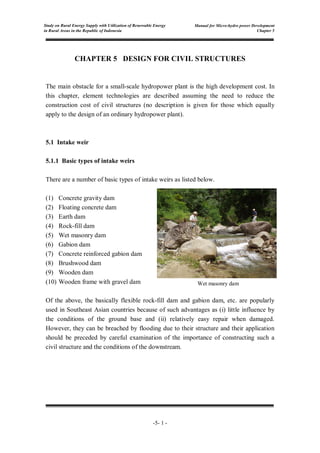
  • 1. Manual for Micro-hydro power Development Chapter 5 -5- 1 - Study on Rural Energy Supply with Utilization of Renewable Energy in Rural Areas in the Republic of Indonesia CHAPTER 5 DESIGN FOR CIVIL STRUCTURES The main obstacle for a small-scale hydropower plant is the high development cost. In this chapter, element technologies are described assuming the need to reduce the construction cost of civil structures (no description is given for those which equally apply to the design of an ordinary hydropower plant). 5.1 Intake weir 5.1.1 Basic types of intake weirs There are a number of basic types of intake weirs as listed below. (1) Concrete gravity dam (2) Floating concrete dam (3) Earth dam (4) Rock-fill dam (5) Wet masonry dam (6) Gabion dam (7) Concrete reinforced gabion dam (8) Brushwood dam (9) Wooden dam (10) Wooden frame with gravel dam Of the above, the basically flexible rock-fill dam and gabion dam, etc. are popularly used in Southeast Asian countries because of such advantages as (i) little influence by the conditions of the ground base and (ii) relatively easy repair when damaged. However, they can be breached by flooding due to their structure and their application should be preceded by careful examination of the importance of constructing such a civil structure and the conditions of the downstream. Wet masonry dam
  • 2. Manual for Micro-hydro power Development Chapter 5 -5- 2 - Study on Rural Energy Supply with Utilization of Renewable Energy in Rural Areas in the Republic of Indonesia Table 5.1.1 Basic types of intake weirs for small-scale hydropower plant and application conditions Type Outline Drawing Application Conditions Concrete gravity dam Concrete is used for the construction of the entire body. Foundations: in principle, bedrock River conditions: not affected by the gradient, discharge or level of sediment load Intake conditions: good interception performance and intake efficiency Floating concrete dam Lengthened infiltration path of the foundations by means of cut-off, etc. to improve the interception performance Foundations: in principle, gravel River conditions: not affected by the gradient, discharge or level of sediment load Intake conditions: good interception performance and intake efficiency Earth dam Earth is used as the main material for the body; the introduction of a riprap and core wall may be necessary depending on the situation. Foundations: variable from earth to bedrock River conditions: gentle flow and easy to deal with flooding Intake conditions: good intake efficiency because a high interception performance is possible with careful work
  • 3. Manual for Micro-hydro power Development Chapter 5 -5- 3 - Study on Rural Energy Supply with Utilization of Renewable Energy in Rural Areas in the Republic of Indonesia Type Outline Drawing Application Conditions Rock-fill dam Gravel is used as the main material for the body. The introduction of a core wall may be necessary depending on the situation. Foundations: various, from earth to bedrock River conditions: river where an earth dam could be washed away by the normal discharge Intake conditions: limited to the partial use of river water due to the low intake efficiency Wet masonry dam Filling of the spaces between gravel with mortar, etc. Foundations: various, from earth to bedrock River conditions: not affected by the gradient, discharge or level of sediment load Intake conditions: good interception performance and intake efficiency Gabion dam Gravel is wrapped by a metal net to improve the integrity. Foundations: various, from earth to bedrock River conditions: river where a rock- fill dam could be washed away by the normal discharge Intake conditions: limited to the partial use of river water due to the low intake efficiency Concrete reinforced gabion dam Reinforcement of the gabion surface with concrete Foundations: various, from earth to bedrock River conditions: river where the metal net could be damaged due to strong flow Intake conditions: applicable when a high intake efficiency is required
  • 4. Manual for Micro-hydro power Development Chapter 5 -5- 4 - Study on Rural Energy Supply with Utilization of Renewable Energy in Rural Areas in the Republic of Indonesia Type Outline Drawing Application Conditions Brushwood dam Simple weir using locally produced tree branches, etc. Foundations: various, from earth to gravel layer River conditions: loss due to flooding is assumed Intake conditions: at a site with a low intake volume or intake from a stream to supplement the droughty water flow Wooden dam Weir using wood Foundations: various, from earth to bedrock River conditions: relatively gentle flow with a low level of sediment transport Intake conditions: a certain level of intake efficiency is secured with a surface coating, etc. Wooden frame with gravel dam The inside of the wooden frame is filled with gravel to increase the stability. Foundations: various, from earth to bedrock River conditions: river at which a rock-ddddfill dam could be washed away by the normal discharge Intake conditions: limited to the partial use of river water due to the low intake efficiency 5.1.2 Decision on weir height As the weir volume is proportionate to the square of the height, it is important to decide the weir height in view of its minimisation taking the following conditions into consideration. (1) Conditions restricting waterway elevation
  • 5. Manual for Micro-hydro power Development Chapter 5 -5- 5 - Study on Rural Energy Supply with Utilization of Renewable Energy in Rural Areas in the Republic of Indonesia To decide the weir height, it is necessary to take the topographical and geological conditions of the waterway route into consideration in addition to the conditions at the weir construction site. Careful examination is particularly necessary at a site where the waterway construction cost accounts for a large proportion of the total construction cost. The weir height at a site where the waterway is constructed under an existing road is often decided with reference to the elevation of such a road. (2) Possibility of riverbed rise in downstream As the weir height for a small-scale hydropower plant is generally low, there is concern that its normal function could be disrupted by a rise of the riverbed in the downstream. Accordingly, the future riverbed rise should be assumed to decide the weir height if the planned site falls under any of the following cases. 1) Gently sloping river with a high level of transported sediment 2) Existence of not fully filled check dam, etc. in the downstream of the planned intake weir 3) Existence of a collapsing site in the downstream with concern in regard to continuous collapse in the future 4) Existence of a narrow section in the downstream which obstructs the flow of sediment and/or driftwood (3) Conditions to remove sediment from front of weir and settling basin by intake method (Tyrolean intake and side intake) Under normal circumstances, the weir height should be planned to exceed the calculated value by the following method to ensure the smooth removal of sediment from the front of the weir and the settling basin. 1) Side intake In the case of side intake, the following Case (a) or Case (b), which ever is the higher, is adopted. a. Weir height (D1) determined in relation to the bed elevation of the scour gate of the intake weir D1 = d1 + hi
  • 6. Manual for Micro-hydro power Development Chapter 5 -5- 6 - Study on Rural Energy Supply with Utilization of Renewable Energy in Rural Areas in the Republic of Indonesia b. Weir height (D2) determined by the bed gradient of the settling basin D2 = d2 + hi+ L (ic – ir) Where, d1 : height from the bed of the scour gate to the bed of the inlet (usually 0.5 – 1.0 m) d2 : difference between the bed of the scour gate of the settling basin and the riverbed at the same location (usually around 0.5 m) hi : water depth of the inlet (usually determined to make the inflow velocity approximately 0.5 – 1.0 m/s) L : length of the settling basin (see Chapter 5-5.3 and Fig.5.3.1) ic : inclination of the settling basin bed (usually around 1/20 – 1/30) ir : present inclination of the river Fig.5.1.1 Sectional view of side intake and weir Inlet L ic ir d2 d1 hi
  • 7. Manual for Micro-hydro power Development Chapter 5 -5- 7 - Study on Rural Energy Supply with Utilization of Renewable Energy in Rural Areas in the Republic of Indonesia 2) Tyrolean intake A Tyrolean intake where water is taken from the bottom assumes that the front of the weir is filled with sediment and, therefore, Case D2 determines the weir height for side intake. D2 = d2 + hi + L (ic – ir) Fig.5.1.2 Sectional view of Tyrolean intake and weir (4) Influence on electric energy generated At a site where the usable head is small or where it is planned to secure the necessary head by a weir, the weir height significantly influences the level of generated electric energy. Accordingly, it is necessary to determine the weir height at such a site by comparing the expected changes of both the construction cost and the generated electric energy because of different weir heights. (5) Influence of back water When roads, residential land, farmland and bridges, etc. exist in a lower elevation area in the upstream of a planned intake weir site, it is necessary to determine the weir height to prevent flooding due to back water. Particularly at a site with a high weir height, the degree of influence on the above features must be checked by means of back water calculation or other methods. Inlet L ic ir d2 D2 hi
  • 8. Manual for Micro-hydro power Development Chapter 5 -5- 8 - Study on Rural Energy Supply with Utilization of Renewable Energy in Rural Areas in the Republic of Indonesia 5.2 Intake 5.2.1 Intake method Apart from the ordinary side intake method, there are several types of simple intake methods which aim at reducing the weir height and omitting the intake gate (hereinafter referred to as the Tyrolean intake method) for a hydropower plant. Two typical examples are listed below. • Bar screen type • Bar-less type The details of these two types are shown in Table 5.2.1.
  • 9. Manual for Micro-hydro power Development Chapter 5 Study on Rural Energy Supply with Utilization of Renewable Energy in Rural Areas in the Republic of Indonesia Table 5.2.1 Typical examples of Tyrolean intake methods Intake Method Outline Drawing Characteristics Advantages and Problems Found by Actual Performance Survey Bar screen type • If a screen is installed to cover most of the river channel, it is highly resistant to riverbed fluctuations. A sufficiently wide intake width enables 100% intake of river water. As overflow may occur due to fallen leaves, etc. gathering on the screen surface, the screen width should have a sufficient margin. The sedimentation capacity of the weir to deal with sediment inflow should also be analysed. • This type is popularly used and the intake rate is said to be generally 0.1 – 0.3 m 3 /s per unit width based on a bar installation angle of up to 30°, an inter-bar space of 20 – 30 mm and a bar length of approximately 1 m. < Advantages > • A scour gate of intake weir can be omitted. • A compact intake facility is suitable for a narrow or rapid river. • Stable intake is possible despite a change of the riverbed upstream. < Problems > • At the time of flooding or water discharge, sediment and litter flow into the waterway. • A screen which is clogged with gravel, etc. requires much labour for its removal. Bar-less type • The running water usually overflows the fixed weir top and is guided into the settling basin via an intake channel placed across the river channel and along the endsill (deflector). With an increase of the river discharge, the running water overflows the endsill and eventually becomes a rapid flow to fly over the endsill, making intake impossible at the time of flooding. However, sediment deposited in the intake channel is washed away towards the downstream of the endsill, making maintenance of the intake channel easier. While the sectional form of this type is similar to that of the bar screen type, the absence of a screen means a reduction of the maintenance cost and labour related to the screen. < Advantage) • A compact intake facility is suitable for a narrow or rapid river. • Stable intake is possible despite a change of the riverbed upstream. • Sediment and litter are discharged naturally at the time of flooding. < Problem > • Plenty of sediment and litter inflow to the waterway. • Frequently of scouring of settling basin is required. -5- 9 -
  • 10. Manual for Micro-hydro power Development Chapter 5 -5- 10- Study on Rural Energy Supply with Utilization of Renewable Energy in Rural Areas in the Republic of Indonesia 5.2.2 Important points for intake design For the design of the intake for a small-scale hydropower plant, it is necessary to examine the possible omission of an intake gate and others in order to achieve cost reduction. In the case of a small-scale hydropower plant, the headrace tends to be an open channel, a covered channel or a closed conduit. When this type of headrace is employed, it is essential to avoid a water inflow volume which considerably exceeds the design intake volume as it will directly lead to the destruction of the headrace. Meanwhile, as automatic gate control for a small-scale hydropower plant results in a cost increase, manual control is opted for. In the case of the intake facility for a small- scale hydropower plant being constructed in a remote mountain area, a swift response to flooding is difficult. The following method is, therefore, proposed to control the inflow at the time of flooding without the use of a gate, etc. (1) Principle This method intends the design of an intake which becomes an orifice with a rise of the river water level due to flooding and is frequently used for a Tyrolean intake or for small-scale hydropower plants in Indonesia. The inflow volume in this case is calculated by the formula below. H Q f= Ai ×Cv × Ca × (2 ×g × H ) 0.5 Where, Qf : inflow volume of submerged orifice (m3 /s) Ai : area of intake (m2 ) Ai=bi × (dh + hi) dh=0.10~0.15m Flood Water Level → Water Level of Spillway Normal Water Level Bsp hsp Ai hi dh dh hi bi
  • 11. Manual for Micro-hydro power Development Chapter 5 -5- 11- Study on Rural Energy Supply with Utilization of Renewable Energy in Rural Areas in the Republic of Indonesia Cv : coefficient of velocity: Cv = 1/(1 + f) f : coefficient of inflow loss (see next figure) Bsp, hsp: refer to Chapter 5-5.3 Settling basin Fig.5.2.1 Coefficient of inflow loss of various inlet form Ca : coefficient of contraction (approximately 0.6; see the following formula) where, D, d: ratio between upstream flow and downstream flow of contracting flow when, d << D, Ca = 0.582 H: water level difference between upstream and downstream of the orifice (m) (2) Equipment outline The important points for design are listed below. 1) It is necessary for the intake to have a closed tap instead of an open tap so that it becomes a pressure intake when the river water level rises. 2) The intake should be placed at a right angle to the river flow direction where possible so that the head of the approaching velocity at the time of flooding is minimised. 3) As water inflow at the time of flooding exceeds the design intake volume, the spillway capacity at the settling basin or starting point of the headrace should be fairly large. Angularity Haunch Rounded Bellmouth Protruding f = 0.1 (round) - 0.2 (orthogon) f = 0.5 f = 0.25 f = 0.05 – 0.01 f = 0.1 f = 0.5 + 0.3 cosθ + 0.2 cos2 θ θ Ca = 0.582 + (Merriman’s formula) 0.0418 1.1 + d/D
  • 12. Manual for Micro-hydro power Development Chapter 5 -5- 12- Study on Rural Energy Supply with Utilization of Renewable Energy in Rural Areas in the Republic of Indonesia 5.3 Settling basin The settling basin must have not only a structure which is capable of settling and removing sediment which is a size larger than the minimum size which could have an adverse impact on the turbine, etc. but also a spillway to prevent excessive water inflow into the headrace. The basic configuration of a settling basin is illustrated below. Fig.5.3.1 Basic configuration of settling basin [Refference] In oblong section, uniform flow depth: ho1=H*×0.1/(SLs)0.5 H* : refer to {Ref.5-1} SLs : slope of top end of the headrace ho2={(α×Qd2 )/(g×B2 )}1/3 α=1.1 Qd= Design Discharge (m3 /s) g=9.8 Conduit section Widening section Settling section B b 1.0 2.0 Dam Spillway Stoplog Flushing gate Intake Headrace Bsp hs hsp+15cm h0 10~15 cm hi ic=1/20~1/30 Intake Stoplog bi Lc Lw Ls L Sediment Pit Flushing gate
  • 13. Manual for Micro-hydro power Development Chapter 5 -5- 13- Study on Rural Energy Supply with Utilization of Renewable Energy in Rural Areas in the Republic of Indonesia B:Width of Headrace (m) if ho1<ho2, ho=ho1 if ho1≦ho2, ho=ho2 Each of these sections has the following function. (1) Conduit section Conduit section connects the intake with the settling basin. It is necessary that the conduit section should be curtailing its length. (2) Widening section: This regulates water flow from the conduit channel to prevent the occurrence of whirlpools and turbulent flow and reduces the flow velocity inside the settling basin to a predetermined velocity. (3) Settling section: This section functions to settle sediment above a certain size and its required length (l) is calculated by the following formula based on the relation between the settling speed, flow velocity in the settling basin and water depth. The length of the settling basin (Ls) is usually determined so as to incorporate a margin to double the calculated length by the said formula. Where, l : minimum length of settling basin (m) hs : water depth of settling basin (m) ( -see Fig.5.31) U : marginal settling speed for sediment to be settled (m/s) usually around 0.1 m/s for a target grain size of 0.5 – 1 mm. V : mean flow velocity in settling basin (m/s) usually around 0.3 m/s but up to 0.6 m/s is tolerated in the case where the width of the settling basin is restricted. V = Qd/(B×hs) Qd: design discharge (m3 /s) B : width of settling basin (m) l ≥ ×hs L s= 2×l V U
  • 14. Manual for Micro-hydro power Development Chapter 5 -5- 14- Study on Rural Energy Supply with Utilization of Renewable Energy in Rural Areas in the Republic of Indonesia (4) Sediment pit: This is the area in which sediment is deposited. (5) Spillway Spillway drains the submerged inflow which flows from the intake. The sizes of spillway will be decided by following equation. Qf= C×Bsp×hsp1.5 →hsp={Qf /(C×Bcp)}1/1.5 Where, Qf : inflow volume of submerged orifice (m3 /s, see Chapter 5-5.2.2 (1)) C : coefficient =1.80 hsp: water depth at the spillway (m, see Fig 5.3.1) Bsp: width of the spillway (m, see Fig.5.3.1)
  • 15. Manual for Micro-hydro power Development Chapter 5 -5- 15- Study on Rural Energy Supply with Utilization of Renewable Energy in Rural Areas in the Republic of Indonesia 5.4 Headrace 5.4.1 Type and Basic Structure of Headrace Because of the generally small amount of water conveyance, the headrace for a small- scale hydropower plant basically adopts an exposed structure, such as an open channel or a covered channel, etc. Some examples and their basic structures are given in Table 5.4.1 and Table 5.4.2 respectively.
  • 16. Manual for Micro-hydro power Development Chapter 5 Study on Rural Energy Supply with Utilization of Renewable Energy in Rural Areas in the Republic of Indonesia Table 5.4.1 Types of headraces for small-scale hydropower plants Type Outline Drawing Advantages and Problems Typical Structure Open channel < Advantages > • Relatively inexpensive • Easy construction < Problems > • Possible inflow of sediment from the slope above • High incursion rate of fallen leaves, etc. • Simple earth channel • Lined channel (dry or wet masonry lining; concrete lining) • Fenced channel (made of wood, concrete or copper) • Sheet-lined channel • Half-tube channel (corrugated piping, etc.) Closed conduit / Covered channel < Advantages > • Generally large earth work volume • Low incursion rate of sediment and fallen leaves, etc. into the channel < Problems > • Less easier channel inspection, maintenance work, including sediment removal, and repair • Buried tube (Hume, PVC or FRPM) • Box culvert • Fenced channel with cover -5- 16 -
  • 17. Manual for Micro-hydro power Development Chapter 5 -5-17- Study on Rural Energy Supply with Utilization of Renewable Energy in Rural Areas in the Republic of Indonesia Table 5.4.2 Basic structure of headraces for small-scale hydropower plants Type Outline Diagram Advantages and Problems Simple earth channel < Advantages > • Easy construction • Inexpensive • Easy repair < Problems > • Possible scouring or collapse of the walls • Not applicable to highly permeable ground • Difficult to mechanise the sediment removal work Lined channel (rock and stone) < Advantages > • Relatively easy construction • Can be constructed using only local materials • High resistance to side scouring • Relatively easy repair < Problems > • Not applicable to highly permeable ground Wet masonry channel < Advantages > • Local materials can be used • Strong resistance to back scouring • Can be constructed on relatively high permeable ground. • Easy construction at the curved section due to the non-use of forms < Problems > • More expensive than a simple earth channel or dry masonry channel (rock/stone-lined channel) • Relatively takes labour hours. Concrete channel < Advantages > • High degree of freedom for cross- section design < Problems > • Difficult construction when the inner diameter is small • Relatively long construction period n=0.030 n=0.025 Plastered : n=0.015 Non Plastered : n=0.020 n=0.015
  • 18. Manual for Micro-hydro power Development Chapter 5 -5-18- Study on Rural Energy Supply with Utilization of Renewable Energy in Rural Areas in the Republic of Indonesia Type Outline Diagram Advantages and Problems Wood fenced channel < Advantages > • Less expensive than a concrete channel • Flexible to allow minor ground deformation < Problems > • Limited use with earth foundations • Unsuitable for a large cross-section • Difficult to ensure perfect water- tightness • Liable to decay Box culvert channel < Advantages > • Easier construction than a Hume pipe on a slope with a steep cross- sectional gradient • Relatively short construction period and applicable to a small cross- section when ready-made products are used • Rich variety of ready-made products < Problems > • Heavy weight and high transportation cost when ready-made products are used • Long construction period when box culverts are made on site Hume pipe channel < Advantages > • Easy construction on a gently sloping site • Relatively short construction period • High resistance to external pressure • Applicable to a small cross-section • Elevated construction with a short span is possible < Problems > • Heavy weight and high transportation cost n=0.015 n=0.015 n=0.015
  • 19. Manual for Micro-hydro power Development Chapter 5 -5-19- Study on Rural Energy Supply with Utilization of Renewable Energy in Rural Areas in the Republic of Indonesia 5.4.2 Determining the Cross Section and Longitudinal Slope The size of cross section and slope should be determined in such a manner that the required turbine discharge can be economically guided to the head tank. Generally, the size of cross section is closely related to the slope. The slope of headrace should be made gentler for reducing head loss (difference between water level at intake and at head tank) but this causes a lower velocity and thus a lager cross section. On the contrary, a steeper slope will create a higher velocity and smaller section but also a lager head loss. Generally, in the case of small-hydro scheme, the slope of headrace will be determined as 1/500 – 1/1,500. However in the case of micro-hydro scheme, the slope will be determined as 1/50 – 1/500, due to low skill on the survey of levelling and construction by local contractor. The cross section of headrace is determined by following method. (1) Method of calculation Qd= A ×R 2/3 ×SL 1/2 /n Qd : design discharge for headrace (m3 /s) A : area of cross section (m2 ) R : R=A/P (m) P : length of wet sides (m) refer to next figure. SL : longitudinal slope of headrace (e.g. SL= 1/100=0.01) n : coefficient of roughness (see Table 5.4.2) For instance, in the case of rectangular cross section, width (B)=0.6m, water depth (h)=0.5m, longitudinal slope (SL)=1/200=0.005, coefficient of roughness (n)=0.015. A= B×h = 0.6 × 0.5 = 0.30 m2 P= B + 2 × h = 0.6 + 2 × 0.5 =1.60 m R= A/P = 0.30/1.60 = 0.188 m ∴ Qd= A ×R 2/3 ×SL 1/2 /n = 0.30 ×1.60 2/3 ×0.005 1/2 /0.015 = 1.94 m3 /s Water surface : P
  • 20. Manual for Micro-hydro power Development Chapter 5 -5-20- Study on Rural Energy Supply with Utilization of Renewable Energy in Rural Areas in the Republic of Indonesia (2) Simple method In order to simplify the above method, following method for determining the cross section is used in [Reference 5-1 Simple Method for Determining the Cross Section] This reference will be used in determination of cross section in the following two sectional forms. Rectangular cross section Trapezoid cross section H* should be calculated on each different slope. For instance, in the case of trapezoid cross section, design discharge (Q)=0.5m3 /s, width (B)=0.8m, longitudinal slope (SLA,B,C,D)=1/100, 1/50, 1/100, 1/200 which is the gentlest position of the headrace, coefficient of roughness (n)=0.015. Water depth (H*) is approximately 0.3m in Reference 5-1 Fig-4. Therefore actual water depth (H) is H = H* × 0.1 /(SL)0.5 HA,C = H* × 0.1 /(SLA,C)0.5 = 0.3×0.1/(0.01) 0.5 = 0.3 HB = H* × 0.1 /(SLB)0.5 = 0.3×0.1/(0.02) 0.5 = 0.21 HD = H* × 0.1 /(SLD)0.5 = 0.3×0.1/(0.005) 0.5 = 0.42 and height of the cross section of Slope A,C is 0.60m(0.3+0.2~0.3), height of the cross section of Slope B is 0.55m(0.21+0.2~0.3), height of the cross section of Slope D is 0.75m(0.42+0.2~0.3). B=0.6 and 0.8m 1.0 m=0.5 B=0.6 and 0.8m Slope A Slope B Slope C Slope D SLA = 1/100 SLB = 1/50 SLC = 1/100 SLD = 1/200
  • 21. Manual for Micro-hydro power Development Chapter 5 -5-21- Study on Rural Energy Supply with Utilization of Renewable Energy in Rural Areas in the Republic of Indonesia 5.5 Head Tank 5.5.1 Head tank capacity (1) Function of headtank The functions of headtank are roughly the following 2 items. • Control difference of discharge in a penstock and a headrace cause of load fluctuation. • Finally remove litter (earth and sand, driftwood, etc.) in flowing water (2) Definition of head tank capacity The head tank capacity is defined the water depth from hc to h0 in the head tank length L as shown in Fig.5.5.1. Fig.5.5.1 Picture of headtank capacity 0.5 1.0 dsc As d Bspw hc h0 h>1.0×d S=1~2×d 1.0 20.0 B L 1.0 2.0 30~50cm b B-b Headrace 30~50cm Ht Spillway Screen SLe h0=H*×0.1/(Sle) 0.5 H*:Refer to 'Reference 5-1' hc={(α×Qd2 )/(g×B2 )}1/3 α=1.1 g=9.8 d=1.273×(Qd/Vopt)0.5 Vopt:Refer to 'Reference 5-2' Vsc=As×dsc=B×L×dsc≧10sec×Qd B,dsc:desided depend on site condition.
  • 22. Manual for Micro-hydro power Development Chapter 5 -5-22- Study on Rural Energy Supply with Utilization of Renewable Energy in Rural Areas in the Republic of Indonesia Headtank capacity Vsc = As×dsc=B×L×dsc where, As: area of headtank B : width of headtank L : length of headtank dsc: water depth from uniform flow depth of a headrace when using maximum discharge (h0) to critical depth from top of a dike for sand trap in a headtank (hc) [Reference] In oblong section, uniform flow depth: ho=H*×0.1/(SLe)0.5 H* : refer to {Ref.5-1} SLe : slope of tail end of the headrace critical depth: hc={(α×Qd2 )/(g×B2 )}1/3 α: 1.1 g : 9.8 (3) Determine a headtank capacity The headtank capacity should be determined in consideration of load control method and discharge method as mentioned below. a. In case only load is controlled In the case where only controlled load (demand) fluctuation has been considered, generally a dummy load governor is adopted. A dummy load governor is composed of water-cooled heater or air-cooled heater, difference of electric power between generated in powerhouse and actual load is made to absorb heater. The discharge control is not performed. The head tank capacity should be secured only to absorb the pulsation from headrace that is about 10 times to 20 times of the design discharge (Qd). A view showing a frame format of load controlled by a dummy load governor is shown in Fig.5.5.2. Fig.5.5.2 Pattern diagram of dummy load consumption Generated power Dummy load consumption Time Power demand Electric power Water discharge
  • 23. Manual for Micro-hydro power Development Chapter 5 -5-23- Study on Rural Energy Supply with Utilization of Renewable Energy in Rural Areas in the Republic of Indonesia b. In case both load and discharge are controlled In the case of controlled load and discharge, a mechanical governor or electrical governor is used for load control. These governors have the function of controling vane operation to optimal discharge when electrical load has changed. Generally a mechanical governor is not sensitive to load change, and head tank capacity in this case should be secured 120 times to 180 times of Qd. On the other hand, an electrical governor is responsive to load change, therefore head tank capacity is designed about 30 times to 60 times of Qd in many cases. 5.5.2 Important issues for head tank design The design details for the head tank for a small-scale hydropower plant are basically the same as those for a small to medium-scale hydropower plant and the particularly important issues are discussed below. (1) Covering water depth and installation height of penstock inlet As the penstock diameter is generally small (usually 1.0 m or less) in the case of a small-scale hydropower plant, it should be sufficient to secure a covering water depth that is equal to or larger than the inner diameter of the penstock. However, in the case of a channel where both the inner diameter and inclination of the penstock are as large as illustrated below, the occurrence of inflow turbulence has been reported in the past. Accordingly, the covering water depth must be decided with reference to the illustration below when the inner diameter of the penstock exceeds 1.0 m. Vertical angle Swirly when Qmax
  • 24. Manual for Micro-hydro power Development Chapter 5 -5-24- Study on Rural Energy Supply with Utilization of Renewable Energy in Rural Areas in the Republic of Indonesia h = d2 Where, h : water depth from the centre of the inlet to the lowest water level of the head tank = covering water depth (m) d : inner diameter of the penstock (m) • Covering Water Depth The covering water depth at the penstock inlet must be above the following value to prevent the occurrence of inflow turbulence. d ≤ 1.0 m → h ≥ 1.0 d d > 1.0 m → h ≥ d2 Where, h : water depth from the centre of the inlet to the lowest water level of the head tank = covering water depth (m) d : inner diameter of the penstock (m) • Installation height of penstock There are many reports of cases where inappropriate operation has caused the inflow of sediment into the penstock, damage the turbine and other equipment. Accordingly, it is desirable for the inlet bottom of the penstock to be placed slightly higher than the apron of the head tank (some 30 – 50 cm). NWL LWL h 30~50cm d 1~2d
  • 25. Manual for Micro-hydro power Development Chapter 5 -5-25- Study on Rural Energy Supply with Utilization of Renewable Energy in Rural Areas in the Republic of Indonesia (2) Appropriate spacing of screen bars for turbine type, etc. The spacing of the screen bars (effective screen mesh size) is roughly determined by the gate valve diameter but must be finalised in consideration of the type and dimensions of the turbine and the quantity as well as quality of the litter. The reference value of an effective screen mesh size is shown below. Effective screen mesh size (reference) (3) Installation of vent pipe to complement head tank gate When a head tank gate is installed instead of a gate valve for a power station, it is necessary to install a vent pipe behind the head tank gate to prevent the rupture of the penstock line. In this case, the following empirical formula is proposed to determine the dimensions of the vent pipe. Where, d : inner diameter of the vent pipe (m) P : rated output of the turbine (kW) L : total length of the vent pipe (m) H : head (m) 200 400 600 800 1000 20 50 Gate Valve Diameter (mm) Effective Screen Mesh Size (mm) d = 0.0068 ( ) 0.273 P2 ・L H2
  • 26. Manual for Micro-hydro power Development Chapter 5 -5-26- Study on Rural Energy Supply with Utilization of Renewable Energy in Rural Areas in the Republic of Indonesia Source: Sarkaria, G.S., “Quick Design of Air Vents for Power Intakes”, Proc. A.S.C.E., Vol. 85, No. PO.6, Dec., 1959 (4) Spillway at the headtank Generally, the spillway will be installed at the head tank so that excessive quantity of water is discharged to the river safely when the turbine is stopped. The size of spillway is decided by following equation. Qd=C×Bspw×hspw 1.5 → hspw={Qd/(C×Bspw)}1/1.5 Qd : design discharge (m3 /s) C : cofficient, usually C=1.8 Bspw : width of spillway (m , refer to Fig 5.1.1) hspw : depth at the spillway (m)
  • 27. Manual for Micro-hydro power Development Chapter 5 -5-27- Study on Rural Energy Supply with Utilization of Renewable Energy in Rural Areas in the Republic of Indonesia 5.6 Penstock 5.6.1 Penstock material At present, the main pipe materials for a penstock are steel piping, ductile iron piping and FRPM (fibre reinforced plastic multi-unit) piping. In the case of a small-scale hydropower plant, the use of hard vinyl chloride piping, Howell piping or spiral welded piping can be considered because of the small diameter and relatively low internal pressure. The characteristics of each pipe material are shown in “Table 5.6.1 – Penstock pipe materials for small-scale hydropower plant”. 5.6.2 Calculation of steel pipe thickness The minimum thickness of steel pipe of penstock is determined by following formula. where, t0: minimum thickness of pipe P: design water pressure i.e. hydrostatic pressure + water hammer (kgf/cm2 ) , in micro-hydro scheme P=1.1×hydrostatic pressure. for instance, if the head (Hp, refer to following figure) from head tank to turbine is 25m, P=2.5×1.1=2.75 kgf/cm2 . d: inside diameter (cm) θa: admissible stress (kgf/cm2 ) SS400: 1300kgf/cm2 η: welding efficiency (0.85~0.9) δt : margin (0.15cm in general) 5.6.3 Determining the Diameter of Penstock Generally the diameter of penstock is determined by comparison between the cost of penstock and head loss at penstock. However a simple method for determining the diameter of penstock is indicated in [Reference 5-2 Simple Method for Determining the Diameter of Penstock] . The diameter of penstock will be determined from “Average angle of Penstock (Ap: see following figure) “ and “Design Discharge (Qd)”. t0 = + δt (cm) P×d 2×θa×η and t0=≧0.4cm or t0≧(d+80)/40 cm
  • 28. Manual for Micro-hydro power Development Chapter 5 -5-28- Study on Rural Energy Supply with Utilization of Renewable Energy in Rural Areas in the Republic of Indonesia For instance, in the case of design discharge (Qd)=0.50m3 /s,length of penstock (Lp)=60m, height from head tank to power house (Hp)=15m, average angle (Ap)=15/60=0.25, the optimum velocity (Vopt) is determined as about 2.32 in Reference 5-2. Therefore the diameter of penstock pipe (d) is d = 1.273 × (Qd/Vopt)0.5 =1.273 × (0.5/2.32)0.5 = 0.59 m Lp Head Tank Power House Hp Ap = Hp / Lp
  • 29. Manual for Micro-hydro power Development Chapter 5 Study on Rural Energy Supply with Utilization of Renewable Energy in Rural Areas in the Republic of Indonesia Table 5.6.1 Penstock pipe materials for small-scale hydropower plant Resin Pipe Iron Pipe Hard Vinyl Chloride Pipe Howell Pipe FRP Pipe Steel Pipe Ductile Iron Pipe Spiral Welded Pipe Characteristics • Most popular material for a pipeline as it is frequently used for water supply and sewer lines • Effective for a pipeline with a small discharge • Rich variety of ready-made irregular pipes • Often buried due to weak resistance to impact and large coefficient of linear expansion • Basically resistant to external pressure but ready-made pipes to resist internal pressure are available • Relatively easy fabrication of irregular pipes due to easy welding • Basically used as a buried pipe • Plastic pipe reinforced by fibre glass • Used as an exposed pipe and can be made lighter than FRPM pipe with a thinner wall as it is not subject to external load other than snow • Popular choice to penstock at a hydropower plant • Reliable material due to established design techniques • Often used for water supply, sewer, irrigation and industrial pipes • Generally used as a buried pipe although exposed use is also possible • High resistance to both external and internal pressure • Some examples of use for a pipeline • Mainly used as a buried pipe for appearance to hide a spiral welding line • Can be used as steel pipe piles Maximum Pipe Diameter (mm) Thick pipe: ∅300 Thin pipe: ∅800 ∅2,000 ∅3,000 approx. ∅3,000 ∅2,600 ∅2,500 Permissible Internal Pressure (kgf/cm 2 ) Thick pipe: 10 Thin pipe: 6 2.0 – 3.0 Class A: 22.5 133 approx. 40 15 Hydraulic Property (n) 0.009 – 0.010 0.010 – 0.011 0.010 – 0.012 (approx. 0.011 in general) 0.010 – 0.014 (approx. 0.012 in general) 0.011 – 0.015 (approx. 0.012 in general) - -5-29 -
  • 30. Manual for Micro-hydro power Development Chapter 5 Study on Rural Energy Supply with Utilization of Renewable Energy in Rural Areas in the Republic of Indonesia Resin Pipe Iron Pipe Hard Vinyl Chloride Pipe Howell Pipe FRP Pipe Steel Pipe Ductile Iron Pipe Spiral Welded Pipe Workability • Easy design and work due to light weight and rich variety of irregular pipes • Good workability due to light weight • Good workability due to light weight and no need for on-site welding as a specially formed rubber ring is used for pipe connection • Steel pipes are used for irregular sections because of the limited availability of irregular FRP pipes • Inferior workability to FRP pipes • Inferior workability to FRP pipes • Inferior workability to FRP pipes Water-tightness • Good water- tightness as bonding connection is possible • No problem of water-tightness at the joints • No problem of water-tightness as the joint connection method is established • No problem of water-tightness as the joint connection method is established • Good • No problems -5-30-
  • 31. - 5-31 - Study on Rural Energy Supply with Utilization of Renewable Energy in Rural Areas in the Republic of Indonesia Manual for Micro-hydro power Development Chapter 5 5.7 Foundation of Powerhouse Powerhouse can be classified into ‘the above ground type or the semi-underground type’ and ‘the under ground type’. Most small-scale hydro power house are the above ground type. The dimensions for the floor of powerhouse as well as the layout of main and auxiliary equipment should be determined by taking into account convenience during operation, maintenance and installation work, and the floor area should be effectively utilized. Various types of foundation for powerhouse can be considered depending on the type of turbine. However the types of foundation for powerhouse can be classified into ‘for Impulse turbine’ (such as Pelton turbine, Turgo turbine and cross flow turbine) and ‘for Reaction turbine’ (Francis turbine, propeller turbine). 5.7.1 Foundation for Impulse Turbine Fig.5.7.1 shows the foundation for cross flow turbine, which frequently is used in the micro-hydro scheme as an impulse turbine. In case of impulse turbine, the water passing by the runner, is directly discharged into air at tailrace. The water-surface under the turbine will be raged. Therefore the clearance between the slab of powerhouse and water-surface at the afterbay should be kept at least 30-50cm. The water depth (hc) at the afterbay can be calculated by following equation. hc: water depth at afterbay (m) Qd: design discharge (m3 /s) b : width of tailrace channel (m) The water level at afterbay should be set higher than the estimated flood water level. Then in case of impulse turbine, the head between the center of turbine and water level at the outlet becames the head-loss (HL3: refer to Ref.5-3). hc=( )1/3 1.1×Qd2 9.8×b2
  • 32. - 5-32 - Study on Rural Energy Supply with Utilization of Renewable Energy in Rural Areas in the Republic of Indonesia Manual for Micro-hydro power Development Chapter 5 Fig.5.7.1 Foundation of Powerhouse for Impulse Turbine (Crossflow turbine) 5.7.2 Foundation for Reaction Turbine Fig.5.7.2 (a) shows the foundation for Francis turbine, which is a typical turbine of the reaction turbine. The water is discharged into the afterbay through the turbine. In case of a reaction turbine, the head between center of turbine and water-level can be used for power generation. Then it is possible that the turbine is installed under the flood water level on condition that the following equipment is provided (see Fig. 5.7.2(b)). a. Tailrace gate b. Pump at powerhouse Flood Water Level(Maximum) 20cm bo Section A-A 20cm b bo: depends on Qd and He 30~50cm hc 30~50cm HL3 (see Ref.5-3) hc={ } 1/3 1.1×Qd 2 9.8×b 2 A A Afterbay Tailrace cannel Outlet
  • 33. - 5-33 - Study on Rural Energy Supply with Utilization of Renewable Energy in Rural Areas in the Republic of Indonesia Manual for Micro-hydro power Development Chapter 5 Fig 5.7.2(a) Foundation of powerhouse for Reaction Turbine (Francis turbine) Fig 5.7.2(b) The way of installation to Lower Portion as an Example Section A-A 1.5×d3 Flood Water Level(Maximum) 30~50cm hc 2×d3 d3 20cm 1.15×d3 1.5×d3 Hs Hs:depens on characteristic of turbine HL3 (see Ref.5- 3) hc={ } 1/3 1.1×Qd 2 9.8×b 2 A A Pump Gate HL3 Flood Water Level (Maxmum)