
Recommended
More Related Content
What's hot
What's hot (19)
Viewers also liked
Viewers also liked (18)
Similar to Efficient Use of Rain Water by Altering Channel System
Similar to Efficient Use of Rain Water by Altering Channel System (20)
Recently uploaded
Recently uploaded (20)
Efficient Use of Rain Water by Altering Channel System
- 1. The International Journal Of Engineering And Science (IJES) || Volume || 4 || Issue || 3 || Pages || PP.01-05 || 2015 || ISSN (e): 2319 – 1813 ISSN (p): 2319 – 1805 www.theijes.com The IJES Page 1 Efficient Use of Rain Water by Altering Channel System Abhay Dixit1 1 Author is affiliated to Maharishi Arvind College of Engg. And research centre, Sirsi road, Jaipur. ------------------------------------------------------------ABSTRACT--------------------------------------------------------- The standing water /water stagnation on road surface is always been a major problem .The stagnant water degrades the surface of the road resulting in the formation of the potholes and wear off the surface of the road .The major source of stagnant water is improper slope provided on the road. Moreover, due to heavy rains the water is left on the surface of the road which wears off the road surface. Therefore this paper concentrates on providing the effective way to collect this stagnant water and to modernize the conventional system of drainage. Keywords: drainage, potholes, slope, stagnant water. --------------------------------------------------------------------------------------------------------------------------------------- Date of Submission: 02-March-2015 Date of Accepted: 25.March.2015 --------------------------------------------------------------------------------------------------------------------------------------- I. INTRODUCTION:- Stagnation of rain water is a common phenomenon in most cities in plains. Rain water collects at depressions in roads and ditches on ground and drains out at a very slow pace due to poor ground slopes and lack of proper drainage of rain water. As water remains on roads, e.g. at locations of under passes, road junctions and spots, traffic is hampered. The stagnant water in the ditches becomes a breeding ground for mosquitoes at times, which leads to lot of diseases such as diarrhea, typhoid, and malaria. Ideally, storm water drains and sewerage system are different and should be considered accordingly. While sewage treatment is required before disposal but there is no such need for rain water except for screening which can be directly be used. Treating both the water puts additional pressure on sewage treatment plants and takes a lot of time in pumping the combined effluent into rivers or water courses due to their restricted pumping capacity. The efficient disposal of rain water and preventing water logging of roads is an important concern for highway engineers. The major priority of water management tells us that the rain water should be ‘used’ for recharging the ground water and been wasted as surface run off. Therefore, this research paper provides an efficient way of collecting the rain water from road by altering the slope of the roads and by changing the materials used for construction of road, which will replenish the water table. I. Drainage:- Drainage is the natural or artificial removal of surface and sub-surface water from an area. A storm drain or drain system is designed to drain excess rain water from roads and parking area. Storm drains differs in design from small residential dry wells to large municipal systems. This water is led to street gutters on motorways, freeways and other busy roads, as well as in areas which experience heavy rainfall. Many storm drainage systems are designed to drain the storm water into rivers or streams. There are two main types of storm water drain inlets: side inlets and grated inlets. Side inlets are located adjacent to the kerb and rely on the ability of the opening under the back stone or lintel to capture flow. They are usually depressed at the invert of the channel to improve capture capacity. Many inlets have grids to prevent people, vehicles, large objects or debris from falling into the storm drain. Grate bars are spaced so that the flow of water is not hampered. Pipes can also be used to drain off the water. These are available in different shapes and sizes viz rectangular, square, bread-loaf-shaped, oval, inverted pear-shaped, egg shaped, and circular. Pipes made of different materials can also be used, such as brick, concrete, high-density polyethylene or galvanized steel. Fibre reinforced plastic is now a day widespread used for drain pipes and fittings.
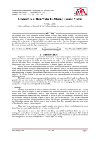
- 2. Efficient Use of Rain Water by Altering Channel System www.theijes.com The IJES Page 2 II. Potholes:- A pothole is a type of failure on road surface mainly caused due to the presence of water in the sub soil structure and the presence of traffic passing over the same area. Introduction of water to the sub soil structure first affects the supporting soil and then reversal of stresses take place due to traffic which worsens the situation and breaks the road/pavement surface in the affected area. Prolong traffic action bring out both the mortar and the underlying soil material to create a hole in the pavement. Fig1: Formation of potholes A systematic picture of the formation of potholes is shown above. The picture depicts the precipitation on the sub base and the second and third shows how the fatigues happen and strike on the surface of the pavement. The fourth on shows the effect of prolong traffic hit on it. In order to repair these potholes, Pothole patching methods is used which is of two types: temporary and semi-permanent. Temporary patching method is used only for weather conditions that are not favorable to a more permanent solution and uses a cold mix mortar patching compound, placed in an expedient order to temporarily regain pavement smoothness. Semi-permanent patching is applied carefully in re-constructing the perimeter of the affected area to mix with the surrounding pavement and uses a hot-mix mortar filled above replacement of base materials. i. Materials: Asphalt patch materials consist of a binding agent and aggregate that comes in two broad categories, hot mix and cold mix. Hot mixes are used by some firms; they are produced at localized asphalt plants. The FHWA manual have three types of cold mixes, those which are produced by a local asphalt plant, by 1) using the available aggregate and binder and 2) according to specifications set by the institute that will use the mix. The third type is an individual cold mix, which is manufactured to an advertised level. ii. Throw-and-roll repair: The FHWA manual states the throw-and-roll method as the crucial basic method, best used as a temporary repair method under conditions where it is difficult to control the placement of material, such as winter-time. Its procedure is: 1. Placing the hot or cold patch material into a pothole. 2. Compacting the patch with a vehicle, such as a truck. 3. Achieving a crown on the compacted patch of between 3 and 6 mm. iii.Semi-permanent repair: The FHWA manual states the semi-permanent repair method as one of the benevolent method for repairing potholes. Its procedure is:
- 3. Efficient Use of Rain Water by Altering Channel System www.theijes.com The IJES Page 3 1. Removing water and debris from the pothole. 2. Making clean cuts along the sides of prospective patch area to assure that vertical sides of the repair are in sound pavement. 3. Placing the hot or cold patch mix material. 4. Compacting the patch with a device that is smaller than the patch area, e.g. vibratory rollers or a vibratory plate. While this repair procedure provides promising results, it requires more labour and equipment than the throw- and-roll or the spray-injection procedure. iv. Spray-injection repair The FHWA manual states the spray-injection procedure as an efficient substitute to semi-permanent repair. It requires specialized equipment, however. It consists of: 1. Blowing water and debris from the pothole. 2. Spraying a tack coat of binder on the sides and bottom of the pothole. 3. Blowing asphalt and aggregate into the pothole. 4. Covering the patched area with a layer of aggregate. This procedure requires no compaction after the cover aggregate has been placed. v. Edge seal repair: The FHWA manual states the edge seal method as a substitute to the above techniques. It consists of: 1. Following the "throw-and-roll" steps. 2. after the repaired section has dried, placing a ribbon of asphaltic tack material on top of the patch edge, overlapping the pavement and the patch. 3. Placing sand on the tack material to prevent tracking by vehicle tires. In this procedure, waiting for any water to dry may require an inspection in order to place the tack coat. The tack material prevents water from getting through the edge of the patch and helps in bonding the patch to the pavement. III. Slope:- The slope also known as grade, incline, gradient or rise of a physical feature, landform or constructed line refers to the inclination of the surface to the horizontal. It is a special case of the gradient in calculus where zero indicates gravitational level. A larger number indicates higher or steeper degree of "tilt". In the case of pavements this plays a vital role in providing the drainage so that prolonged water does not affect the sub soil leading to the formation of potholes, moreover slope is provide in so that the flora and fauna is not affected .but in this particular case we are talking about this because slope helps n getting rid of the storm water. Cross slope or camber is a geometric feature of pavement surfaces: the transverse slope with respect to the horizon. It is a very important safety factor. Cross slope is provided to provide a drainage gradient so that water will drain from the surface to a drainage system such as a street gutter . Inappropriate cross slope will lead to aquaplaning. On straight sections of two-lane roads, the pavement’s cross section is usually maximum in the centre and drains from both the sides. In horizontal curves, the cross slope is banked into super elevation to reduce steering effort and lateral force is required to go around the curve. All water runs off to the inside of the curve. If the cross slope magnitude oscillates within 1–25 metres, the body and payload of heavy vehicles will experience high roll vibration. Cross Slope is the angle in the vertical plane from a horizontal line to a line on the surface, which is perpendicular to the centre line. IV. Stagnant water:- Water stagnation occurs when water stops flowing. Stagnant water can be a major environmental hazard; it can cause mosquitoes to breed and reproduce that may lead to dengue. But here we are talking about stagnant water because it degrades the soil sub base which leads to the formation of the potholes.
- 4. Efficient Use of Rain Water by Altering Channel System www.theijes.com The IJES Page 4 i. Causes and prevention of stagnant water: Stagnant water may be classified into the following basic, although overlapping, types: Surface and ground water stagnation. Trapped water stagnation. The water may be trapped in human artifacts (thrown away cans, plant pots, tires, roofs, etc.). To avoid ground and surface water stagnation, water runoff from surface and subsoil should be proper. Areas with a shallow water table are more prone to ground water stagnation due to the lower availability of natural soil drainage. II. THEORY: This research paper intend to give an alternative way of preventing the formation of potholes as well as saving the expenses/cost it takes to repair these potholes at that the time using this storm water in order to meet the surplus demand of water in a desert like state or remote areas or in drought like places. The main idea is that providing a channel on the sub surface of the soil formed by using the cement the channel is then divided into half and the special type of the stones, which have a hole in centre to provide a gap for the flow of water through it, that are placed on the it, providing suitable gap between the channel and the stone .the gap should be according to the water it receives in the rainy season. Both the sides of the channel are fitted with long rod of pre stressed concrete in order to transfer the load caused by the moving vehicles and at last ballast is added on either sides of the channel to transfer the load of vehicles. Just like the transfer of load occurs on the railway tracks. Therefore , the storm water no longer provide a hindrance to the traffic , there will be no potholes formation , stagnant water will not be there thereby reducing the amount t of disease caused by the standing water such as dengue and the scarcity of water can be met. III. PROCEDURE: The earth surface is dug up to a height of 10 feet. Leveling of the sub soil is done and course action is prepared. A channel is made with cement coating such that the surface of it becomes smooth. The width of the channel is taken according to traffic flow it is likely to take. The channel is then divided into half with a wall, such that the opening of the channel and the height of the wall. Large pre stressed concrete rod are placed onto the edges of the channel spanning horizontally such that the ends of these rods are buried properly inside the leveled soil present on both sides f the channel . The large stone are kept on the opened surface of the channel, in order to cover the channel properly. These large stone are then attached with each other with the filling of the mortar. The holes are crafted on the top facing of these stone and the grinding is done on the surface of the stones to provide a slope of 1:25. Ballast is added on both side of the channel. Therefore the storm water can now flow easily from these open channels without affecting the traffic flow, the standing water problem is also solved as well. IV. PROBLEMS:- The cost of constructing these channels and linking it to the other channel is high. V. ADVANTAGES:- Collecting the storm water will reduce the scarcity of water. Traffic flow will not be affected due to storm water. Diseases such as malaria, dengue which is the main cause of standing water will be controlled. Annual cost of repairing potholes will be reduced significantly. VI. CONCLUSION:- Although this method of collecting storm water is benevolent but the cost of constructing it is higher therefore it cannot be made into practice until a method is devised to cut off the cost of construction.
- 5. Efficient Use of Rain Water by Altering Channel System www.theijes.com The IJES Page 5 REFERNCES: [1]. Miller, John S.; Bellinger, William Y. (June 2003). "Distress identification manual for the long-term pavement maintenance program". FHWA-RD-0-031. Federal Highway Administration. Retrieved 2014-02-18. [2]. Robert A.; Joubert, R.H. and Wright, E.A. (December 1989). Pothole primer—A public administrator's guide to understanding and managing the pothole problem. Special Report. 81-21. U.S. Army Corps of Engineers—Cold Regions Research & Engineering Laboratory. p. 34. [3]. Wilson, T.P.; Romine, A.R. (June 1999). Materials and Procedures for Repair of Potholes in Asphalt-Surfaced Pavements— Manual of Practice. Strategic Highway Research Program. FHWA-RD-99-168. Washington, DC: Federal Highway Administration. p. 85. [4]. Paige-Green, Phil. "Potholes—Repair of Potholes". Council for Scientific and Industrial Research. Retrieved 2014-02-18. [5]. Symons, Monte (November 1999). "Pothole Repair". Tech Brief. Federal Highway Administration. Retrieved 2014-02-18. [6]. Ashpiz, E.S., Diederich, R. and Koslowski, C. (2002). The use of spunbonded geotextile in railway track renewal on the St. Petersburg-Moscow line. In: Proceedings, 7th International Conference on Geosynthetics; 2002; Nice, France: 14–19. [7]. Charles, J.A. and Watts, K.S. (1980). The influence of confining pressure on the shear strength of compacted rockfill. Geotechnique, London, U.K., 30(4): 353–367. [8]. Esveld, C. (2001). Modern Railway Track, MRT-Productions, Netherlands. [9]. Hicks, R.G. (1970). Factors influencing the resilient properties of granular materials. PhD thesis, University of California. [10]. Hossain, Z., Indraratna, B., Darve, F. and Thakur, P.K. (2007). DEM analysis of angular ballast breakage under cyclic loading Geomechanics and Geoengineering: An International Journal, Vol. 2 (3): 175–181. [11]. Indraratna, B., Ionescu, D. and Christie, D. (1998). Shear behaviour of railway ballast based on large-scale triaxial tests, Journal of Geotechnical and Geoenvironmental Engineering, ASCE, 124(5): 439–439. [12]. Indraratna, B., Ionescu, D., Christie, D. and Chowdhury, R. (1997). Compression and Degradation of Railway Ballast under One-dimensional Consolidation, Australian Geomechanics Journal, December Issue: 48–61. [13]. Indraratna, B., Khabbaz, H., Salim, W. and Christie, D. (2003). Geotechnical characteristics of railway ballast and the role of geosynthetics in minimising ballast degradation and track deformation. In: [14]. RAILTECH 2003—Railway Technology in the New Millennium; 2003; Kuala Lumpur, Malaysia: 3.1–3.22. [15]. Indraratna, B., Khabbaz, H. and Lackenby, J. (2003). Behaviour of railway ballast under dynamic loads based on large-scale triaxial testing. Proceedings of AusRAIL Plus 2003, Sydney, 8p. [16]. Indraratna, B, Khabbaz, H, Salim, W, Lackenby, J, Christie D. (2004). Ballast characteristics and the effects of geosynthetics on rail track deformation. In: International Conference on Geosynthetics and Geoenvironmental Engineering, ICGGE; 2004; Bombay, India: 3–12. [17]. Indraratna, B., Lackenby, J. and Christie, D. (2005). Effect of confining pressure on the degradation of ballast under cyclic loading. Geotechnique, 55(4): 325–328. [18]. Indraratna, B. and Salim, W. (2002). Modeling of particle breakage of coarse aggregates incorporating strength and dilatancy. Geotechnical Engineering, Proceedings of the Institution of Civil Engineers, London, 155(4): 243–252. [19]. Indraratna, B. and Salim, W. (2005). Mechanics of ballasted rail tracks—A geotechnical perspective, A.Balkema—Taylor and Francis, UK. [20]. Indraratna, B, Salim W, Ionescu D, Christie D. (2001). Stress-strain and degradation behaviour of railway ballast under static and dynamic loading, based on large-scale triaxial testing. In: Proceedings, 15th International Conference of Soil Mechanics and Geotechnical Engineering; 2001; Istanbul: 2093–2096. [21]. Indraratna, B., Shahin, M.A. and Salim, M.W. (2005). Use of geosynthetics for stabilizing recycled ballast in railway track substructures. North American Geosynthetics Society (NAGS)—Geosynthetics Institute (GSI) Conference, Las Vegas, Nevada. [22]. Indraratna, B., Vinod J.S. and Lackenby, J. (2008). Influence of particle breakage on resilient modulus of railway ballast, Geotechnique (in press). [23]. Indraratna, B., Wijewardena, L.S.S. and Balasubramaniam A.S. (1993). Large-scale testing of greywacke rockfill, Geotechnique, 43(1): 37–51. [24]. Lackenby, J., Indraratna, B. and McDowel, G. (2007). The Role of Confining Pressure on Cyclic Triaxial Behaviour of Ballast. Geotechnique, 57(6): 527–536. [25]. Lemass, B.P. and Thompson, P. (2001). Decision Support for the Design of Residential Building Footing Systems. In S. Islam, L. Borle & W. Keerthipala (Eds.), 2nd International Conference on Mechanics of Structures, Materials and Systems, Wollongong, Australia: 193–197. [26]. Marachi, N.D., Chan, C.K. and Seed, H.B. (1972). Evaluation of properties of rockfill materials. Journal of Soil Mech. and Found. Division. ASCE, 96(6): 95–114. [27]. Marsal, R.J. (1973). Embankment dam engineering—mechanical properties of rockfill, Wiley Publication, New York, 109– 200. [28]. PLAXIS. PLAXIS 2D Version 8.2—Finite element code for soil and rock analysis. Delft, The Netherlands: A. A. Balkema Publishers, 2004. [29]. Raymond, G.P. (1979). Railroad Ballast Prescription: State-of-the-Art. Journal of the Geotechnical Engineering Division, ASCE, 105 (GT2): 305–322. [30]. Raymond, G.P. (2002). Reinforced ballast behaviour subjected to repeated load. Journal of Geotextiles and Geomembranes, 20(1): 39–61. [31]. Rowe, P.K. and Jones, CJFP (2000). Geosynthetics: innovative materials and rational design. In: Proceedings, GEOENG 2000; Melbourne, Australia: 1124–1156. [32]. Salim, W. (2004). Deformation and degradation aspects of ballast and constitutive modelling under cyclic loading. PhD thesis, School of Civil, Mining and Environmental Engineering, University of Wollongong, Wollongonog. [33]. Salim, W. and Indraratna, B. (2004). A New elasto-plastic constitutive model for granular aggregates incorporating particle breakage. Canadian Geotechnical Journal, 41(4): 657–671. [34]. Selig, E.T. and Waters, J.M., (1994). Track Geotechnology and Substructure Management. Thomas Telford, London.