SlideShare a Scribd company logo
1 of 4
Download to read offline
The Non-User's Pocket Guide to the Transient Knowledge Necessary for the Structural Divisions of the Architect Registration Exam- ARE
CONCEPT COMMENTS
Memory Trick: SOHCAHTOA (Indian Tribe)  used when triangle has a 90º angle.
Rise (Rise)  SIN RISE
Slope  COS RUN
 TAN SLOPE
Run (Run) a  SIN and COS of any angle are between (+/-) 1
Slope  0º < angle < 45º COS > SIN
 45º < angle < 90º SIN > COS
Run
Rise (Slope) b
Law of Sines  Law of Sines and Cosines are used when triangle has no
a = = B right angles.
Sin A  Law of Sines is used when you are given more angles
a than sides.
 Law of Cosines is used when you are given more sides
C
than angles
Variations in L.O.A. Properties of a Force:  A Force is defined by four properties:
Transmissibility:
Force Addition:
Forces
FORMULAE AND DIAGRAMS
Law of Cosines
A
B
Components of a Force:
b2
= a2
+ c2
- 2ac (Cos B)
c2
= a2
+ b2
- 2ab (Cos C)
Trigonometry/Math
or
a2
= b2
+ c2
- 2bc (Cos A)
or
or
Variations in Sense:
Sin C = or
Cos C = or
Tan C = or
c
b
90º triangle
 Shallower angles (<45º) have
larger horizontal components
Ø
P
Px
Py
OPP
HYP
ADJ
HYP
OPP
ADJ
a
b
c
c
a
b
b
Sin B
c
Sin C
c
Non- 90º Triangle
1000# = 1
k
Ø
2
3
4
1
P
Py
PX
P Py
PX
Algebraic Method:
 For finding the resultant of several forces
3
12
 For finding the Resultant of several forces.
 Steeper angles (>45º) have
larger vertical components
A
Ø
P
Py
PX
C
P
Py
PX
Py
PX
P
PX
Py
P
PX
Py
P
Px
Py
Graphic Method for Force Addition:
1
2
3
 Tail of 2 on Head of 1
Tail of 3 on Head of 2
1
23
R
 Resultant begins at 1s
Tail
and ends at last Head
3
12
 Tails at same P.O.A.
Force Horizontal Vertical
1 +/- +/-
2 +/- +/-
3 +/- +/-
R +/- R X = ΣX +/- R y = ΣY
1. Point of Application (P.O.A.)
2. Magnitude ( #,kips )
3. Sense (Arrowhead, Push or Pull, C or T)
4. Line of Action (L.O.A.) , (Angle with horizontal)
 The Equilibrant is also defined as a force that has the
same P.O.A., Magnitude and L.O.A. as the Resultant
but has an opposite sense (Arrow)
 The Resultant is also a force and is thus defined by the
four properties listed above.
 The Resultant of several forces is a single force that has the
same effect on a body as all the other forces combined.
P
=
P
P
 Algebraic Method for finding the Resultant of several
forces is used when force magnitudes and lines of
action for each force are known
 Algebraic Method of Force Addition
1. Resolve each force into vertical and horizontal
components
2. The algebraic (+/-) sum of all horizontal components
gives the horizontal component of the Resultant.
3. The algebraic (+/-) sum of all vertical components
gives the vertical component of the Resultant
 Graphic Method is used when a system is in equilibrium
and we need to calculate one or more unknown forces
that contribute to equlibrium
 Graphic Method for Force Addition
1. Arrange all forces Head to Tail then add (independent
of order)
2. Resultant begins with its Tail at the Tail of the 1st
Force
and Head at the Head of the last
3. Resultant can be determined through calculation
P
PX
Py
September, 2004 © 2004 David J. Thaddeus, AIA PAGE : 1 OF 4
The Non-User's Pocket Guide to the Transient Knowledge Necessary for the Structural Divisions of the Architect Registration Exam- ARE
CONCEPT COMMENTSFORMULAE AND DIAGRAMS
Moment
Moment = Distance
 Summing Moments (∑M = 0) to establish equilibrium
 To find Beam / Truss reactions
 To maintain equilbrium of members
 Overturning Moments due to Wind Loads or Hydrostatic
Pressure
Couple  Unlike a Moment, a Couple is NOT about a certain point,
but rather it is about ANY and ALL points.
Moment of a  A Couple depends on Force (P), and perpendicular distance (d)
Force X
MomentsandCouples
Couple= P x d
d
d
between two Forces that make up the couple.
MomentsandCouples
(clockwise, CW) P  Couple between top Chord (C) and bottom
chord (T) in a simply supported truss
 Couple between compression in concrete ( top ) and
tension in rebar ( bottom ) of reinforced beam
1. ELASTIC RANGE: straight line relationship, slope = E
P 2. PLASTIC RANGE: increase in strain, no increase in Load / Stress
A 3. STRAIN HARDENING: material deforming in section (necking),
and in length
ΔL 4. FAILURE: Material is gone!
Lo 5. YIELD POINT/ YIELD STRENGTH: material is no longer elastic,
deformation is permanent
F 6. ULTIMATE STRENGTH: material is about to fail
ε Unit Strain ( ΔL/ L0 ) 7. RUPTURE: Kiss it Good-Bye
8. E: Modulus of Elasticity.Measures material's resistance to deformation
ΔL = α (ΔT) L0
 Shortening or Elongation of members along their axis
 Change (Expansion & Contraction) of shape
due to Temperature
 Examples include Columns, Trusses, Cables, Cross Bracing
b = width
d = depth
c = location of
x
b
Roller: 1 Reaction ( V ) Pin / Hinge: 2 Reactions ( V , H ) Simply Supported:  Statically Determinate (Simply Supported) loading = three
unknown reactions, and can be solved using the
equation of Static equilibrium.
 Statically Indeterminate loading > 3 unknown Reactions
Call your engineer.
Fixed / Moment: 3 Reactions (V , H , M) Continuous: Multiple Reactions Indeterminate Loading:
AE
Neutral Axis
ΔL= PL0
AxialLoadsGeometry
Deflection
Shear
Bending
Moment
Area (In2
)
PSI
Modulus of
Elasticity=
Stress / Strain
ε:
MomentsandCouples
Units
in / in
PSI
Stress(F=P/A)
Formulas
F: Direct Stress
Unit Strain
E:
SupportConditionsStress/Strain
bd3
12
Radius of = r = I
Gyration A
Modulus of
Elasticity: E
(slope)
Fy
8
1 2 3 4
5
6
7
Fu
ΔL: deformation, changes in Length (in)
caused by Axial Load (P)
P : Axial Load (#,k)
L0 : Original, undeformed Length (in. not ft.)
A : Cross Sectional Area (in2
)
E : Modulus of Elasticity (PSI, KSI)
ΔL: Deformation, change in length (in),
caused by change in temperature (ºF)
ΔT: Change in temperature
α : Coefficient of thermal
expansion/contraction
A = bd
 EA36,A-50= 29,000 KSI
  P  ΔL
  L0  ΔL
  A  ΔL
  E  ΔL
Moment
of Inertia (In4
)
Section
Modulus (In3
)
V V
H
V
H
M
(Determinate)
1 2
3
2 1
3
3 3
Force P creates a
Negative Moment
about point B
d
A
_
+
d
P
B
Force P creates a
Positive Moment
about point A
P
P
( CCW )
ε
Gravity
CG ; Center of
x
Y
Y
c
d/2
d
2 2
3 1
 If a Member is inadequate in Shear, increasing the Area
(either Width (b) or Depth (d)) is effective.
 If a Member is inadequate in Deflection, increasing the
Moment of Inertia (Width (b) is OK; but Depth (d) is
cubed and) is much more effective in reducing Deflection.
 If a Member is inadequate in Bending, increasing the
section modulus (width (b) is OK; but Depth (d) is
squared and) is much more effective in reducing Bending.
 Pin/Hinged connections iclude most wood to wood, bolted
steel, and precast concrete connections.
 fixed connections include most welded steel / steel
connections and cast-in-place concrete.
_+CCW CW
 A & B are called Centers of Moment, or Centers of
Rotation
 The perpendicular distance (d) is called the Moment Arm,
or Lever
Ixx =
=Sxx =
Ixx bd2
C 6
12
September, 2004 © 2004 David J. Thaddeus, AIA PAGE : 2 OF 4
The Non-User's Pocket Guide to the Transient Knowledge Necessary for the Structural Divisions of the Architect Registration Exam- ARE
CONCEPT COMMENTSFORMULAE AND DIAGRAMS
Example 1:
 M = Moment
 V =Shear
 Equilibruim = ∑ Fx = 0; ∑ Fy = 0; ∑ MAny = 0
 Sum of Areas in Shear Diagram = Moment
 Magnitude of drop = Concentrated Load
 Between concentrated loads, Moment Diagram Slopes
 Uniform loads create gradual drop in Shear ( straight line )
 Uniform loads create curve (downward cup) in Moment
Diagram
 Overhangs and cantilevers will always have a negative
Moment in Moment Diagram. Simply supported beams
always have positive Moments
 VMAX always occurs at support Moment is minimum
 MMAX occurs where V = 0
 Uniform load coefficient, w, = slope in Shear Diagram
 Point of Inflection (P.O.I.) is a point on the
Moment Diagram where M = 0
 Point of Inflection only happens when a beam has an
overhang
 If Loading Diagram (FBD) is symmetrical, then the Shear
Diagram and the Moment Diagram are also symmetrical.
 Maximum Shear dictates how much Beam area is needed
 Maximum Moment dictates how much Bema Depth is needed
 If a hole must be punched out of a Beam to allow for passage
of pipe or similar reduction, this must happen at a location of
low Shear and low Bending Moment
Method of Method of
Sections: Joints:
Web Stresses
Stress increases towards middle Stress increases towards end panels
ShearandBendingMomentDiagramsTrusses
Top and Bottom Chord Stress
 L < R
 L = 5' x 12k
= 4k
Possible
Zero Members
C
 Method of Joints is used to analyze Force / Stress in every
member of a Truss
 Method of Joints is also used to analyze Force / Stress in a
member that is close to a support (not in middle of truss)
 Method of Sections is used to analyze only a few (3 max)
members of a truss
 After cutting a truss in 2 segments, each segment is
in Equilibrium ΣF X = 0 ; ΣF Y = 0 ; ΣM ANY = 0
 Concentrated Loads in a Truss must be applied at panel
points; otherwise we have combined stresses
( T or C + V and M )
 Joints that have three or less members framing into them,
may potentially have Zero Members
15'
15'
+
-
w , W
P
Load/
FBD
V=0
M=0
 R = 10' x12k = 8k
12k
10' 5'
15'
L R
+
6' 6' 6'
18'
12k
12k
L = 21k
R = 21k
6'12'
18'
6k
R = 4k
L = 2k
L = 6'/18' x 6k
= 2k
R = 12'/18' x 6k
= 4k
C C
T T T T T
T T T T
C C C C C
C C C C
C C C C C
T T T T T
C
C T
 A Truss is inherently stable due to triangulation
 Truss is stable in its own plane but needs bridging or
cross-bracing perpendicular to its own plane
 All joints in an honest Truss are Pinned Joints
 Rigid Joints in a Truss will result in less Deflection than
Pinned Joints (Advantage)
 Rigid Joints in a Truss will result in larger size members
than Pinned Joint Trusses since members will have to
resist V and M in addition to C or T (Disadvantage)
 Members carrying Tension can be much smaller than
members carrying Compresion
 m + 3 = 2 j ; where m = Number of Members
j = Number of Joints
Example 2:
6' 6' 6'
18'
12k
18k
=
w = 1k/ft.
W = 18k
L = 21k
+ 2k
L = 23 k
R = 21k
+ 4k
R = 25 k
L = 23k
R = 25k
September, 2004 © 2004 David J. Thaddeus, AIA PAGE : 3 OF 4
The Non-User's Pocket Guide to the Transient Information Needed to Successfully Pass the General Structures Division of the Architect Registration Exam - ARE
CONCEPT COMMENTS
MATERIAL:
DESIGN FOR DESIGN FOR DEFLECTION: Δactual = CONST.x (W or P) (Lx12"/ft.)3
SHEAR: BENDING: E I
WOOD BEAMS: STEEL BEAMS: CONCRETE BEAMS:
Shear: Shear: Shear: Concrete: f 'c
b, d, f 'c
Stirrups: f y
f y, φ, A v, spacing
Bending: Bending Bending Concrete: f'c
b, d, f 'c
Fb= 24 KSI Rebars: f y
(full lateral support) f y, (φ, # rebars), A s
WOOD COLUMNS: STEEL COLUMNS:
Slenderness: Slenderness:
kLUNB.
k=0.5
kwood= 0.671 E
Columns
FORMULAE AND DIAGRAMS
BeamsGeneralBeamDesign
LUNB./ dLeast
I = bd3
/ 12 Deflection
: F b = MMAX
SMIN
5 wL4
Fc
W = wL
Fv , F b , E LOAD: GEOMETRY: A = bd Shear
S = (bd2
) /6 Bending
f v < F v ;
V MAX
A MIN
Fv α
L, w, W, P, FBD
f b < F b ; F b =
MMAX
SMIN Δactual < Δallow
FV = 3 VMAX
2 A MIN
Fb = MMAX
Sxx tables LUNB , M-Charts
(partial lateral support)
wood
steel
r
MMAX = WL / 8
VMAX = W/2
MMAX = PL/4
VMAX = P/2
VMAX = 3P/2
MMAX = PL/2MMAX = PL/3
VMAX = P
23 PL3
ΔMAX =
648 EI
19 PL3
ΔMAX =
348 EI
1 PL3
ΔMAX =
48 EI384 EI
5 WL3
ΔMAX =
384 EI
=
VMAX, M MAX
W = wL
W = w L
MMAX = WL/8
VMAX = W/2
VMAX = 0.6 W
MMAX (+) = 0.08 W L
MMAX (-) = - 0.1 W L
W/2
AWEB
F V = VMAX
h
A V
A S
d
b
SMIN
= wL2
/ 8
= wL2
/8
Fb< 24 KSI
FC , FT , F P
A = b x d
slenderness
ratio
50 L/d
200 KL/r
k=1 k=2
b
d
 Beam design must satisfy Shear, Bending Moment and
Deflection requirements
 The Allowable Stress (F) of a species of wood or a Grade
of steel depends on the material itself and is tabulated
in Manuals and Building Codes
 The Actual Stress ( f ) is an outcome of the application of
a load ( W , P ) on a member
 When a Load is applied perpendicular to the axis of a
member ( Normal Loading), Shear and Bending
stresses develop
 The Strain associated with Bending is called Deflection
and the deflected shape of a Beam is the inverse
(upside/down) of the Moment Diagram
 When a load is applied along the axis of a member,
Axial Compression and Tension Stresses develop
 The strain associated with Tension is Elongation and the
strain associated with Compression is Shortening
 For the same Magnitude and span, a Uniform Load will
cause less Deflection than a Concentrated Load
for the same material and geometry
 The the same Load and Span, a Cantilever will deflect
more than a simply supported beam
 For the same Load, Material and Geometry a slight
increase in Span will create a huge increase in Deflection
 For the same Load and Span, an increase in the
Modulus of Elasticity, E, ( a stronger material), will result
in less Deflection
 For the same Load and Span, an increase in the
Moment of Inertia, I , (a deeper member) will result in
less deflection
 The Points of Inflection on the Moment Diagram of the
Continuous beam (Left) indicate the locations of curve
reversal, and are the locations where reinforcing steel
would be flipped from bottom to top of the beam.
L/3 L/3 L/3
P P
P
PL/3
P
P
P
L/4 L/4 L/4 L/4
PP
3P/2
PL/2
P
L/2 L/2
P/2
PL/4
P/2
L
w
W/2
WL/8
W/2 W/2
w
W/2
W/2
WL/8
W/2
w
L L L
0.4W 1.1W 1.1W 0.4W
0.6W 0.5W
0.4W
0.4W 0.5W 0.6W
d
b f
A W
k11
 For all beams; Δactual = CONST.(W or P)(Lx12"/ft.)3
EI
 Allowable Deflecion is specified by model codes as
a fraction of the span Δallow = L / 240, L / 360,...
 FC = P/A
 Long and thin ( slender ) columns tend to be
governed by buckling
 Short and fat ( chunky ) columns tend to be
governed by crushing
w w
- 0.1WL
0.08WL
0.025WL
0.08WL
P.O.I.- -
+++
- 0.1WL
... .
September 2004 © 2004 David J. Thaddeus, AIA PAGE : 4 OF 4

More Related Content

What's hot

Shear Force and Bending Moment Diagram
Shear Force and Bending Moment DiagramShear Force and Bending Moment Diagram
Shear Force and Bending Moment DiagramAmos David
 
Shear And Moment Diagrams
Shear And Moment DiagramsShear And Moment Diagrams
Shear And Moment DiagramsAmr Hamed
 
Shear and Bending Moment in Beams
Shear and Bending Moment in BeamsShear and Bending Moment in Beams
Shear and Bending Moment in BeamsAmr Hamed
 
Shear Force and Bending moment Diagram
Shear Force and Bending moment DiagramShear Force and Bending moment Diagram
Shear Force and Bending moment DiagramAshish Mishra
 
Analysis of three hinge parabolic arches
Analysis of three hinge parabolic archesAnalysis of three hinge parabolic arches
Analysis of three hinge parabolic archesnawalesantosh35
 
Structural analysis lab
Structural analysis labStructural analysis lab
Structural analysis labRakesh Verma
 
6161103 4.6 moment of a couple
6161103 4.6 moment of a couple6161103 4.6 moment of a couple
6161103 4.6 moment of a coupleetcenterrbru
 
Momento en estructuras
Momento en estructurasMomento en estructuras
Momento en estructurasRol D
 
Forces acting on the beam with shear force & bending moment
Forces acting on the beam with shear force & bending momentForces acting on the beam with shear force & bending moment
Forces acting on the beam with shear force & bending momentTaral Soliya
 
Theories of columns
Theories of columnsTheories of columns
Theories of columnsJISHNU V
 
6161103 7.2 shear and moment equations and diagrams
6161103 7.2 shear and moment equations and diagrams6161103 7.2 shear and moment equations and diagrams
6161103 7.2 shear and moment equations and diagramsetcenterrbru
 
Step by step Engineering Mechanics updated
Step by step Engineering Mechanics updatedStep by step Engineering Mechanics updated
Step by step Engineering Mechanics updatedProf. S.Rajendiran
 
Shear Force and Bending Moment
Shear Force and Bending MomentShear Force and Bending Moment
Shear Force and Bending MomentAbdul Majid
 
Some useful techniques for solving shear force and bending moment diagrams.bilal
Some useful techniques for solving shear force and bending moment diagrams.bilalSome useful techniques for solving shear force and bending moment diagrams.bilal
Some useful techniques for solving shear force and bending moment diagrams.bilalMuhammad Bilal
 

What's hot (18)

Shear Force and Bending Moment Diagram
Shear Force and Bending Moment DiagramShear Force and Bending Moment Diagram
Shear Force and Bending Moment Diagram
 
Shear And Moment Diagrams
Shear And Moment DiagramsShear And Moment Diagrams
Shear And Moment Diagrams
 
Shear and Bending Moment in Beams
Shear and Bending Moment in BeamsShear and Bending Moment in Beams
Shear and Bending Moment in Beams
 
Shear Force and Bending moment Diagram
Shear Force and Bending moment DiagramShear Force and Bending moment Diagram
Shear Force and Bending moment Diagram
 
Analysis of three hinge parabolic arches
Analysis of three hinge parabolic archesAnalysis of three hinge parabolic arches
Analysis of three hinge parabolic arches
 
SFD & BMD
SFD & BMDSFD & BMD
SFD & BMD
 
SFD BMD
SFD BMDSFD BMD
SFD BMD
 
Structural analysis lab
Structural analysis labStructural analysis lab
Structural analysis lab
 
6161103 4.6 moment of a couple
6161103 4.6 moment of a couple6161103 4.6 moment of a couple
6161103 4.6 moment of a couple
 
Structural analysis 2 lab manual
Structural analysis 2 lab manualStructural analysis 2 lab manual
Structural analysis 2 lab manual
 
Momento en estructuras
Momento en estructurasMomento en estructuras
Momento en estructuras
 
Forces acting on the beam with shear force & bending moment
Forces acting on the beam with shear force & bending momentForces acting on the beam with shear force & bending moment
Forces acting on the beam with shear force & bending moment
 
Theories of columns
Theories of columnsTheories of columns
Theories of columns
 
6161103 7.2 shear and moment equations and diagrams
6161103 7.2 shear and moment equations and diagrams6161103 7.2 shear and moment equations and diagrams
6161103 7.2 shear and moment equations and diagrams
 
Step by step Engineering Mechanics updated
Step by step Engineering Mechanics updatedStep by step Engineering Mechanics updated
Step by step Engineering Mechanics updated
 
Calculating truss forces
Calculating truss forcesCalculating truss forces
Calculating truss forces
 
Shear Force and Bending Moment
Shear Force and Bending MomentShear Force and Bending Moment
Shear Force and Bending Moment
 
Some useful techniques for solving shear force and bending moment diagrams.bilal
Some useful techniques for solving shear force and bending moment diagrams.bilalSome useful techniques for solving shear force and bending moment diagrams.bilal
Some useful techniques for solving shear force and bending moment diagrams.bilal
 

Viewers also liked

Full 2
Full 2Full 2
Full 2jygwen
 
Autonomic Computing - Diagnosis - Pinpoint Summary
Autonomic Computing - Diagnosis - Pinpoint SummaryAutonomic Computing - Diagnosis - Pinpoint Summary
Autonomic Computing - Diagnosis - Pinpoint SummaryOliver Stadie
 
Science o net part 1
Science o net part 1Science o net part 1
Science o net part 1Asah Chaithep
 
Semen Indonesia (SMGR) Corp Presentation April 2014
Semen Indonesia (SMGR) Corp Presentation April 2014Semen Indonesia (SMGR) Corp Presentation April 2014
Semen Indonesia (SMGR) Corp Presentation April 2014Semen Indonesia
 
Гетеборг. Презентация книги Dikter Genom Tiderna. power point
Гетеборг. Презентация книги Dikter Genom Tiderna.  power pointГетеборг. Презентация книги Dikter Genom Tiderna.  power point
Гетеборг. Презентация книги Dikter Genom Tiderna. power pointМГУ - Moscow State University
 
Pharma Social Media Moving Fowards
Pharma Social Media Moving FowardsPharma Social Media Moving Fowards
Pharma Social Media Moving FowardsHavas Lynx Group
 
Eng presentation
Eng presentationEng presentation
Eng presentationjygwen
 
Speaking digital: The key to global healthcare communications
Speaking digital: The key to global healthcare communications Speaking digital: The key to global healthcare communications
Speaking digital: The key to global healthcare communications Havas Lynx Group
 
Making sure your bad debts pass medicare audits
Making sure your bad debts pass medicare auditsMaking sure your bad debts pass medicare audits
Making sure your bad debts pass medicare auditsDebby Sieradzki
 
Data structure output 1
Data structure output 1Data structure output 1
Data structure output 1Balaji Thala
 
วิทยาศาสตร์ (ฟิสิกส์,เคมี,ชีวะ)
วิทยาศาสตร์ (ฟิสิกส์,เคมี,ชีวะ)วิทยาศาสตร์ (ฟิสิกส์,เคมี,ชีวะ)
วิทยาศาสตร์ (ฟิสิกส์,เคมี,ชีวะ)Asah Chaithep
 

Viewers also liked (16)

Research Data Drives Profit
Research Data Drives ProfitResearch Data Drives Profit
Research Data Drives Profit
 
Full 2
Full 2Full 2
Full 2
 
Autonomic Computing - Diagnosis - Pinpoint Summary
Autonomic Computing - Diagnosis - Pinpoint SummaryAutonomic Computing - Diagnosis - Pinpoint Summary
Autonomic Computing - Diagnosis - Pinpoint Summary
 
Clases
ClasesClases
Clases
 
Цепной барьер Cat x
Цепной барьер Cat xЦепной барьер Cat x
Цепной барьер Cat x
 
Science o net part 1
Science o net part 1Science o net part 1
Science o net part 1
 
Semen Indonesia (SMGR) Corp Presentation April 2014
Semen Indonesia (SMGR) Corp Presentation April 2014Semen Indonesia (SMGR) Corp Presentation April 2014
Semen Indonesia (SMGR) Corp Presentation April 2014
 
Mobile
MobileMobile
Mobile
 
Гетеборг. Презентация книги Dikter Genom Tiderna. power point
Гетеборг. Презентация книги Dikter Genom Tiderna.  power pointГетеборг. Презентация книги Dikter Genom Tiderna.  power point
Гетеборг. Презентация книги Dikter Genom Tiderna. power point
 
Pharma Social Media Moving Fowards
Pharma Social Media Moving FowardsPharma Social Media Moving Fowards
Pharma Social Media Moving Fowards
 
Eng presentation
Eng presentationEng presentation
Eng presentation
 
Speaking digital: The key to global healthcare communications
Speaking digital: The key to global healthcare communications Speaking digital: The key to global healthcare communications
Speaking digital: The key to global healthcare communications
 
Making sure your bad debts pass medicare audits
Making sure your bad debts pass medicare auditsMaking sure your bad debts pass medicare audits
Making sure your bad debts pass medicare audits
 
Data structure output 1
Data structure output 1Data structure output 1
Data structure output 1
 
วิทยาศาสตร์ (ฟิสิกส์,เคมี,ชีวะ)
วิทยาศาสตร์ (ฟิสิกส์,เคมี,ชีวะ)วิทยาศาสตร์ (ฟิสิกส์,เคมี,ชีวะ)
วิทยาศาสตร์ (ฟิสิกส์,เคมี,ชีวะ)
 
Ch 1 - intro
Ch 1  - introCh 1  - intro
Ch 1 - intro
 

Similar to Are pocket structures

Statics and Strength of Materials Formula Sheet
Statics and Strength of Materials Formula SheetStatics and Strength of Materials Formula Sheet
Statics and Strength of Materials Formula Sheetyasinabolfate
 
2-vector operation and force analysis.ppt
2-vector operation and force analysis.ppt2-vector operation and force analysis.ppt
2-vector operation and force analysis.pptRanaUmair74
 
MA101-Lecturenotes(2019-20)-Module 13 (1).pdf
MA101-Lecturenotes(2019-20)-Module 13 (1).pdfMA101-Lecturenotes(2019-20)-Module 13 (1).pdf
MA101-Lecturenotes(2019-20)-Module 13 (1).pdfvasusingh34
 
MA101-Lecturenotes(2019-20)-Module 13 (1).pdf
MA101-Lecturenotes(2019-20)-Module 13 (1).pdfMA101-Lecturenotes(2019-20)-Module 13 (1).pdf
MA101-Lecturenotes(2019-20)-Module 13 (1).pdfvasusingh34
 
Formula Bank and Important tips for Mechanical Engineering Students for Compe...
Formula Bank and Important tips for Mechanical Engineering Students for Compe...Formula Bank and Important tips for Mechanical Engineering Students for Compe...
Formula Bank and Important tips for Mechanical Engineering Students for Compe...Vinoth Jebaraj A
 
module 3 (Mechanics)
module 3 (Mechanics)module 3 (Mechanics)
module 3 (Mechanics)Nexus
 
chap2_force_systems - Copy.ppt
chap2_force_systems - Copy.pptchap2_force_systems - Copy.ppt
chap2_force_systems - Copy.pptteseraaddis1
 
Ppt on ecdcentric loading of short column
Ppt on ecdcentric loading of short columnPpt on ecdcentric loading of short column
Ppt on ecdcentric loading of short columnjagadeesh jagadeesh
 
INFLUENCE LINES.pdf
INFLUENCE LINES.pdfINFLUENCE LINES.pdf
INFLUENCE LINES.pdfRAVI JANGID
 

Similar to Are pocket structures (20)

Statics and Strength of Materials Formula Sheet
Statics and Strength of Materials Formula SheetStatics and Strength of Materials Formula Sheet
Statics and Strength of Materials Formula Sheet
 
Som formula
Som formulaSom formula
Som formula
 
ME 245_ 2.pptx
ME 245_ 2.pptxME 245_ 2.pptx
ME 245_ 2.pptx
 
Equilibrium
EquilibriumEquilibrium
Equilibrium
 
2-vector operation and force analysis.ppt
2-vector operation and force analysis.ppt2-vector operation and force analysis.ppt
2-vector operation and force analysis.ppt
 
Columns
ColumnsColumns
Columns
 
Ch3
Ch3Ch3
Ch3
 
Stresses and strains (Part 1)
Stresses and strains (Part 1)Stresses and strains (Part 1)
Stresses and strains (Part 1)
 
MA101-Lecturenotes(2019-20)-Module 13 (1).pdf
MA101-Lecturenotes(2019-20)-Module 13 (1).pdfMA101-Lecturenotes(2019-20)-Module 13 (1).pdf
MA101-Lecturenotes(2019-20)-Module 13 (1).pdf
 
MA101-Lecturenotes(2019-20)-Module 13 (1).pdf
MA101-Lecturenotes(2019-20)-Module 13 (1).pdfMA101-Lecturenotes(2019-20)-Module 13 (1).pdf
MA101-Lecturenotes(2019-20)-Module 13 (1).pdf
 
Ch12 ssm
Ch12 ssmCh12 ssm
Ch12 ssm
 
6. deflection
6. deflection6. deflection
6. deflection
 
Unit 1 sem one-SI UNITS AND STATICS
Unit 1 sem one-SI UNITS AND STATICSUnit 1 sem one-SI UNITS AND STATICS
Unit 1 sem one-SI UNITS AND STATICS
 
Formula Bank and Important tips for Mechanical Engineering Students for Compe...
Formula Bank and Important tips for Mechanical Engineering Students for Compe...Formula Bank and Important tips for Mechanical Engineering Students for Compe...
Formula Bank and Important tips for Mechanical Engineering Students for Compe...
 
Deflection
DeflectionDeflection
Deflection
 
Mos unit v
Mos unit vMos unit v
Mos unit v
 
module 3 (Mechanics)
module 3 (Mechanics)module 3 (Mechanics)
module 3 (Mechanics)
 
chap2_force_systems - Copy.ppt
chap2_force_systems - Copy.pptchap2_force_systems - Copy.ppt
chap2_force_systems - Copy.ppt
 
Ppt on ecdcentric loading of short column
Ppt on ecdcentric loading of short columnPpt on ecdcentric loading of short column
Ppt on ecdcentric loading of short column
 
INFLUENCE LINES.pdf
INFLUENCE LINES.pdfINFLUENCE LINES.pdf
INFLUENCE LINES.pdf
 

More from Taty Genda de Reynoso (14)

Guiadel egel imeca
Guiadel egel imecaGuiadel egel imeca
Guiadel egel imeca
 
Guiadel egel imeca
Guiadel egel imecaGuiadel egel imeca
Guiadel egel imeca
 
Are pocket structures
Are pocket structuresAre pocket structures
Are pocket structures
 
Formulariodel egel imeca
Formulariodel egel imecaFormulariodel egel imeca
Formulariodel egel imeca
 
Formulariodel egel ime
Formulariodel egel imeFormulariodel egel ime
Formulariodel egel ime
 
00003527 9
00003527 900003527 9
00003527 9
 
00003527 6
00003527 600003527 6
00003527 6
 
00003527 5
00003527 500003527 5
00003527 5
 
00003527 5
00003527 500003527 5
00003527 5
 
00003527 1
00003527 100003527 1
00003527 1
 
00003527 1
00003527 100003527 1
00003527 1
 
00003527 3
00003527 300003527 3
00003527 3
 
00003527 3
00003527 300003527 3
00003527 3
 
Are pocket structures
Are pocket structuresAre pocket structures
Are pocket structures
 

Recently uploaded

CCS355 Neural Network & Deep Learning Unit II Notes with Question bank .pdf
CCS355 Neural Network & Deep Learning Unit II Notes with Question bank .pdfCCS355 Neural Network & Deep Learning Unit II Notes with Question bank .pdf
CCS355 Neural Network & Deep Learning Unit II Notes with Question bank .pdfAsst.prof M.Gokilavani
 
Current Transformer Drawing and GTP for MSETCL
Current Transformer Drawing and GTP for MSETCLCurrent Transformer Drawing and GTP for MSETCL
Current Transformer Drawing and GTP for MSETCLDeelipZope
 
Gfe Mayur Vihar Call Girls Service WhatsApp -> 9999965857 Available 24x7 ^ De...
Gfe Mayur Vihar Call Girls Service WhatsApp -> 9999965857 Available 24x7 ^ De...Gfe Mayur Vihar Call Girls Service WhatsApp -> 9999965857 Available 24x7 ^ De...
Gfe Mayur Vihar Call Girls Service WhatsApp -> 9999965857 Available 24x7 ^ De...srsj9000
 
HARMONY IN THE NATURE AND EXISTENCE - Unit-IV
HARMONY IN THE NATURE AND EXISTENCE - Unit-IVHARMONY IN THE NATURE AND EXISTENCE - Unit-IV
HARMONY IN THE NATURE AND EXISTENCE - Unit-IVRajaP95
 
Study on Air-Water & Water-Water Heat Exchange in a Finned Tube Exchanger
Study on Air-Water & Water-Water Heat Exchange in a Finned Tube ExchangerStudy on Air-Water & Water-Water Heat Exchange in a Finned Tube Exchanger
Study on Air-Water & Water-Water Heat Exchange in a Finned Tube ExchangerAnamika Sarkar
 
Application of Residue Theorem to evaluate real integrations.pptx
Application of Residue Theorem to evaluate real integrations.pptxApplication of Residue Theorem to evaluate real integrations.pptx
Application of Residue Theorem to evaluate real integrations.pptx959SahilShah
 
Sheet Pile Wall Design and Construction: A Practical Guide for Civil Engineer...
Sheet Pile Wall Design and Construction: A Practical Guide for Civil Engineer...Sheet Pile Wall Design and Construction: A Practical Guide for Civil Engineer...
Sheet Pile Wall Design and Construction: A Practical Guide for Civil Engineer...Dr.Costas Sachpazis
 
Architect Hassan Khalil Portfolio for 2024
Architect Hassan Khalil Portfolio for 2024Architect Hassan Khalil Portfolio for 2024
Architect Hassan Khalil Portfolio for 2024hassan khalil
 
Biology for Computer Engineers Course Handout.pptx
Biology for Computer Engineers Course Handout.pptxBiology for Computer Engineers Course Handout.pptx
Biology for Computer Engineers Course Handout.pptxDeepakSakkari2
 
main PPT.pptx of girls hostel security using rfid
main PPT.pptx of girls hostel security using rfidmain PPT.pptx of girls hostel security using rfid
main PPT.pptx of girls hostel security using rfidNikhilNagaraju
 
SPICE PARK APR2024 ( 6,793 SPICE Models )
SPICE PARK APR2024 ( 6,793 SPICE Models )SPICE PARK APR2024 ( 6,793 SPICE Models )
SPICE PARK APR2024 ( 6,793 SPICE Models )Tsuyoshi Horigome
 
Model Call Girl in Narela Delhi reach out to us at 🔝8264348440🔝
Model Call Girl in Narela Delhi reach out to us at 🔝8264348440🔝Model Call Girl in Narela Delhi reach out to us at 🔝8264348440🔝
Model Call Girl in Narela Delhi reach out to us at 🔝8264348440🔝soniya singh
 
VICTOR MAESTRE RAMIREZ - Planetary Defender on NASA's Double Asteroid Redirec...
VICTOR MAESTRE RAMIREZ - Planetary Defender on NASA's Double Asteroid Redirec...VICTOR MAESTRE RAMIREZ - Planetary Defender on NASA's Double Asteroid Redirec...
VICTOR MAESTRE RAMIREZ - Planetary Defender on NASA's Double Asteroid Redirec...VICTOR MAESTRE RAMIREZ
 
CCS355 Neural Network & Deep Learning UNIT III notes and Question bank .pdf
CCS355 Neural Network & Deep Learning UNIT III notes and Question bank .pdfCCS355 Neural Network & Deep Learning UNIT III notes and Question bank .pdf
CCS355 Neural Network & Deep Learning UNIT III notes and Question bank .pdfAsst.prof M.Gokilavani
 
VIP Call Girls Service Kondapur Hyderabad Call +91-8250192130
VIP Call Girls Service Kondapur Hyderabad Call +91-8250192130VIP Call Girls Service Kondapur Hyderabad Call +91-8250192130
VIP Call Girls Service Kondapur Hyderabad Call +91-8250192130Suhani Kapoor
 
APPLICATIONS-AC/DC DRIVES-OPERATING CHARACTERISTICS
APPLICATIONS-AC/DC DRIVES-OPERATING CHARACTERISTICSAPPLICATIONS-AC/DC DRIVES-OPERATING CHARACTERISTICS
APPLICATIONS-AC/DC DRIVES-OPERATING CHARACTERISTICSKurinjimalarL3
 
OSVC_Meta-Data based Simulation Automation to overcome Verification Challenge...
OSVC_Meta-Data based Simulation Automation to overcome Verification Challenge...OSVC_Meta-Data based Simulation Automation to overcome Verification Challenge...
OSVC_Meta-Data based Simulation Automation to overcome Verification Challenge...Soham Mondal
 

Recently uploaded (20)

CCS355 Neural Network & Deep Learning Unit II Notes with Question bank .pdf
CCS355 Neural Network & Deep Learning Unit II Notes with Question bank .pdfCCS355 Neural Network & Deep Learning Unit II Notes with Question bank .pdf
CCS355 Neural Network & Deep Learning Unit II Notes with Question bank .pdf
 
★ CALL US 9953330565 ( HOT Young Call Girls In Badarpur delhi NCR
★ CALL US 9953330565 ( HOT Young Call Girls In Badarpur delhi NCR★ CALL US 9953330565 ( HOT Young Call Girls In Badarpur delhi NCR
★ CALL US 9953330565 ( HOT Young Call Girls In Badarpur delhi NCR
 
Current Transformer Drawing and GTP for MSETCL
Current Transformer Drawing and GTP for MSETCLCurrent Transformer Drawing and GTP for MSETCL
Current Transformer Drawing and GTP for MSETCL
 
Gfe Mayur Vihar Call Girls Service WhatsApp -> 9999965857 Available 24x7 ^ De...
Gfe Mayur Vihar Call Girls Service WhatsApp -> 9999965857 Available 24x7 ^ De...Gfe Mayur Vihar Call Girls Service WhatsApp -> 9999965857 Available 24x7 ^ De...
Gfe Mayur Vihar Call Girls Service WhatsApp -> 9999965857 Available 24x7 ^ De...
 
HARMONY IN THE NATURE AND EXISTENCE - Unit-IV
HARMONY IN THE NATURE AND EXISTENCE - Unit-IVHARMONY IN THE NATURE AND EXISTENCE - Unit-IV
HARMONY IN THE NATURE AND EXISTENCE - Unit-IV
 
Study on Air-Water & Water-Water Heat Exchange in a Finned Tube Exchanger
Study on Air-Water & Water-Water Heat Exchange in a Finned Tube ExchangerStudy on Air-Water & Water-Water Heat Exchange in a Finned Tube Exchanger
Study on Air-Water & Water-Water Heat Exchange in a Finned Tube Exchanger
 
Application of Residue Theorem to evaluate real integrations.pptx
Application of Residue Theorem to evaluate real integrations.pptxApplication of Residue Theorem to evaluate real integrations.pptx
Application of Residue Theorem to evaluate real integrations.pptx
 
Sheet Pile Wall Design and Construction: A Practical Guide for Civil Engineer...
Sheet Pile Wall Design and Construction: A Practical Guide for Civil Engineer...Sheet Pile Wall Design and Construction: A Practical Guide for Civil Engineer...
Sheet Pile Wall Design and Construction: A Practical Guide for Civil Engineer...
 
Architect Hassan Khalil Portfolio for 2024
Architect Hassan Khalil Portfolio for 2024Architect Hassan Khalil Portfolio for 2024
Architect Hassan Khalil Portfolio for 2024
 
Biology for Computer Engineers Course Handout.pptx
Biology for Computer Engineers Course Handout.pptxBiology for Computer Engineers Course Handout.pptx
Biology for Computer Engineers Course Handout.pptx
 
main PPT.pptx of girls hostel security using rfid
main PPT.pptx of girls hostel security using rfidmain PPT.pptx of girls hostel security using rfid
main PPT.pptx of girls hostel security using rfid
 
SPICE PARK APR2024 ( 6,793 SPICE Models )
SPICE PARK APR2024 ( 6,793 SPICE Models )SPICE PARK APR2024 ( 6,793 SPICE Models )
SPICE PARK APR2024 ( 6,793 SPICE Models )
 
Model Call Girl in Narela Delhi reach out to us at 🔝8264348440🔝
Model Call Girl in Narela Delhi reach out to us at 🔝8264348440🔝Model Call Girl in Narela Delhi reach out to us at 🔝8264348440🔝
Model Call Girl in Narela Delhi reach out to us at 🔝8264348440🔝
 
9953056974 Call Girls In South Ex, Escorts (Delhi) NCR.pdf
9953056974 Call Girls In South Ex, Escorts (Delhi) NCR.pdf9953056974 Call Girls In South Ex, Escorts (Delhi) NCR.pdf
9953056974 Call Girls In South Ex, Escorts (Delhi) NCR.pdf
 
VICTOR MAESTRE RAMIREZ - Planetary Defender on NASA's Double Asteroid Redirec...
VICTOR MAESTRE RAMIREZ - Planetary Defender on NASA's Double Asteroid Redirec...VICTOR MAESTRE RAMIREZ - Planetary Defender on NASA's Double Asteroid Redirec...
VICTOR MAESTRE RAMIREZ - Planetary Defender on NASA's Double Asteroid Redirec...
 
CCS355 Neural Network & Deep Learning UNIT III notes and Question bank .pdf
CCS355 Neural Network & Deep Learning UNIT III notes and Question bank .pdfCCS355 Neural Network & Deep Learning UNIT III notes and Question bank .pdf
CCS355 Neural Network & Deep Learning UNIT III notes and Question bank .pdf
 
VIP Call Girls Service Kondapur Hyderabad Call +91-8250192130
VIP Call Girls Service Kondapur Hyderabad Call +91-8250192130VIP Call Girls Service Kondapur Hyderabad Call +91-8250192130
VIP Call Girls Service Kondapur Hyderabad Call +91-8250192130
 
APPLICATIONS-AC/DC DRIVES-OPERATING CHARACTERISTICS
APPLICATIONS-AC/DC DRIVES-OPERATING CHARACTERISTICSAPPLICATIONS-AC/DC DRIVES-OPERATING CHARACTERISTICS
APPLICATIONS-AC/DC DRIVES-OPERATING CHARACTERISTICS
 
Exploring_Network_Security_with_JA3_by_Rakesh Seal.pptx
Exploring_Network_Security_with_JA3_by_Rakesh Seal.pptxExploring_Network_Security_with_JA3_by_Rakesh Seal.pptx
Exploring_Network_Security_with_JA3_by_Rakesh Seal.pptx
 
OSVC_Meta-Data based Simulation Automation to overcome Verification Challenge...
OSVC_Meta-Data based Simulation Automation to overcome Verification Challenge...OSVC_Meta-Data based Simulation Automation to overcome Verification Challenge...
OSVC_Meta-Data based Simulation Automation to overcome Verification Challenge...
 

Are pocket structures

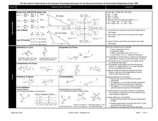
  • 1. The Non-User's Pocket Guide to the Transient Knowledge Necessary for the Structural Divisions of the Architect Registration Exam- ARE CONCEPT COMMENTS Memory Trick: SOHCAHTOA (Indian Tribe)  used when triangle has a 90º angle. Rise (Rise)  SIN RISE Slope  COS RUN  TAN SLOPE Run (Run) a  SIN and COS of any angle are between (+/-) 1 Slope  0º < angle < 45º COS > SIN  45º < angle < 90º SIN > COS Run Rise (Slope) b Law of Sines  Law of Sines and Cosines are used when triangle has no a = = B right angles. Sin A  Law of Sines is used when you are given more angles a than sides.  Law of Cosines is used when you are given more sides C than angles Variations in L.O.A. Properties of a Force:  A Force is defined by four properties: Transmissibility: Force Addition: Forces FORMULAE AND DIAGRAMS Law of Cosines A B Components of a Force: b2 = a2 + c2 - 2ac (Cos B) c2 = a2 + b2 - 2ab (Cos C) Trigonometry/Math or a2 = b2 + c2 - 2bc (Cos A) or or Variations in Sense: Sin C = or Cos C = or Tan C = or c b 90º triangle  Shallower angles (<45º) have larger horizontal components Ø P Px Py OPP HYP ADJ HYP OPP ADJ a b c c a b b Sin B c Sin C c Non- 90º Triangle 1000# = 1 k Ø 2 3 4 1 P Py PX P Py PX Algebraic Method:  For finding the resultant of several forces 3 12  For finding the Resultant of several forces.  Steeper angles (>45º) have larger vertical components A Ø P Py PX C P Py PX Py PX P PX Py P PX Py P Px Py Graphic Method for Force Addition: 1 2 3  Tail of 2 on Head of 1 Tail of 3 on Head of 2 1 23 R  Resultant begins at 1s Tail and ends at last Head 3 12  Tails at same P.O.A. Force Horizontal Vertical 1 +/- +/- 2 +/- +/- 3 +/- +/- R +/- R X = ΣX +/- R y = ΣY 1. Point of Application (P.O.A.) 2. Magnitude ( #,kips ) 3. Sense (Arrowhead, Push or Pull, C or T) 4. Line of Action (L.O.A.) , (Angle with horizontal)  The Equilibrant is also defined as a force that has the same P.O.A., Magnitude and L.O.A. as the Resultant but has an opposite sense (Arrow)  The Resultant is also a force and is thus defined by the four properties listed above.  The Resultant of several forces is a single force that has the same effect on a body as all the other forces combined. P = P P  Algebraic Method for finding the Resultant of several forces is used when force magnitudes and lines of action for each force are known  Algebraic Method of Force Addition 1. Resolve each force into vertical and horizontal components 2. The algebraic (+/-) sum of all horizontal components gives the horizontal component of the Resultant. 3. The algebraic (+/-) sum of all vertical components gives the vertical component of the Resultant  Graphic Method is used when a system is in equilibrium and we need to calculate one or more unknown forces that contribute to equlibrium  Graphic Method for Force Addition 1. Arrange all forces Head to Tail then add (independent of order) 2. Resultant begins with its Tail at the Tail of the 1st Force and Head at the Head of the last 3. Resultant can be determined through calculation P PX Py September, 2004 © 2004 David J. Thaddeus, AIA PAGE : 1 OF 4
  • 2. The Non-User's Pocket Guide to the Transient Knowledge Necessary for the Structural Divisions of the Architect Registration Exam- ARE CONCEPT COMMENTSFORMULAE AND DIAGRAMS Moment Moment = Distance  Summing Moments (∑M = 0) to establish equilibrium  To find Beam / Truss reactions  To maintain equilbrium of members  Overturning Moments due to Wind Loads or Hydrostatic Pressure Couple  Unlike a Moment, a Couple is NOT about a certain point, but rather it is about ANY and ALL points. Moment of a  A Couple depends on Force (P), and perpendicular distance (d) Force X MomentsandCouples Couple= P x d d d between two Forces that make up the couple. MomentsandCouples (clockwise, CW) P  Couple between top Chord (C) and bottom chord (T) in a simply supported truss  Couple between compression in concrete ( top ) and tension in rebar ( bottom ) of reinforced beam 1. ELASTIC RANGE: straight line relationship, slope = E P 2. PLASTIC RANGE: increase in strain, no increase in Load / Stress A 3. STRAIN HARDENING: material deforming in section (necking), and in length ΔL 4. FAILURE: Material is gone! Lo 5. YIELD POINT/ YIELD STRENGTH: material is no longer elastic, deformation is permanent F 6. ULTIMATE STRENGTH: material is about to fail ε Unit Strain ( ΔL/ L0 ) 7. RUPTURE: Kiss it Good-Bye 8. E: Modulus of Elasticity.Measures material's resistance to deformation ΔL = α (ΔT) L0  Shortening or Elongation of members along their axis  Change (Expansion & Contraction) of shape due to Temperature  Examples include Columns, Trusses, Cables, Cross Bracing b = width d = depth c = location of x b Roller: 1 Reaction ( V ) Pin / Hinge: 2 Reactions ( V , H ) Simply Supported:  Statically Determinate (Simply Supported) loading = three unknown reactions, and can be solved using the equation of Static equilibrium.  Statically Indeterminate loading > 3 unknown Reactions Call your engineer. Fixed / Moment: 3 Reactions (V , H , M) Continuous: Multiple Reactions Indeterminate Loading: AE Neutral Axis ΔL= PL0 AxialLoadsGeometry Deflection Shear Bending Moment Area (In2 ) PSI Modulus of Elasticity= Stress / Strain ε: MomentsandCouples Units in / in PSI Stress(F=P/A) Formulas F: Direct Stress Unit Strain E: SupportConditionsStress/Strain bd3 12 Radius of = r = I Gyration A Modulus of Elasticity: E (slope) Fy 8 1 2 3 4 5 6 7 Fu ΔL: deformation, changes in Length (in) caused by Axial Load (P) P : Axial Load (#,k) L0 : Original, undeformed Length (in. not ft.) A : Cross Sectional Area (in2 ) E : Modulus of Elasticity (PSI, KSI) ΔL: Deformation, change in length (in), caused by change in temperature (ºF) ΔT: Change in temperature α : Coefficient of thermal expansion/contraction A = bd  EA36,A-50= 29,000 KSI   P  ΔL   L0  ΔL   A  ΔL   E  ΔL Moment of Inertia (In4 ) Section Modulus (In3 ) V V H V H M (Determinate) 1 2 3 2 1 3 3 3 Force P creates a Negative Moment about point B d A _ + d P B Force P creates a Positive Moment about point A P P ( CCW ) ε Gravity CG ; Center of x Y Y c d/2 d 2 2 3 1  If a Member is inadequate in Shear, increasing the Area (either Width (b) or Depth (d)) is effective.  If a Member is inadequate in Deflection, increasing the Moment of Inertia (Width (b) is OK; but Depth (d) is cubed and) is much more effective in reducing Deflection.  If a Member is inadequate in Bending, increasing the section modulus (width (b) is OK; but Depth (d) is squared and) is much more effective in reducing Bending.  Pin/Hinged connections iclude most wood to wood, bolted steel, and precast concrete connections.  fixed connections include most welded steel / steel connections and cast-in-place concrete. _+CCW CW  A & B are called Centers of Moment, or Centers of Rotation  The perpendicular distance (d) is called the Moment Arm, or Lever Ixx = =Sxx = Ixx bd2 C 6 12 September, 2004 © 2004 David J. Thaddeus, AIA PAGE : 2 OF 4
  • 3. The Non-User's Pocket Guide to the Transient Knowledge Necessary for the Structural Divisions of the Architect Registration Exam- ARE CONCEPT COMMENTSFORMULAE AND DIAGRAMS Example 1:  M = Moment  V =Shear  Equilibruim = ∑ Fx = 0; ∑ Fy = 0; ∑ MAny = 0  Sum of Areas in Shear Diagram = Moment  Magnitude of drop = Concentrated Load  Between concentrated loads, Moment Diagram Slopes  Uniform loads create gradual drop in Shear ( straight line )  Uniform loads create curve (downward cup) in Moment Diagram  Overhangs and cantilevers will always have a negative Moment in Moment Diagram. Simply supported beams always have positive Moments  VMAX always occurs at support Moment is minimum  MMAX occurs where V = 0  Uniform load coefficient, w, = slope in Shear Diagram  Point of Inflection (P.O.I.) is a point on the Moment Diagram where M = 0  Point of Inflection only happens when a beam has an overhang  If Loading Diagram (FBD) is symmetrical, then the Shear Diagram and the Moment Diagram are also symmetrical.  Maximum Shear dictates how much Beam area is needed  Maximum Moment dictates how much Bema Depth is needed  If a hole must be punched out of a Beam to allow for passage of pipe or similar reduction, this must happen at a location of low Shear and low Bending Moment Method of Method of Sections: Joints: Web Stresses Stress increases towards middle Stress increases towards end panels ShearandBendingMomentDiagramsTrusses Top and Bottom Chord Stress  L < R  L = 5' x 12k = 4k Possible Zero Members C  Method of Joints is used to analyze Force / Stress in every member of a Truss  Method of Joints is also used to analyze Force / Stress in a member that is close to a support (not in middle of truss)  Method of Sections is used to analyze only a few (3 max) members of a truss  After cutting a truss in 2 segments, each segment is in Equilibrium ΣF X = 0 ; ΣF Y = 0 ; ΣM ANY = 0  Concentrated Loads in a Truss must be applied at panel points; otherwise we have combined stresses ( T or C + V and M )  Joints that have three or less members framing into them, may potentially have Zero Members 15' 15' + - w , W P Load/ FBD V=0 M=0  R = 10' x12k = 8k 12k 10' 5' 15' L R + 6' 6' 6' 18' 12k 12k L = 21k R = 21k 6'12' 18' 6k R = 4k L = 2k L = 6'/18' x 6k = 2k R = 12'/18' x 6k = 4k C C T T T T T T T T T C C C C C C C C C C C C C C T T T T T C C T  A Truss is inherently stable due to triangulation  Truss is stable in its own plane but needs bridging or cross-bracing perpendicular to its own plane  All joints in an honest Truss are Pinned Joints  Rigid Joints in a Truss will result in less Deflection than Pinned Joints (Advantage)  Rigid Joints in a Truss will result in larger size members than Pinned Joint Trusses since members will have to resist V and M in addition to C or T (Disadvantage)  Members carrying Tension can be much smaller than members carrying Compresion  m + 3 = 2 j ; where m = Number of Members j = Number of Joints Example 2: 6' 6' 6' 18' 12k 18k = w = 1k/ft. W = 18k L = 21k + 2k L = 23 k R = 21k + 4k R = 25 k L = 23k R = 25k September, 2004 © 2004 David J. Thaddeus, AIA PAGE : 3 OF 4
  • 4. The Non-User's Pocket Guide to the Transient Information Needed to Successfully Pass the General Structures Division of the Architect Registration Exam - ARE CONCEPT COMMENTS MATERIAL: DESIGN FOR DESIGN FOR DEFLECTION: Δactual = CONST.x (W or P) (Lx12"/ft.)3 SHEAR: BENDING: E I WOOD BEAMS: STEEL BEAMS: CONCRETE BEAMS: Shear: Shear: Shear: Concrete: f 'c b, d, f 'c Stirrups: f y f y, φ, A v, spacing Bending: Bending Bending Concrete: f'c b, d, f 'c Fb= 24 KSI Rebars: f y (full lateral support) f y, (φ, # rebars), A s WOOD COLUMNS: STEEL COLUMNS: Slenderness: Slenderness: kLUNB. k=0.5 kwood= 0.671 E Columns FORMULAE AND DIAGRAMS BeamsGeneralBeamDesign LUNB./ dLeast I = bd3 / 12 Deflection : F b = MMAX SMIN 5 wL4 Fc W = wL Fv , F b , E LOAD: GEOMETRY: A = bd Shear S = (bd2 ) /6 Bending f v < F v ; V MAX A MIN Fv α L, w, W, P, FBD f b < F b ; F b = MMAX SMIN Δactual < Δallow FV = 3 VMAX 2 A MIN Fb = MMAX Sxx tables LUNB , M-Charts (partial lateral support) wood steel r MMAX = WL / 8 VMAX = W/2 MMAX = PL/4 VMAX = P/2 VMAX = 3P/2 MMAX = PL/2MMAX = PL/3 VMAX = P 23 PL3 ΔMAX = 648 EI 19 PL3 ΔMAX = 348 EI 1 PL3 ΔMAX = 48 EI384 EI 5 WL3 ΔMAX = 384 EI = VMAX, M MAX W = wL W = w L MMAX = WL/8 VMAX = W/2 VMAX = 0.6 W MMAX (+) = 0.08 W L MMAX (-) = - 0.1 W L W/2 AWEB F V = VMAX h A V A S d b SMIN = wL2 / 8 = wL2 /8 Fb< 24 KSI FC , FT , F P A = b x d slenderness ratio 50 L/d 200 KL/r k=1 k=2 b d  Beam design must satisfy Shear, Bending Moment and Deflection requirements  The Allowable Stress (F) of a species of wood or a Grade of steel depends on the material itself and is tabulated in Manuals and Building Codes  The Actual Stress ( f ) is an outcome of the application of a load ( W , P ) on a member  When a Load is applied perpendicular to the axis of a member ( Normal Loading), Shear and Bending stresses develop  The Strain associated with Bending is called Deflection and the deflected shape of a Beam is the inverse (upside/down) of the Moment Diagram  When a load is applied along the axis of a member, Axial Compression and Tension Stresses develop  The strain associated with Tension is Elongation and the strain associated with Compression is Shortening  For the same Magnitude and span, a Uniform Load will cause less Deflection than a Concentrated Load for the same material and geometry  The the same Load and Span, a Cantilever will deflect more than a simply supported beam  For the same Load, Material and Geometry a slight increase in Span will create a huge increase in Deflection  For the same Load and Span, an increase in the Modulus of Elasticity, E, ( a stronger material), will result in less Deflection  For the same Load and Span, an increase in the Moment of Inertia, I , (a deeper member) will result in less deflection  The Points of Inflection on the Moment Diagram of the Continuous beam (Left) indicate the locations of curve reversal, and are the locations where reinforcing steel would be flipped from bottom to top of the beam. L/3 L/3 L/3 P P P PL/3 P P P L/4 L/4 L/4 L/4 PP 3P/2 PL/2 P L/2 L/2 P/2 PL/4 P/2 L w W/2 WL/8 W/2 W/2 w W/2 W/2 WL/8 W/2 w L L L 0.4W 1.1W 1.1W 0.4W 0.6W 0.5W 0.4W 0.4W 0.5W 0.6W d b f A W k11  For all beams; Δactual = CONST.(W or P)(Lx12"/ft.)3 EI  Allowable Deflecion is specified by model codes as a fraction of the span Δallow = L / 240, L / 360,...  FC = P/A  Long and thin ( slender ) columns tend to be governed by buckling  Short and fat ( chunky ) columns tend to be governed by crushing w w - 0.1WL 0.08WL 0.025WL 0.08WL P.O.I.- - +++ - 0.1WL ... . September 2004 © 2004 David J. Thaddeus, AIA PAGE : 4 OF 4