

Recommended
More Related Content
What's hot
What's hot (20)
Similar to Colorimetry B.Sc.III
Similar to Colorimetry B.Sc.III (20)
More from swapnil jadhav
Recently uploaded
Recently uploaded (20)
Colorimetry B.Sc.III
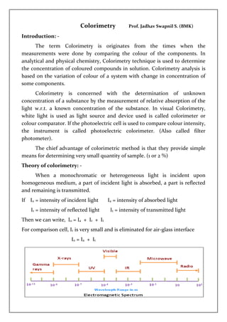
- 1. Colorimetry Prof. Jadhav Swapnil S. (BMK) Introduction: - The term Colorimetry is originates from the times when the measurements were done by comparing the colour of the components. In analytical and physical chemistry, Colorimetry technique is used to determine the concentration of coloured compounds in solution. Colorimetry analysis is based on the variation of colour of a system with change in concentration of some components. Colorimetry is concerned with the determination of unknown concentration of a substance by the measurement of relative absorption of the light w.r.t. a known concentration of the substance. In visual Colorimetry, white light is used as light source and device used is called colorimeter or colour comparator. If the photoelectric cell is used to compare colour intensity, the instrument is called photoelectric colorimeter. (Also called filter photometer). The chief advantage of colorimetric method is that they provide simple means for determining very small quantity of sample. (1 or 2 %) Theory of colorimetry: - When a monochromatic or heterogeneous light is incident upon homogeneous medium, a part of incident light is absorbed, a part is reflected and remaining is transmitted. If I0 = intensity of incident light Ia = intensity of absorbed light Ir = intensity of reflected light It = intensity of transmitted light Then we can write, I0 = Ia + Ir + It For comparison cell, Ir is very small and is eliminated for air-glass interface I0 = Ia + It
- 2. Lambert's Law:- “When a beam of monochromatic light passes through a homogeneous absorbing medium, then the rate of decrease of intensity of the incident light with thickness of absorbing medium is directly proportional to the intensity of the incident radiation.” If, I = intensity of the incident light x = thickness of absorbing medium dI = Small decrease of intensity of the incident radiation w.r.t small thickness dx Then −𝑑𝐼 𝑑𝑥 α I −𝑑𝐼 𝑑𝑥 = K.I 𝑑𝐼 𝐼 = -K .dx ----- (1) K= absorption coefficient. Integrating the eq. (1) between the limits, I =I0 at x = 0 and I = I at x = x we get I = intensity before interring absorbing medium (intensity of incident light) I0 = intensity after interring absorbing medium (intensity of transmitted light) ∫ 𝑑𝐼 𝐼 𝐼 I0 = -K ∫ 𝑑𝑥 𝑥 0 loge 𝐼 𝐼0 = - K. x i.e. 𝐼 𝐼0 = e-k.x I = I0 e-k.x --------- (2) The Lamberts law is usually represented by eq. (2) Lambert - Beer's Law: - “When a beam of monochromatic light passes through a homogeneous absorbing medium, then the rate of decrease of intensity of the incident light with thickness of absorbing medium is directly proportional to the intensity of the incident light as well as to the concentration of solution". If, I = intensity of the incident light x = thickness of absorbing medium C = concentration of solution. dI = Small decrease of intensity of the incident radiation w.r.t small thickness dx Then, −𝒅𝑰 𝒅𝒙 α I.c i.e −𝒅𝑰 𝒅𝒙 = K’.I.c 𝒅𝑰 𝑰 = -K’.c dx --------- (1) K’= molar absorption coefficient.
- 3. Integrating the eq. (1) between the limits, I =I0 at x = 0 and I = I at x = x we get I = intensity before interring absorbing medium (intensity of incident light) I0 = intensity after interring absorbing medium (intensity of transmitted light) ∫ 𝑑𝐼 𝐼 𝐼 I0 = -K’ c ∫ 𝑑𝑥 𝑥 0 loge 𝐼 𝐼0 = - K’c x i.e. 𝐼 𝐼0 = e-k.c.x I = I0 e-k.c.x --------- (2) also, loge 𝐼 𝐼0 = - K’c x i.e. 2.303 log10 = 𝐼 𝐼0 = - K’c x log10 𝐼 𝐼0 = − K’ 2.303 c x i.e. log10 𝐼 𝐼0 = ε c x ( − K’ 2.303 = ε ) i.e. 𝐼 𝐼0 = 10ε.c.x ----- (3) or I = I0 eε.c.x --------- (4) ε = molar extinction coefficient or molar absorptivity or molar absorbance index. Note: - from eq. (3) & (4) Beer’s law may be stated as, “When a beam of monochromatic light passes through a homogeneous absorbing medium, its absorbance remains constant when the concentration(c) and the thickness (x) of absorbing medium are changed in an inverse ratio." Terms used in colorimetry: - 1. Transmittance or transmission (T): - Transmittance is the fraction of incident light transmitted. Or the ratio of intensity of transmitted light to the intensity of incident light is called Transmittance. T = 𝐼 𝐼0 2. Opacity: - The reciprocal of transmittance is called opacity. 𝐼0 𝐼 or 1 𝑇 3. Optical density (D) or Extinction (E) or Absorbance (A): - D = E = A = log 𝐼0 𝐼 = log 1 𝑇 = ε.c.x
- 4. 4. Extinction coefficient (absorbance index) (a): - Extinction coefficient is the optical density for unit path length. Or Extinction coefficient is the reciprocal of thickness (x) required to reduce the light to (1/10th ) of its intensity. a = D/x or I = I0 10-a.x 5. Specific Extinction coefficient (absorbancy index) or (absorptivity)(Es): Specific Extinction coefficient is the optical density per unit path length and unit concentration. Es = D/c.x or I = I0 10-Es.c.x 6. Molar Extinction coefficient (molar absorptivity index) or (absorptivity)(ε): - Molar Extinction coefficient is the Specific Extinction coefficient for unit path length and unit concentration. ε = D/c.x Application of Beer’s law: - 1. C1 & C2 are concentrations of two sample having thickness x1 & x2 respectively and same colour intensity. We can write I1 = I2 => I0 10-ε.c1.x1 = I0 10-ε.c2.x2 i.e. C1 x1 = C2 x2 (system is optically balanced) From this , i) we investigate the validity of Beer’s law by varying C1 & C2. ii) we can determine an unknown concentration C2 comparing with known concentration C1 . 2. When spectrophotometer is used, I/I0 is found directly at known x. By varying x and c verify Lambert’s-Beer’s law and ε may be calculated. Thus unknown concentration cx is calculated as cx = log(𝐼/𝐼0) 𝜀.𝑥 3. Beer’s law is used to determine the concentration of substance in a solution by making use of absorbance of the substance.
- 5. Deviation from Beer’s law: - Beer’s law may not holds good under following condition. i. large amount of electrolyte may affect the absorption and extinction coefficient. ii. Discrepancies are observed when colour solutes dissociates or associates in the solution. iii. Discrepancies are observed when monochromatic light is not used. iv. Discrepancies are observed when temperature is not kept constant. v. when the coloured compounds are kept long time, their colour decomposes and discrepancies are observed. vi. Scattering of light due to particles in the sample. vii. Fluorescence or phosphorescence of the sample. viii. Chemical reactions caused by absorption of light. (E.g. photolysis, dimerization.) ix. Shift in chemical equilibrium and change in PH as a function of concentration. x. Stray light. Classification of methods of colour measurement or comparison: - There are several methods for colour measurement. Standard series method, Duplication method, Dilution method, Balancing method, Photoelectric photometer method, Spectrophotometer method Photoelectric photometer method (single photoelectric colorimeter): Photoelectric colorimeter divided into two classes i.e. one cell and two cell instrument. * One cell photoelectric colorimeter:- Essential parts- i) A light source ii) A light filter iii) A container for the solution. iv) Photocell (Barrier-layer photocell) v) Galvanometer. i) A light source: -
- 6. 2-6 volt lamp operated by battery or A.C. main is used as light source. (sun light, arc light, mercury vapour lamp or discharge tube can also be used.) ii) A light filter: - (monochromator) Monochromator give light of suitable wavelength. It consist of filter or prism. Filter is coloured glass or coloured gelatine coated glass. The best filter is one which gives maximum absorption for given concentration of solution. Now a day’s interference filters are used. These filters are composed of two highly reflecting but partially transmitting films of metal like silver. iii) A container for the solution (Cuvete): - The cells or cuvettes are rectangular or cylindrical vessels with accurate dimensions. For visible light, glass vessels are used. For UV light, quartz vessels are used. iv) A Barrier-layer photocell (photovoltaic or photronic cell): - i. It consists of an iron metal base plate (A) on which a thin layer of selenium (B) is deposited. ii. Selenium layer is covered by a transparent gold metal layer (D) except mechanically strengthened portion (E)called collecting ring. iii. The underside of the metal base plate is covered by a non-oxidizing metal. iv. When light passing through the gold metal layer fall upon the selenium layer. Electrons are released from selenium which penetrates a hypothetical barrier layer (C) giving negative charge to gold metal layer (D). I.e. collecting ring acquires negative polarity while metal base plate acquires positive polarity. Hence this formed cell is connected to a galvanometer.
- 7. v. Photovoltaic cells operate without the use of battery. They are highly sensitive, portable and cheap. They have considerable temperature coefficient. V) Galvanometer: - The response from the photocell is measured b means of galvanometer. * Schematic representation of a single cell photoelectric colorimeter: - Here a light from the source is passes through collimating lens for getting a parallel beam which is then passes through a suitable filter to give a light of particular wavelength. This light is passes through a solvent is received by the photocell which produces a deflection in galvanometer. To determine the unknown concentration, series of reading of standards are taken. These reading are then plotted against concentration and from the graph unknown concentration can be determined.
- 8. B) Spectrophotometer method (single beam direct reading Spectrophotometer): - Essential parts of Spectrophotometer are- i. Light source. ii. Monochromator. iii. Cuvette. iv. Galvanometer. Instrumental Layout: - Working: - 1. The light source is focused on entrance slit (D) by condensing mirror (B) and diagonal mirror (C). 2. The light is then following n prism (F) through collimating mirror (E). 3. Prism (monochromator) divides light into its different wavelength and reflects towards slit (D) through collimating mirror (E). 4. The light with selected wavelength is passed through cuvette (G) and photocell (H), which is connected to meter (M). 5. For visible & near UV region, source is Tungsten-halogen lamp. Far UV region, source is deuterium lamp. In modern instrument prism (F) is replaced by diffraction greeting. Determination of unknown concentration by using concentration- absorption plot: - The response of photocell is measured by micro-ammeter in terms of % absorbance or % transmittance. But for quantitative measurement, % absorbance is more convenient. Hence, we plot a graph of % absorbance vs. concentration and determine the unknown concentration.