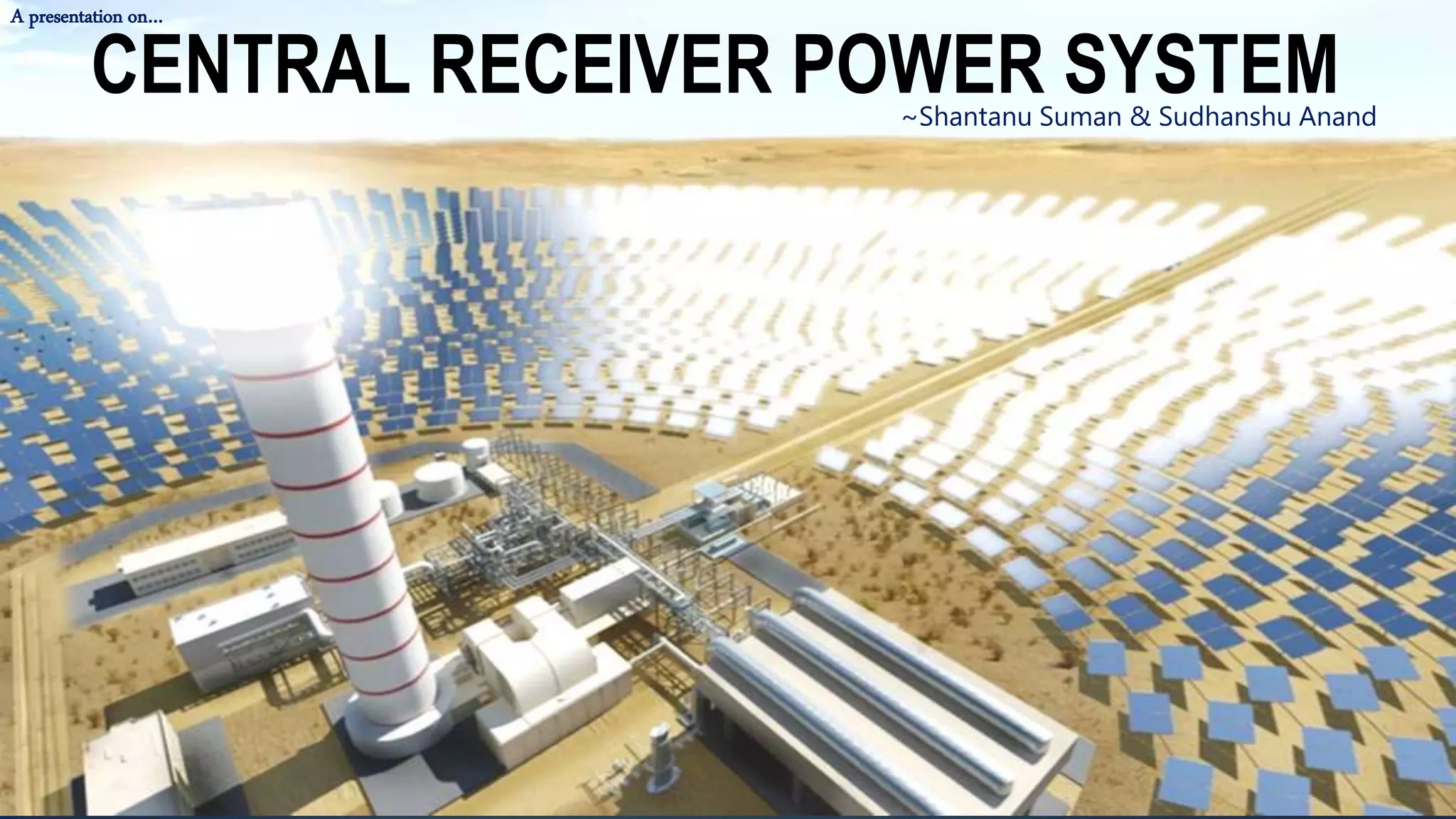
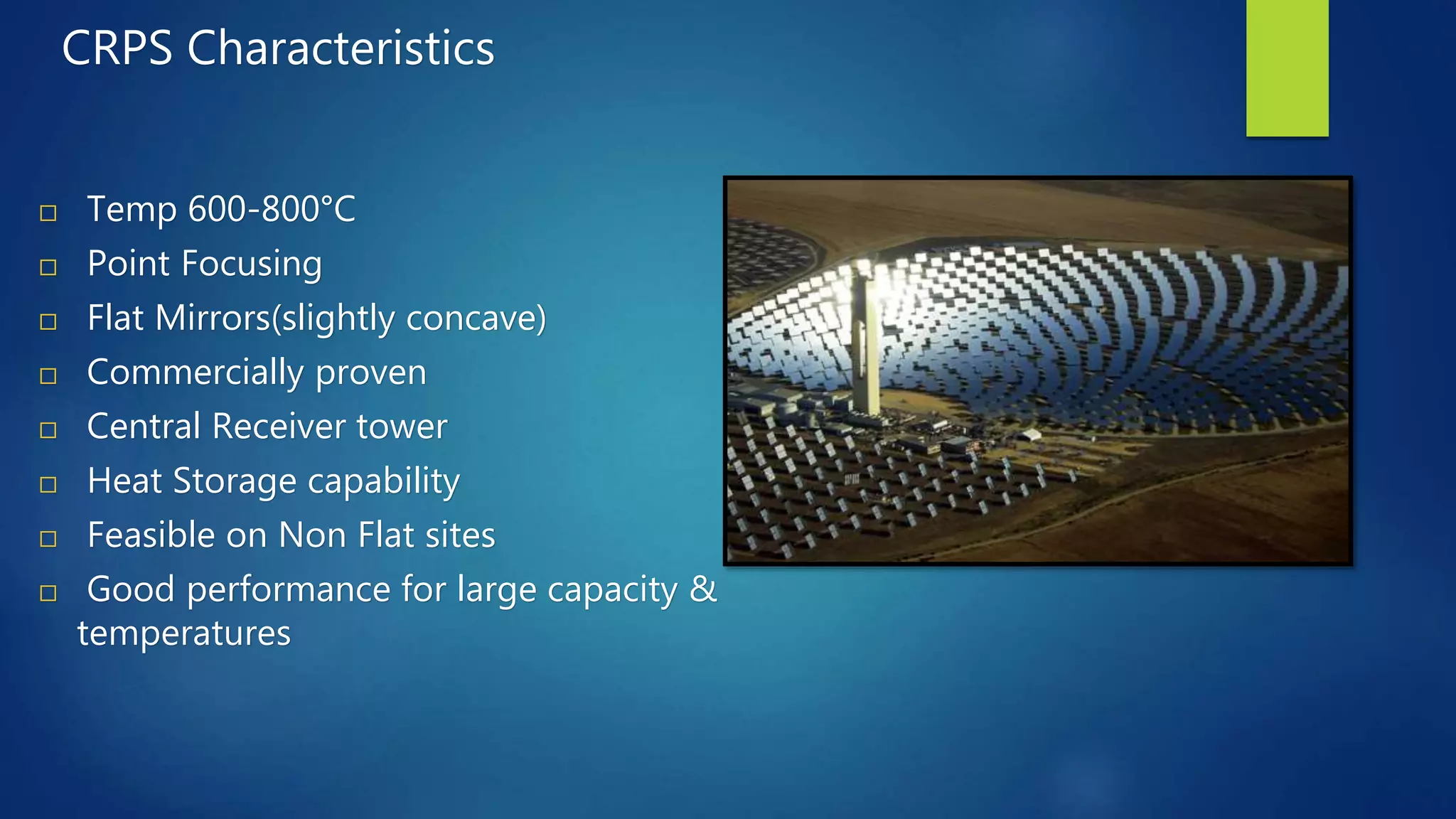
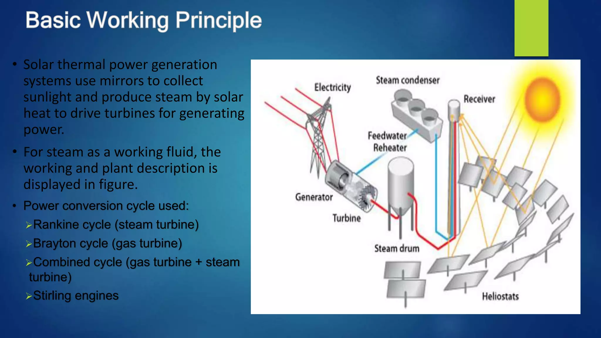
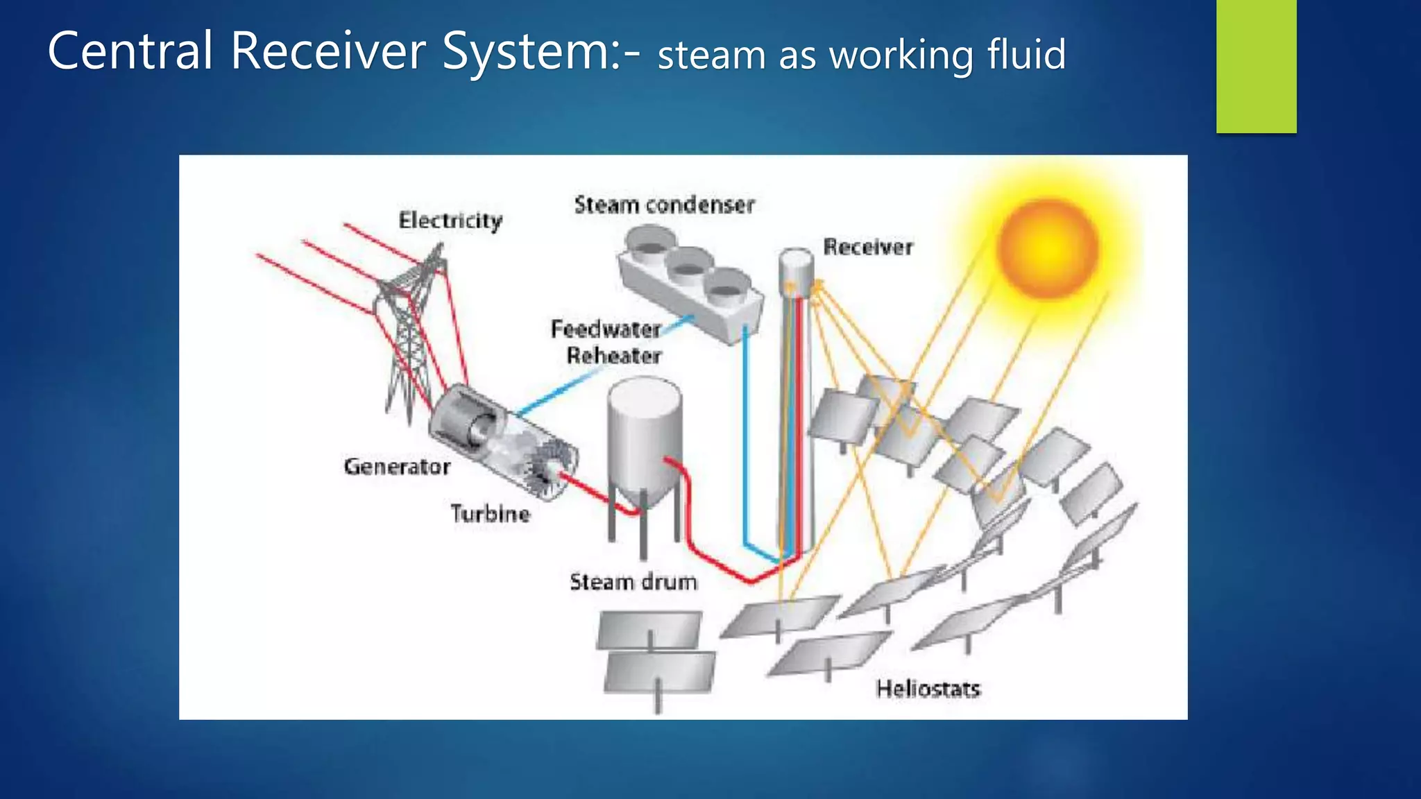
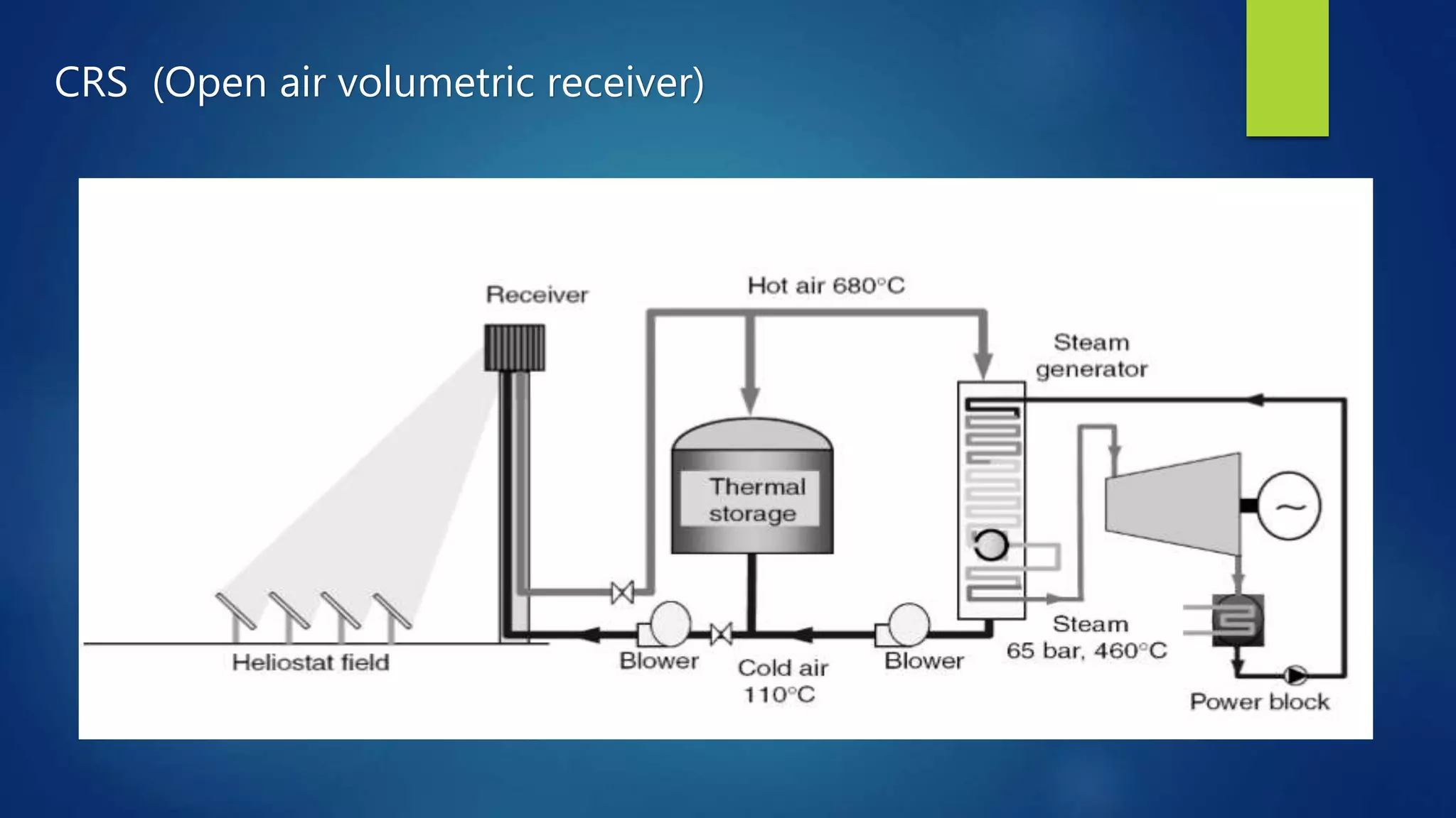
CENTRAL RECEIVER POWER SYSTEM
A presentation on…
~Shantanu Suman & Sudhanshu Anand
Concentrating Solar
Technologies
Low Temperature
(<100°C)
Flat Plate
Collectors
Solar Chimney
Solar Pond
High Temperature-
Point Focusing
(>400°C)
Central Receiver
System
Parabolic Dish
Medium Temperature – Line
Focusing (≈ 400°C)
Parabolic
Trough
Fresnel
Collectors
INTRODUCTION
 Solar thermal power is relatively new technology which has already shown enormous promise and take
the global challenges of clean energy, climate change and sustainable development.
 The CENTRAL RECEIVER concept for solar energy concentration and collection is based on a field of
heliostats that reflect the incident sunshine to a receiver (boiler) at the top of a centrally located tower.
 Solar energy to be collected in the entire field, is transmitted optically to a small central collection region.
 Typically 80-95% of the reflected energy is absorbed into the working fluid
which is pumped up the tower and into the receiver. The heated fluid (or steam) returns down the tower
and then to a thermal demand such as a thermo electrical power plant or an industrial process requiring
heat.
 Central receiver technology for generating electricity has been demonstrated in the Solar One pilot power
plant at Barstow, California. This system consists of 1818 heliostats, each with a reflective area of 39.9
m2(430 ft2) covering 291,000 m2(72 acres) of land. The receiver is located at the top of a 90.8 m (298 ft.)
high tower and produces steam at 516°C (960°F) at a maximum rate of 42 MW.
CRPS Characteristics
 Temp 600-800°C
 Point Focusing
 Flat Mirrors(slightly concave)
 Commercially proven
 Central Receiver tower
 Heat Storage capability
 Feasible on Non Flat sites
 Good performance for large capacity &
temperatures
• Solar thermal power generation
systems use mirrors to collect
sunlight and produce steam by solar
heat to drive turbines for generating
power.
• For steam as a working fluid, the
working and plant description is
displayed in figure.
• Power conversion cycle used:
Rankine cycle (steam turbine)
Brayton cycle (gas turbine)
Combined cycle (gas turbine + steam
turbine)
Stirling engines
SYSTEM DESCRIPTION
The major components of central receiver power
system are:
Heliostat
Tower/ receiver
Working fluid
Storage tanks
Generator
 It is an instrument consisting of mirrors mounted on an axis moved by clockwork by which a sunbeam is
steadily reflected in one direction.
 The thin glass mirrors are supported by a substrate backing to form a slightly concave mirror surface.
 The reflected surface is mounted or supported on a pedestal that permits movement about the azimuth and
elevation axis..
 Another heliostat design concept, not so widely developed, uses a thin reflective plastic membrane
stretched over a hoop.
 Reflectivity of a new, clean mirror ≈ 0.90 - 0.94
CONSIDERATIONS FOR HELIOSTATS:-
1. DESIGN CONSIDERATION (reflectivity, back support structure, elevation drive, azimuth drive, pedestal,
spacing etc.)
2. HELIOSTAT ERRORS (shading and blocking error, cosine efficiency loss)
3. ENVIRONMENTAL CONSIDERATIONS (wind speed, dust on mirror)
4. TRACKING AND POSITIONING
HELIOSTATS
Heliostat
Glass – metal heliostat
Stretched membrane heliostat
Receiver-Tower
Function
The receiver, placed at the top of a tower, is located at a point where reflected energy
from the heliostats can be intercepted most efficiently.
The receiver absorbs the energy being reflected from the heliostat field
and transfers it into a heat transfer fluid.
Components:
• Tower
• Absorber
• Supporting structure
• Other auxiliary elements: steam drum, recirculation pumps…)
Receiver system
 Function
 Components
 Types of receivers
 Working fluids
Types of receiver:
• Cavity receiver:
• External receiver :
(Cylindrical type)
In this receiver flux absorbing surface is
placed inside a insulating cavity to
reduce the convective losses
Geometrical performance of heliostats
Cosine factor
The efficiency depends on both the sun’s position and the location
of the individual heliostat relative to the receiver.
where α and A are the sun’s altitude and azimuth angles, respectively, and z, e, and n
are the orthogonal coordinates from a point on the tower at the height of the
heliostat mirrors.
Yearly average cosine factor for a north heliostat field is 0.71 – 0.91
Shading and blocking
 Shadowing occurs at low sun angles when a heliostat casts its shadow on a heliostat
located behind it. Therefore, not all the incident solar flux is reaching the reflector.
 Blocking occurs when a heliostat in front of another heliostat blocks the reflected flux
on its way to the receiver.
 The amount of shadowing and blocking in a particular field layout is a function of the
heliostat spacing, tower height, and sun angle
Shading
Blocking
Air transmittance
Atmospheric transmittance has been approximated by Vittitoe and Biggs (1978)
for a clear day
for 23 km visibility
where S is the slant range from heliostat to receiver in kilometres
for 5 km visibility
Field losses:-
the energy losses associated specifically with the heliostat field include four and the
five greatest sources of the energy loss.
Followinf are the field losses:
• cosine
• Shadowing and blocking
• Reflectance
• Attenuation – It is third most important loss factor
where ηcos, ηshadow, ηblock, ηrefl and ηatten are efficiencies based
on cosine, shadowing, blocking, mirror reflectance and atmospheric
attenuation respectively.
Receiver losses:-
Following are the receiver loss factor:
• Spillage
• Absorptance
• Radiation
• Convection and conduction
where ηreceiver, ηspill, ηabsor, ηrad, ηconvec, ηcond are efficiencies
based on spillage, absorptance, radiation, convection and
conduction respectively.
CRS
η ≈ 50 – 60 %
Input power
DNI * mirror area
Net thermal output (η ≈ 50 – 60 %)
Efficiency of central receiver power system
Working fluids:
 Good thermal characteristics: thermal capacity, phase-change enthalpy,
state at air temperature
 Non-corrosive, non- Toxic, Non-Flammable
 Inexpensive, abundant
Working fluids for CRS:
Water/Steam
saturated steam
superheated steam
Molten salts
Air
pressurized
atmospheric
Sodium
Thermal oils
Heliostat field
Central Receiver System:- steam as working fluid
CRS (Open air volumetric receiver)
Advantage and Disadvantage of CRS:
Advantages:
• Ability to achieve high temperature
• Renewable. No fuels required.
• Can utilize thermal storage to better match supply with demand
• Operating costs are low
• Multiple thermal energy storage options
• High potential for improved efficiency or cost reduction
Disadvantages:
• Complexity
• Construction/installation costs can be high
• They require a considerable amount of space
• Slightly more expensive than solar PV
• Low energy density
Reference
• https://www.slideshare.net/pritampatel1/finalpresentation4-14140907135606phpapp02?qid=a7736002-88a3-
4e55-adc2-b71e0cf3a149&v=&b=&from_search=22
• https://www.slideshare.net/sustenergy/session-3-point-focus?qid=cbf9b223-69e9-43fb-a576-
b143749c1260&v=&b=&from_search=1
• https://www.slideshare.net/msilvaperez/ecen-5007-lecture-7?qid=a7736002-88a3-4e55-adc2-
b71e0cf3a149&v=&b=&from_search=21
• http://www.powerfromthesun.net/Book/chapter10/chapter10.html
Earth receives around 174 Petawatts of energy from sun and only a
small part of it is sufficient to meet the annual world electricity
consumption of 20 Trillion kWh
We Just need to tap this potential
Thank You

Central receiver power system

  • 1.
    CENTRAL RECEIVER POWERSYSTEM A presentation on… ~Shantanu Suman & Sudhanshu Anand
  • 2.
    Concentrating Solar Technologies Low Temperature (<100°C) FlatPlate Collectors Solar Chimney Solar Pond High Temperature- Point Focusing (>400°C) Central Receiver System Parabolic Dish Medium Temperature – Line Focusing (≈ 400°C) Parabolic Trough Fresnel Collectors
  • 3.
    INTRODUCTION  Solar thermalpower is relatively new technology which has already shown enormous promise and take the global challenges of clean energy, climate change and sustainable development.  The CENTRAL RECEIVER concept for solar energy concentration and collection is based on a field of heliostats that reflect the incident sunshine to a receiver (boiler) at the top of a centrally located tower.  Solar energy to be collected in the entire field, is transmitted optically to a small central collection region.  Typically 80-95% of the reflected energy is absorbed into the working fluid which is pumped up the tower and into the receiver. The heated fluid (or steam) returns down the tower and then to a thermal demand such as a thermo electrical power plant or an industrial process requiring heat.  Central receiver technology for generating electricity has been demonstrated in the Solar One pilot power plant at Barstow, California. This system consists of 1818 heliostats, each with a reflective area of 39.9 m2(430 ft2) covering 291,000 m2(72 acres) of land. The receiver is located at the top of a 90.8 m (298 ft.) high tower and produces steam at 516°C (960°F) at a maximum rate of 42 MW.
  • 4.
    CRPS Characteristics  Temp600-800°C  Point Focusing  Flat Mirrors(slightly concave)  Commercially proven  Central Receiver tower  Heat Storage capability  Feasible on Non Flat sites  Good performance for large capacity & temperatures
  • 5.
    • Solar thermalpower generation systems use mirrors to collect sunlight and produce steam by solar heat to drive turbines for generating power. • For steam as a working fluid, the working and plant description is displayed in figure. • Power conversion cycle used: Rankine cycle (steam turbine) Brayton cycle (gas turbine) Combined cycle (gas turbine + steam turbine) Stirling engines
  • 6.
    SYSTEM DESCRIPTION The majorcomponents of central receiver power system are: Heliostat Tower/ receiver Working fluid Storage tanks Generator
  • 7.
     It isan instrument consisting of mirrors mounted on an axis moved by clockwork by which a sunbeam is steadily reflected in one direction.  The thin glass mirrors are supported by a substrate backing to form a slightly concave mirror surface.  The reflected surface is mounted or supported on a pedestal that permits movement about the azimuth and elevation axis..  Another heliostat design concept, not so widely developed, uses a thin reflective plastic membrane stretched over a hoop.  Reflectivity of a new, clean mirror ≈ 0.90 - 0.94 CONSIDERATIONS FOR HELIOSTATS:- 1. DESIGN CONSIDERATION (reflectivity, back support structure, elevation drive, azimuth drive, pedestal, spacing etc.) 2. HELIOSTAT ERRORS (shading and blocking error, cosine efficiency loss) 3. ENVIRONMENTAL CONSIDERATIONS (wind speed, dust on mirror) 4. TRACKING AND POSITIONING HELIOSTATS
  • 8.
  • 9.
    Glass – metalheliostat Stretched membrane heliostat
  • 10.
    Receiver-Tower Function The receiver, placedat the top of a tower, is located at a point where reflected energy from the heliostats can be intercepted most efficiently. The receiver absorbs the energy being reflected from the heliostat field and transfers it into a heat transfer fluid. Components: • Tower • Absorber • Supporting structure • Other auxiliary elements: steam drum, recirculation pumps…) Receiver system  Function  Components  Types of receivers  Working fluids
  • 11.
    Types of receiver: •Cavity receiver: • External receiver : (Cylindrical type) In this receiver flux absorbing surface is placed inside a insulating cavity to reduce the convective losses
  • 12.
  • 13.
    Cosine factor The efficiencydepends on both the sun’s position and the location of the individual heliostat relative to the receiver. where α and A are the sun’s altitude and azimuth angles, respectively, and z, e, and n are the orthogonal coordinates from a point on the tower at the height of the heliostat mirrors. Yearly average cosine factor for a north heliostat field is 0.71 – 0.91
  • 14.
    Shading and blocking Shadowing occurs at low sun angles when a heliostat casts its shadow on a heliostat located behind it. Therefore, not all the incident solar flux is reaching the reflector.  Blocking occurs when a heliostat in front of another heliostat blocks the reflected flux on its way to the receiver.  The amount of shadowing and blocking in a particular field layout is a function of the heliostat spacing, tower height, and sun angle Shading Blocking
  • 15.
    Air transmittance Atmospheric transmittancehas been approximated by Vittitoe and Biggs (1978) for a clear day for 23 km visibility where S is the slant range from heliostat to receiver in kilometres for 5 km visibility
  • 16.
    Field losses:- the energylosses associated specifically with the heliostat field include four and the five greatest sources of the energy loss. Followinf are the field losses: • cosine • Shadowing and blocking • Reflectance • Attenuation – It is third most important loss factor where ηcos, ηshadow, ηblock, ηrefl and ηatten are efficiencies based on cosine, shadowing, blocking, mirror reflectance and atmospheric attenuation respectively.
  • 17.
    Receiver losses:- Following arethe receiver loss factor: • Spillage • Absorptance • Radiation • Convection and conduction where ηreceiver, ηspill, ηabsor, ηrad, ηconvec, ηcond are efficiencies based on spillage, absorptance, radiation, convection and conduction respectively.
  • 18.
    CRS η ≈ 50– 60 % Input power DNI * mirror area Net thermal output (η ≈ 50 – 60 %) Efficiency of central receiver power system
  • 19.
    Working fluids:  Goodthermal characteristics: thermal capacity, phase-change enthalpy, state at air temperature  Non-corrosive, non- Toxic, Non-Flammable  Inexpensive, abundant Working fluids for CRS: Water/Steam saturated steam superheated steam Molten salts Air pressurized atmospheric Sodium Thermal oils
  • 20.
  • 21.
    Central Receiver System:-steam as working fluid
  • 22.
    CRS (Open airvolumetric receiver)
  • 23.
    Advantage and Disadvantageof CRS: Advantages: • Ability to achieve high temperature • Renewable. No fuels required. • Can utilize thermal storage to better match supply with demand • Operating costs are low • Multiple thermal energy storage options • High potential for improved efficiency or cost reduction Disadvantages: • Complexity • Construction/installation costs can be high • They require a considerable amount of space • Slightly more expensive than solar PV • Low energy density
  • 24.
  • 25.
    Earth receives around174 Petawatts of energy from sun and only a small part of it is sufficient to meet the annual world electricity consumption of 20 Trillion kWh We Just need to tap this potential Thank You