1. * GB780191 (A)
Description: GB780191 (A) ? 1957-07-31
Improvements in or relating to control devices for fluid supply systems
Description of GB780191 (A)
We, POWER JETS (RESEARCHAND DEVELOP-
MENT LIMITED, a British Company, of 25 Green Street, London, W.1, do
hereby declare the invention, for which we pray that a patent may be
granted to us, and the method by which it is to be performed, to be
particularly described in and by the following
statement:-
The invention relates to control devices for fluid supply systems.
An object of the invention is to provide a device permitting the
control of the rate of flow of a fluid supply to be effected by either
of two adjustments.
Another object of the invention is to provide a device permitting the
control of the rate of flow of each of several fluid supplies either
by individual or collective adjustment, the collective adjustment
being such that the ratio of the rate of flow of one supply to the
rate of flow of another, as determined by their individual
adjustments, is maintained.
The fulfilment of these objects is desirable, for example, in a liquid
fuel system employing a number of fuel nozzles in which it is required
firstly that the rates of discharge of any two nozzles may be adjusted
to a particular relationship and secondly that the total rate of
discharge of all the nozzles may be varied while preserving that
relationship.
The invention provides a control device for a fluid system having a
number of fluid supplies and for each supply a metering orifice
defined by two pairs of parallel boundary walls, a first control means
for varying the width of the orifice by effecting relative movement
between the walls of one pair towards or away from each other without
varying the length of the orifice, and a second control means for
varying the length of the orifice by effecting relative movement
between the walls of the other pair towards or away from each other
2. without varying the width of the orifice wherein the first or second
control means for the respective supplies are interconnected for
simultaneous operation.
The invention will be understood from the following description with
reference to the drawings accompanying the Provisional Specification
of three constructional embodiments of the invention shown
respectively in Figures 1 and 2, 3 and 4 and 5 and 6, of the drawings.
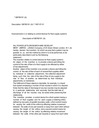
Figure 1 is an isometric view of a liquid fuel system in which a pump
1 supplies fuel through a manifold 2 to each of a number (in this case
three) of metering devices 3 contained in a common cylinder block 4.
Each metering device controls the flow in a manner to be described
through a discharge pipe 5 to one of a number of fuel nozzles (not
shown). Figure 2 of the drawing shows to a larger scale an axial
cross-section through one metering device. Each device consists of a
hollow liner 6 which engages a complementary bore in the cylinder
block 4 and is located by the plug 7. The liner is closed at one end
and has an integral shaft 8 extending outside the cylinder block by
which the liner 6 is rotatable in the block.
The bore of the liner 6 houses a hollow piston 9 which is closed at
one end and has an integral shaft 10. The shaft 10 extends through a
hollow boss 11 on the cylinder block and is secured to a handwheel 12
which is in threaded engagement with the boss 11.
The attachment between the handwheel 12 and piston shaft 10, by the
bolt 13, is such that rotation of the handwheel merely moves the
piston axially without rotation of the 780,191 PATENT SPECIFICATION
Inventor: -CHARLES LONG.
Date of filing Complete Specification: March 25, 1955.
Application Date: March 26, 1954. No. 8892/54.
Complete Specification Published: July 31, 1957.
Intex at Acceptanee:-Class 135, VE(1Y: 5B), VlW3(B: X).
International Classification:-FO6k.
COMPLETE SPECIFICATION.
Improvements in or relating to Control Devices for Fluid Supply
Systems.
piston which is precluded by the pin 14 in the shaft 10 engaging an
axial slot 15 in the boss. The exposed end of the pin 14 affords an
indication of the axial position of the piston 9. The cylinder block 4
is provided with a supply annulus 16 and a discharge annulus 17,
encircling the liner 6 and in communication with respectively the
supply manifold 2 and the discharge pipe 5. The liner 6 is provided
with inlet ports 18 affording communication between the supply annulus
16 and the bores of the liner 6 and piston 9. Communications between
the bore of the piston 9 and the discharge annulas 17 is afforded by
two rectangular ports 19 and 20 in respectively the piston 9 and liner
3. 6 which co-operate to define a metering orifice. The arrangement is
such that rotation of the liner 6 will vary the circumferential
dimension of the metering orifice, while axial movement of the piston
9 will vary the axial dimension of the orifice.
A. manually operated regulating lever 21 is attached to the shaft 8 of
the liner 6 and is connected-by the pin-jointed link 22 to the
corresponding regulating levers of the several metering devices, each
of which is similar to that described. Thus rotational movements of
the several liners 6 of the metering devices are collectively
controlled by the regulator 21. Accordingly, whatever relationship
exists between the areas of the several metering orifices as
determined by the individual settings of their indicators 14, this
relationship will be preserved throughout any adjustment of the
regulator 21. Thus, the flow through any two discharge pipes 5 having
been adjusted by the associated handwheels 12 in a given ratio, this
ratio will be preserved when the total flow through the two pipes 5 is
varied by the regulator 21.
The fluid supply system shown in Figures 3 and 4, is generally similar
to that shown in Figures 1 and 2, to which latter Figures 3 and 4
respectively correspond. It differs, however, in that in each metering
device, the liner 6 is not rotatable in the cylinder block 4 while the
piston 9 is adapted not only for axial displacement by rotation of the
handwheel 12 but also for rotational movement according to the
adjustment of an alternative regulator 23. Thus in each metering
device the piston shaft 10 -is provided with an axially extending
keyway 24. The boss 11 of the cylinder block 4 is provided with a slot
25 extending partly round its circumference. The regulator 23 is
entered into the slot 25 and embraces the shaft 10, being provided
with a projection 26 complementary to and engaging the keyway 24. Thus
circumferential movement of the regulator 23 serves to rotate the
piston whatever the axial position of the latter. The indication
afforded by the pin 14 of the previously described embodiment is given
in the embodiment now described by the shroud 121 of the handwheel 12.
The plug 5 secures the liner 6 in the cylinder block and encloses the
end of the liner. The regulators 23 of the several metering devices
are again connected by a pin-jointed link 22. Thus the system
functions in accordance with the individual settings of the handwheel
and the common setting of the regulator 23 in a similar manner to the
previously described 75 embodiment.
Figures 5 and 6 of the drawings show respectively a cross-sectional
elevation and plan of a valve which controls the flow of two liquid
fuel supplies. The valve body 80 27 houses a cylindrical liner 28
which is located in the body by a cover 29 secured by the countersunk
screw 30 to the body.
4. The bore of the liner accommodates a hollow piston 31 which is closed
at its upper end 8:5 and has an integral shaft 32 passing through the
cover 29. A flange 33 is secured by the nuts 34 for rotation about a
boss 35 on the cover and carries two pillars 36 supporting a yoke 37.
A handwheel 38 is so mounted 90 on the yoke as to be freely rotatable
with respect thereto. An internally threaded sleeve 39 integral with
the handwheel embraces the complementary threaded end 40 of the piston
shaft 32. Integral with the 95 shaft 32 is a guide plate 41 which
engages the pillars 36 to ensure rotation of the piston with the
flange 33. A regulating lever 42 is attached to the flange whereby the
latter may be manually rotated. The arrangement 100 is such that
adjustments of the handwheel 38 and regulator 42 result respectively
in axial and rotational movement of the piston 31. The valve body 27
is provided with a fuel inlet port 43 communicating with the 105 bore
of the piston 31, and with two fuel outlet ports 44 and 45 each
communicating with one of two discharge annuli 46 and 47 encircling
the liner 28. The liner 28 is provided with two rectangular ports 48
and 49 110 communicating one with each discharge annulus and the
piston 31 has two rectangular ports 50 and 51 co-acting with the liner
ports 48 and 49 respectively. Whereas the piston ports 50 and 51 are
axially aligned, 115 the liner ports 48 and 49 have one side only
axially aligned and extend circumferentially respectively in opposite
directions from their aligned sides. The two pairs of ports 48, and
49, 51 serve to define two metering 120 orifices for two separate fuel
supplies whose axial dimension is simultaneously varied upon axial
movement of the piston. The circumferential dimensions of the two
orifices are related in so far as rotation of 125 the piston increases
one and diminishes the other by a similar amount. Thus it is possible
to adjust the regulator 42 to obtain any ratio of the areas of the two
metering orifices, while leavin2 their combined area 130 780,191 7. A
fluid system having a number of
* Sitemap
* Accessibility
* Legal notice
* Terms of use
* Last updated: 08.04.2015
* Worldwide Database
* 5.8.23.4; 93p