1. 2009
THAI-ASIA P.E. PIPE CO., LTD.
BUTT-FUSION WELDING GUIDELINE
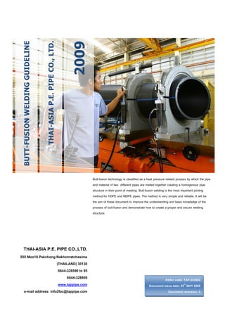
Butt-fusion technology is classified as a heat pressure related process by which the pipe
end material of two different pipes are melted together creating a homogenous pipe
structure in their point of meeting. Butt-fusion welding is the most important jointing
method for HDPE and MDPE pipes. The method is very simple and reliable. It will be
the aim of these document to improve the understanding and basic knowledge of the
process of butt-fusion and demonstrate how to create a proper and secure welding
structure.
THAI-ASIA P.E. PIPE CO.,LTD.
555 Moo18 Pakchong Nakhonratchasima
(THAILAND) 30130
6644-328590 to 95
6644-328600
www.tappipe.com
e-mail address: info2fac@tappipe.com
Editor code: TAP-352802
Document issue date: 25th MAY 2009
Document reversion: 2
2. TECHNICAL INFORMATION
BUTT-FUSION WELDING OF POLYETHYLENE PIPE
Quality Management Systems
Q001
Cert. No. NQ767/04
005
Cert. No. TH04/0500
Welding Guideline
Content
1.
2.
3.
4.
5.
6.
Scope
General Requirement
Welding Machine
Welding Parameter
Welding Cycle Calculation (in case of welding operation by manual machine)
Welding Operation
Appendix – A – The welding guideline time values of welding operation for High Density
Polyethylene Pipe.
Appendix – B – The sample of welding protocol form for welding data record.
3
3
4
6
9
12
16
22
Page 2 of 22
TAP-352802-TEC-BUTT WELDING-52R2
th
Issue Date 25 MAY 2009
Normative Reference
1. Direction DVS 2207-1:1995 “Welding of thermoplastics” Heated tool welding of pipe,
pipeline components and sheet made from PE-HD, page 1 to 4, 6 and 9.
2. Borealis A/S, Polyethylene ART 339 03.04.1998 Ed.1 “Welding of large diameter PE pipe”,
page 6.
3. TECHNICAL INFORMATION
BUTT-FUSION WELDING OF POLYETHYLENE PIPE
Quality Management Systems
Q001
Cert. No. NQ767/04
005
Cert. No. TH04/0500
Welding Guideline
1. Scope
Butt-fusion technology is classified as a heat pressure related process by which the pipe end material of two
different pipes are melted together creating a homogenous pipe structure in their point of meeting.
When Thermoplastics material like high density polyethylene (HDPE), medium density polyethylene (MDPE) are
heated up to a temperature between 200C to 220C the material will change from a solid to a liquid state under
the application of a certain pressure. With regard to the following instructions, suitability within the melt flow rates
MFR 190/5 0.3 g to 1.7 g/10 min may be assumed. When two properly cut and heat-softened pipe ends are
brought together and held under pressure, they are fuse together, forming a homogenous and tight joint when
cooled.
Simply in idea and performance, the butt-fusion process demands a high grade of accuracy to give the final
product, i.e. the butt weld, a level of quality equal to that of the pipe itself. It will be the aim of these document to
improve the understanding and basic knowledge of the process of butt-fusion and demonstrate how to create a
proper and secure welding structure.
2. General Requirement
The quality of welding joints depends on the qualification of the welder, the suitability of the used equipment and
devices as well as on observance to the welding standards. The welding joint can be tested by means of nondestructive and/or destructive methods. Every welder has to be trained and has to be in possession of a valid
qualification certificate. The intended application range may be decisive of the kind of qualification.
The welding zone must be protected against bad weather influences (e.g. moisture and temperatures below +5
C). If it is ensured by suitable measures (e.g. preheating, tent, heating) that the condition are suitable for
welding work may be carried out at any outside temperature insofar as the welder is not hindered in his handling.
If necessary, an additional proof must be provided by carrying out sample welds under the mentioned condition.
If the semi-finished product is heated up unevenly under influence of sunshine, the temperature compensation in
Page 3 of 22
TAP-352802-TEC-BUTT WELDING-52R2
th
Issue Date 25 MAY 2009
Butt-fusion welding is the most important jointing method for HDPE and MDPE pipes. The method is very simple
and reliable. The principal procedure is following:
The two pipes are clamped in a welding machine having a hydraulic system for the movable half of the
machine and for the pressure build up.
The pipe ends are squared by a special cutter, trimmer or facing tool.
An electrically heated metal plate is placed between the pipe ends.
The pipe ends are pressured against the hot plate with a specified pressure and for a specified time.
When the ends have melted, the hot plate is taken out and the melted ends are pressed against each
other to make a butt weld. The welding pressure is specified, and the welding time as well.
When the weld has been cooled down, the pipes are taken out from the machine and preparation of the
next joint can start.
4. TECHNICAL INFORMATION
BUTT-FUSION WELDING OF POLYETHYLENE PIPE
Quality Management Systems
Q001
Cert. No. NQ767/04
005
Cert. No. TH04/0500
Welding Guideline
the area of the welding joint can be reached by covering. A cooling down during the welding process by
ventilation has to be avoided, e.g. by closing the pipe-ends during welding.
Pipe from coils are oval immediately after uncoiling. The pipe end must be prepared before welding, e.g. by
careful heating up with a hot-air equipment and use of a suitable clamping and/or re-rounding device. The
connection zones of the components to be welded must be undamaged and have to be free of contamination
(e.g. dirt, oil, shavings).
The welding work must be monitored. Kind and range of supervising has to be agreed between the contract
partners, this is recommended to record the welding data in welding protocols (sample see appendix B) or on
data comers. Within the frame of the quality assurance it is recommended to perform and test samples of joints
before beginning and during the welding works.
The welding machine is major equipment that necessary
for qualify welder used to perform the butt-fusion welding
process. The good quality and reliable machine would be
consideration to use created a proper and secure welding
structure. There are many suppliers welding machine in
the global market and there are variety model that can be
selection depend on the application or installation project
requirement. Generally standard welding machine there
are the basic machine function and the option up on request such as a welding data record or the data logger,
the CNC control unit for full automatic welding machine etc. The standard welding machine component as show
on the figure1 and their basic work function are shown on as the following detail:
1. The machine base structure had a dual clamping device with quick action lock guide by two hydraulic
cylinders two flexible hoses with quick-action coupling connect the appliance to the hydraulic control.
2. The hydraulic control unit which is control moving the right dual clamping device and precisely
controls the jointing force, motor- pump start auto lock pressure by pilot check valve and accumulator.
3. The facing tool or trimmer is attached to the tooling support frame. It is electrically power by a chain or
gear drive protected by an all-enclosing aluminum case and automatically delivers chips to the outside.
4. The heater element, there is a teflon coating on the surface plate which is attached to the tooling
support frame. There is temperature sensor PT-100 or PT-1000 and digital control equipped with control
lamps an ON/OFF switch and extension cable with earthling-contact plug.
5. The clamping inserts consisting of eight haft shells per dimension are available for cover all the range
of pipe diameter that is the machine capable to welding such as the welding machine model 315, there
are the clamp insert for pipe size 90,110,125,140,160,180,200,225,250 and 280 mm.
6. The carrier case or tooling support frame is for heater element and the facing tool.
7. The stub end and concentric reducer holder is for locking the center position for weld with pipe end.
Page 4 of 22
TAP-352802-TEC-BUTT WELDING-52R2
th
Issue Date 25 MAY 2009
3. Welding Machine
5. TECHNICAL INFORMATION
BUTT-FUSION WELDING OF POLYETHYLENE PIPE
Quality Management Systems
Q001
Cert. No. NQ767/04
005
Cert. No. TH04/0500
Welding Guideline
Heating Plate
Facing Tool
Electric Control Box
Hydraulic Control
Unit
1. Machine Base
Structure
2. Tool Support
Frame
4. Heating Plate
5. Hydraulic Control
Unit
Figure1. Standard Welding Machine Component (basic machine function)
Page 5 of 22
TAP-352802-TEC-BUTT WELDING-52R2
th
Issue Date 25 MAY 2009
3. Trimmer or Facing Tool
6. TECHNICAL INFORMATION
BUTT-FUSION WELDING OF POLYETHYLENE PIPE
Quality Management Systems
Q001
Cert. No. NQ767/04
005
Cert. No. TH04/0500
Welding Guideline
4. Welding Parameter
The control parameter of welding cycle was shown on the figure2. They are reference to DVS 2207-1:1995 and
NEN 7200 (VEG-85) the international welding standard. In cases of used the calculation method or/and
recommended values from the standard.
Pressure
(bar)
P1
P3
P2
T1
T2
T3
T4
T5
Time
(minute or second)
Table1. Welding Parameter and control for calculation method and recommended values to be used
Description
Parameter
Calculation
Recommended
Values
0
1. Heating temperature
200 - 220 C
Figure3.
2
_
2. Alignment pressure
(bar) (P1) 0.15 ± 0.01 N/mm A1 / A2 x 1.5
3. Alignment time (Bead Created)
(T1) Until bead created Until bead created
Table3.
follow item 4
follow item 4
4. Bead height
(mm.)
0.5 + (0.1 x e)
0.5 + (0.1 x e)
5. Heating-up pressure
(bar) (P2) ≤ 0.02 N/mm2
A1 / A2 x 0.2
6. Heating-up time
(sec.) (T2) 10 x e
10 x e
Table3.
7. Changeover time
(sec.) (T3) 3 + (0.01 x OD)
3 + (0.01 x OD)
Table3.
8. Joining pressure built-up time (sec.) (T4) 3 + (0.03 x OD)
3 + (0.03 x OD)
Table3.
2
9. Joining pressure
(bar) (P3) 0.15±0.01 N/mm
A1 / A2 x 1.5
10. Minimum cooling time
(min.) (T5) 3 + e
3+e
Table3.
11. Minimum bead width
(mm.)
3 + (0.50 x e)
3 + (0.50 x e)
12. Maximum bead width
(mm.)
5 + (0.75 x e)
5 + (0.75 x e)
Remarks: OD = Outside Diameter (mm.), e = Wall Thickness (mm.)
A1 = Pipe section area (mm2) by calculation formula: [(OD2– ID2)/4]
A2 = Hydraulic cylinder section area (mm2) by calculation formula: [(Number of hydraulic cylinder) x (iD2Cylinder– OD2Shaft)/4]
Page 6 of 22
TAP-352802-TEC-BUTT WELDING-52R2
th
Issue Date 25 MAY 2009
Figure2. Process stages of butt-fusion welding relation between pressure and time
7. TECHNICAL INFORMATION
BUTT-FUSION WELDING OF POLYETHYLENE PIPE
Quality Management Systems
Q001
Cert. No. NQ767/04
005
Cert. No. TH04/0500
Welding Guideline
Alignment of pipe and gap width
The joining areas have to be plane with a clean and grease-free tool directly before the welding, so they are
plane-parallel in clamped condition. The gap width and the misalignment have to be controlled. The
misalignment of the joining areas on the pipe outside respect may not pass the permissible value of 0.1 x wall
thickness of pipe. The permissible gap width under alignment pressure is show on Table2.
Table2. The maximum gap width is allowance between the treated welding zones.
Pipe outside diameter range
Gap width
(mm.)
(mm.)
< 355
0.5
400…< 630
1.0
630…< 800
1.3
800…< 1000
13
> 1000
2.0
The treated welding areas should be neither dirtied nor touched by hand, as a retreatment would be necessary
then. Shavings fallen into the pipe have to be remove.
Welding temperature
Figure3. Recommended values for the heating tool temperatures subject to wall thickness
Page 7 of 22
TAP-352802-TEC-BUTT WELDING-52R2
th
Issue Date 25 MAY 2009
The heating tool temperature is 200 to 220 C. In principle the upper temperature limit is aspired for smaller
pipe wall thicknesses, the lower temperature limit for bigger ones. The recommended value is show on figure3.
8. TECHNICAL INFORMATION
BUTT-FUSION WELDING OF POLYETHYLENE PIPE
Quality Management Systems
Q001
Cert. No. NQ767/04
005
Cert. No. TH04/0500
Welding Guideline
The control or inspection measurement must be done within the welding area on the heating tool which
corresponds to the semi-finished product. For adjusting the temperature balance, the heated tool may be inserted
10 minutes after reaching the set temperature at the earliest, before start the welding process.
Table3. Recommended values for the heating tool butt-fusion welding of pipes and fittings from HDPE, at
an ambient temperature of approximately 20 C and moderate air flow ( Interim values have to be
interpolated).
(mm)
≤ 4.5
4.5… 7
7 … 12
12 … 19
19 …26
26 … 37
37 … 50
50 … 70
2
Alignment
3
Heating-up (T2)
Bead height on heating
tool at the end of the
alignment time (alignment
with 0.15 N/mm²)
Heating-up time
=10 x wall thickness
(heating-up with
< 0.02 N/mm²)
(mm)
minimum values
(second)
0.5
1.0
1.5
2.0
2.5
3.0
3.5
4.0
4
Changeover (T3)
5
Joining
(T4)
Joining
Pressure
build-up
time
(second)
maximum time
45
45…70
70…120
120…190
190…260
260…370
370…500
500…700
Page 8 of 22
5
5…6
6…8
8…10
10…12
12…16
16…20
20…25
(T5)
Cooling time under
joining pressure
P=0.15 N/ mm² + 0.01
(second)
(minute) minimum
values
6
6…10
10…16
16…24
24…32
32…45
45…60
60…80
5
5…6
6…8
8…11
11…14
14…19
19…25
25…35
TAP-352802-TEC-BUTT WELDING-52R2
th
Issue Date 25 MAY 2009
1
Nominal
wall
Thickness
9. TECHNICAL INFORMATION
BUTT-FUSION WELDING OF POLYETHYLENE PIPE
Quality Management Systems
Q001
Cert. No. NQ767/04
005
Cert. No. TH04/0500
Welding Guideline
5. Welding Cycle Calculation (in case of welding operation by manual machine)
Pressure Calculation for the welding machine
Welding Pressure
P (Cylinder) = P (Pipe) x (A1/A2) …………………………. [exclude drag force]
A1 = HDPE Pipe section area ………………. (mm2)
A2 = Hydraulic cylinder section area ……….. (mm2)
P (Pipe) = 0.15 N/mm2 or 1.5 ……………………… (bar) [for P1 and P3]
= ≤ 0.02 N/mm2 or 0.2 …………………… (bar) [for P2]
P (Cylinder) = Operating pressure of welding machine (bar.)
1) Calculation for HDPE Pipe section area: A1 = (OD2-ID2) / 4 (mm2)
Case1. HDPE pipe 315 mm. wall thickness 15.0 mm. PN 6.3 SDR 21
A1 = 3.142x(3152-(315-(2x15))2) / 4
= 14,139.00 mm2
Case2. HDPE pipe 400 mm. wall thickness 19.1 mm. PN 6.3 SDR 21
A1 = 3.142x(4002-(400-(2x19.1))2) / 4
= 22,858.64 mm2
2) Calculation for Hydraulic cylinder effective area of welding machine
Hydraulic cylinder effective area: A2 = No. of cylinder x (ID2cylinder - OD2shaft) / 4 (mm2)
HDPE Butt-Fusion machine: Model 315
OD of hydraulic shaft = 30 mm. ID of hydraulic cylinder = 40 mm.
Number of hydraulic cylinder = 2
HDPE Butt-Fusion machine: Model 450
OD of hydraulic shaft = 40 mm. ID of hydraulic cylinder = 50 mm.
Number of hydraulic cylinder = 2
A2 = 2 x 3.142 x (502-402) / 4
= 1,413.90 mm.2
Page 9 of 22
TAP-352802-TEC-BUTT WELDING-52R2
th
Issue Date 25 MAY 2009
A2 = 2 x 3.142 x (402-302) / 4
= 1,099.70 mm.2
10. TECHNICAL INFORMATION
BUTT-FUSION WELDING OF POLYETHYLENE PIPE
Quality Management Systems
Q001
Cert. No. NQ767/04
005
Cert. No. TH04/0500
Welding Guideline
Calculation Data Table of Case1.
Description
HDPE Butt-Fusion Machine
Hydraulic cylinder effective area
OD. HDPE Pipe
Pipe wall thickness
PN (Nominal Pressure)
SDR. (Standard dimension ratio)
Area of pipe section
Welding Standard Reference
Heating Temperature
Alignment Pressure
Alignment Time (Bead created)
Bead height
Heating-up pressure
Heating-up time
Changeover time (Average time)
Joining pressure built-up time
Joining Pressure
Cooling time (Minimum)
Range of welding bead width
Parameter
Model 315
1,099.70 (mm.).2
225 (mm.)
225 (mm.)
315 (mm.)
10.8 (mm.)
16.6 (mm.)
15.0 (mm.)
6.3 (bar.)
10 (bar.)
6.3 (bar.)
21
13.6
21
2
2
7,268.57 (mm. ) 10,869.56 (mm. ) 14,139.00 (mm.2)
DVS 2207-1:1995 and (VEG-85) NEN 7200
200 – 220 (0C.)
9.9 (bar.)
14.82 (bar.)
19.28 (bar.)
(Until bead created follow item 12)
1.58 (mm.)
2.16 (mm.)
2.00 (mm.)
1.32 (bar)
1.97 (bar)
2.57 (bar)
108 (sec.)
166 (sec.)
150 (sec.)
5.25 (sec.)
5.25 (sec.)
6.15 (sec.)
9.75 (sec.)
9.75 (sec.)
12.45 (sec.)
9.9 (bar)
14.82 (bar)
19.28 (bar)
≥ 13.8 (min.)
≥ 19.6 (min.)
≥ 18 (min.)
8.40–13.10
11.30–17.45
10.50–16.25
(mm.)
(mm.)
(mm.)
Page 10 of 22
TAP-352802-TEC-BUTT WELDING-52R2
th
Issue Date 25 MAY 2009
Item
1
2
3
4
5
6
7
8
9
10
11
12
13
14
15
16
17
18
19
11. TECHNICAL INFORMATION
BUTT-FUSION WELDING OF POLYETHYLENE PIPE
Quality Management Systems
Q001
Cert. No. NQ767/04
005
Cert. No. TH04/0500
Welding Guideline
Calculation Data Table of Case2.
Description
HDPE Butt-Fusion Machine
Hydraulic cylinder effective area
OD. HDPE Pipe
Pipe wall thickness
PN (Nominal Pressure)
SDR. (Standard dimension ratio)
Area of pipe section
Welding Standard Reference
Heating Temperature
Alignment Pressure
Alignment Time (Bead created)
Bead height
Heating-up pressure
Heating-up time
Changeover time (Average time)
Joining pressure built-up time
Joining Pressure
Cooling time (Minimum)
Range of welding bead width
Parameter
Model 450
1,413.90 (mm2)
400 (mm.)
400 (mm.)
19.1 (mm.)
29.5 (mm.)
6.3 (bar)
10 (bar)
21
13.6
2
22,858.64 (mm )
34,341.27 (mm2)
DVS 2207-1:1995 and (VEG-85) NEN 7200
200-220 (0C)
24.26 (bar)
36.44 (bar)
(Until bead created follow item 12)
2.41 (mm.)
3.45 (mm.)
3.23 (bar)
4.86 (bar)
191 (sec.)
295 (sec.)
7.00 (sec.)
7.00 (sec.)
15.00 (sec.)
15.00 (sec.)
24.26 (bar)
36.44 (bar)
≥ 22.1 (min)
≥ 32.5 (min)
12.55–19.32 (mm.)
17.75–27.12 (mm.)
Page 11 of 22
TAP-352802-TEC-BUTT WELDING-52R2
th
Issue Date 25 MAY 2009
Item
1
2
3
4
5
6
7
8
9
10
11
12
13
14
15
16
17
18
19
12. TECHNICAL INFORMATION
BUTT-FUSION WELDING OF POLYETHYLENE PIPE
Quality Management Systems
Q001
Cert. No. NQ767/04
005
Cert. No. TH04/0500
Welding Guideline
6. Welding Operation
Working Procedure
1.
Preparation of welding: before start the welding operation, there are the preparation work as in the general
requirements have to complete to make sure, the quality of welding joint is a secure structure.
Select the operation area that is suitable to the safety work.
Install the protection tent or other equipment to protect the welding zone against rain, sunshine or bad
weather (if required)
Setting up the welding machine with all accessories according to the welding pipe size. To do
checking machine working function by connect a coupling two flexible hoses between the hydraulic
control unit and the machine base structure, turn on the main power
for hydraulic pump, control a directional valve to move the hydraulic
cylinder for built-up pressure test and check all hydraulic oil leakage
point. For the heating plate connect to the power source, turn on
switch, setting the temperature range 200 - 220 C (in according to
figure3) to checking the actual the temperature on the area to do
welding. The facing tool or trimmer must be check the cutters, they
should be good locking in their position without any crack or a broken part, then connect facing tool to
the power source turn on switch to check the revolution.
All of the problem or the missing function must be fixed before start the welding operation.
Insert two pipes end
on both side of the
machine clamps,
protrude approx. 3-5
cm. from each shell
side, clamping and
adjust the pipe or
piping part, the
surfaces to be welding should be parallel to each other.
Adjust the alignment of pipe line by tighten or lose bronze nuts on the top aluminum clamps.
Secure longitudinal movement of the parts to be welded by taking appropriate measures.
Clean outside and inside pipe surface.
Insert the facing tool or trimmer between the two pipe ends into
the lock position on the welding machine
2.
3.
Page 12 of 22
TAP-352802-TEC-BUTT WELDING-52R2
th
Issue Date 25 MAY 2009
Step
13. TECHNICAL INFORMATION
BUTT-FUSION WELDING OF POLYETHYLENE PIPE
Quality Management Systems
Q001
Cert. No. NQ767/04
005
Cert. No. TH04/0500
Welding Guideline
Step
Working Procedure
Start the facing tool or trimmer by turn on the control switch.
Slowly approach the pipe ends towards the facing tool or
trimmer by control the directional valve on hydraulic control unit
keeping control pressure a little higher.
The cutter will be cut the surface of both pipe end to be clean,
plane and parallel.
5.
When scraps become
continual even and slice
shape, the trimming is
completion, to finish this
operation by decrease the
pressure slowly until the
facing tool free revolution then switch off.
Remove the facing tool or trimmer from welding machine to the support frame and clear the facing
scraps from pipe ends.
Inspecting the pipe contact surface area of both sides they must be clean and plane, if they are not then
repeat the step 3-5 again.
During the clearing and inspection must be avoided any contacting with the surface of pipe ends.
Recheck the alignment of the pipe line by close both pipe
ends together and measure the actual tolerance.
The misalignment value between both pipes side that
should not over than 10% of pipe wall thickness.
The gap width is allowance between the treated pipe end,
they do not over than the value that shown on the table2.
If they are not in the control tolerance then repeat the step
2-5 again.
During the alignment checking in step 6, the welder team must be measured the force or pulling
pressure (drag pressure) by see a pressure indicator device and recorded.
This pressure must be created to pull the whole work piece moving in between welding process.
The drag pressure is the additional value that must be add up to the alignment pressure (P1) and joining
pressure (P3) from calculation or machine pressure data for each operation area and every welding
joint.
The welding team prepared the welding parameter by calculation and/or used the recommended values
according to table1, table3 or machine data for the welding operation control.
Final check heating plate temperature on the setting range according to step 1. Cleaning the both
heating plate side with cleaning agent and insert it’s back to support waiting for welding operation start.
6.
7.
8.
Page 13 of 22
TAP-352802-TEC-BUTT WELDING-52R2
th
Issue Date 25 MAY 2009
4.
14. TECHNICAL INFORMATION
BUTT-FUSION WELDING OF POLYETHYLENE PIPE
Quality Management Systems
Q001
Cert. No. NQ767/04
005
Cert. No. TH04/0500
Welding Guideline
Step
Working Procedure
9.
Open both pipe ends, to cleaning the both pipe ends between
the surface contact welding area by coat with an ethyl-alcohol
or other suitable cleaning agent and avoided any contacting to
the surface of pipe ends after clean.
Re-cleaning, if they are necessary.
10.
Starting the welding
process in alignment
stage by insert the
heating plate between
both pipe ends, move
both pipe ends close
together until contact the heating plate.
Start to built-up pressure to the alignment pressure level (P1 + drag pressure), maintain the pressure
until there are welding seam appear.
In this stage uniform bead have been to create between the heating plate and
whole circumference of both pipes end.
The pressure must be maintained until the bead height according to the
calculation value in table1 by visual inspection.
Continue to the heating-up stage by reduced pressure and maintain to the
heating-up pressure level (P2) along heating-up time (T2).
11.
Open the both pipes end, carefully to remove the heating plate without
touching to the melted area and control the removing time that should not
longer than the changeover time (T3), insert heating plate to the support.
13.
Immediately to start joining stage by
rapid increase pressure to the joining
pressure level (P3 + drag pressure)
within the joining pressure built-up
time (T4)
Uniform beads have been to create
whole circumference of pipe joint.
Maintain and adjusting to keep the joining pressure constant throughout the cooling time (T5) until the
welding joint is cool down and must not be forced by applying water.
Page 14 of 22
TAP-352802-TEC-BUTT WELDING-52R2
th
Issue Date 25 MAY 2009
12.
15. TECHNICAL INFORMATION
BUTT-FUSION WELDING OF POLYETHYLENE PIPE
Quality Management Systems
Q001
Cert. No. NQ767/04
005
Cert. No. TH04/0500
Welding Guideline
14.
15.
Working Procedure
Remove the clamps after complete cooling stage.
Welding bead of each jointing has to inspection
by visual and measure as following:
o Both beads should be almost equally
dimension.
o The bead surface should be smooth and
do not shine.
o Bead width must be according to the limit
dimension.
Possible differences in the formation of the beads may be justified by different behavior of the joined
materials.
All the welding information must be recorded into the data logger, log sheet or welding protocol form.
Page 15 of 22
TAP-352802-TEC-BUTT WELDING-52R2
th
Issue Date 25 MAY 2009
Step
16. TECHNICAL INFORMATION
BUTT-FUSION WELDING OF POLYETHYLENE PIPE
Quality Management Systems
Q001
Cert. No. NQ767/04
005
Cert. No. TH04/0500
Welding Guideline
APPENDIX – A –
The welding guideline time value of welding operation for High Density Polyethylene Pipe
Pressure
(bar)
P1
P3
P2
T1
T2
T3
T4
T5
Time
(minute or second)
Process stages of butt-fusion welding relation between pressure and time
This appendix part will be give you the idea information data of the welding time parameter T2, T3, T4 and T5
according to the recommended values on table3. Bead height values by calculation according to the table1.
The pressure values P1, P2 and P3 are not show in this appendix, all the pressure should be calculation related
to the welding machine specification as shown on the calculation case1 and case2.
Furthermore, the welding machine suppliers must be prepare the machine operation manual and all welding
parameter control of their machine model for customer.
Page 16 of 22
TAP-352802-TEC-BUTT WELDING-52R2
th
Issue Date 25 MAY 2009
However all the information of this appendix, they can use to be the data reference.
22. TECHNICAL INFORMATION
BUTT-FUSION WELDING OF POLYETHYLENE PIPE
Quality Management Systems
Q001
Cert. No. NQ767/04
005
Cert. No. TH04/0500
Welding Guideline
Page 22 of 22
TAP-352802-TEC-BUTT WELDING-52R2
th
Issue Date 25 MAY 2009
APPENDIX – B –
The sample of welding protocol form for welding data record