Download to read offline
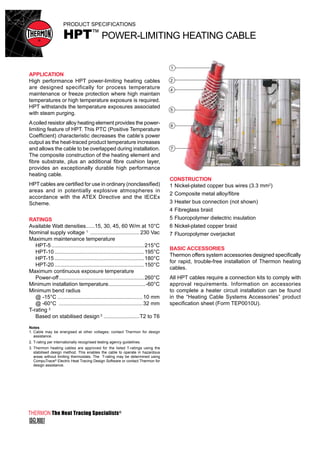

The document describes an HPTTM power-limiting heating cable made by Thermon. The cable has a nickel-plated copper bus wire core surrounded by a composite metal alloy fiber and fiberglass braid insulation. It is designed for high temperature process maintenance and freeze protection up to 260°C. The cable uses a coiled resistor alloy heating element that provides power limiting as temperature increases to allow for overlapping installation. It is approved for use in ordinary and hazardous explosive atmospheres.


