SlideShare a Scribd company logo
1 of 81
Download to read offline
Solar Thermal Engineering
1
3 – Flat Plate Collectors
Instructor: Dr Solomon T/Mariam Teferi
Addis Ababa institute of Technology – Addis Ababa University
April 2020
3.1 INTRODUCTION
 Solar collectors are heat exchangers that use solar radiation to
heat a working fluid, usually liquid or air. They can be classified
in three groups:
 Flat-plate collectors
 Evacuated-tube collector
 Focusing collectors
 In flat-plate collectors, there is no optical concentration of
sunlight and they are generally stationary
 their outlet temperature capability not exceeding 100°C
 In evacuated-tube collectors, there is vacuun to reduce heat lost
and to protect the absorber coating from deteration
 Temperatures up to 140°C
 they can collect both direct and diffuse solar radiation
 Focusing collectors, they follow the sun to get direct radiation
 They can not utilize diffuse radiation.
 they are also capable of producing high temperatures
3
Mail Components of a Typical Flat Plate Collector
Flat plate collector is typically a metal box with
 a glass or plastic cover (called glazing) on top
 and a dark-colored absorber plate on the bottom
 the sides and bottom of the collector are usually insulated to
minimize heat loss
 Absorber plate:
It is usually made of copper, steel or plastic. The surface is covered
with a flat black material of high absorptance.
If copper or steel is used it is possible to apply a selective coating
that maximizes the absorptance of solar energy and minimizes the
radiation emitted by plate.
 Flow passages:
The flow passages conduct the working fluid through the collector.
If the working fluid is a liquid , the flow passage is usually a tube
that is attached to or is a part of absorber plate.
If the working fluid is air, the flow passage should be below the
absorber plate to minimize heat losses.
4
 Cover plate:
 To reduce convective and radiative heat losses from the
absorber, one or two transparent covers are generally placed
above the absorber plate.
 They usually be made from glass or plastic.
 Insulation
 Insulation is some material such as fiberglass and it is placed
at the back and sides of the collector to reduce heat losses.
 Enclosure
 Enclosure is used holds the components together, protect them
from weather, facilitates installation of the collector on a roof
or appropriate frame.
Absorber plate & Flow passages
 Copper,which has high conductivity and is corrosion-resistant, is the
material for absorber plates,
 but since copper is expensive, steel is also widely used.
 The surface of the absorber plate determines how much of the
incident solar radiation is absorbed and how much is emitted at a
given temperature.
 Flat black paint which is widely used as a coating has an absorptance of about
95 percent for incident shortwave solar radiation. It is durable and easy to apply.
Material Absorptance
()
Emittance
()
Break down
temparature (°C)
Comments
Black silicon
paint
0.86-0.94 0.83-0.89 350 Slicone binder
Black silicon
paint
0.9 0.5 Stable at high
temperature
Black copper
over copper
0.85-0.9 0.08-0.12 450 Patinates with
moisture
Black chorome
over nickel
0.92-0.94 0.07-0.12 450 Stable at high
temperatures
Cover plates
 A cover plate for a collector should have a high transmittance for
solar radiation and should not detoriate with time.
 The material most commonly used is glass. A 0.32-cm thick sheet of window
glass ( iron content, 0.12 percent ) transmits 85 percent of solar energy at normal
incidence.
 And all glasses are opaque to long-wavelength radiation emitted by the absorber
 Some plastic materials can be used for collector glazing.
 They are cheaper and lighter than glass and,
 However, they are not as durable as glass and they often degrade with exposure
to ultraviolet radiation or high temperatures.
Test Polyvinly
floride
Polyethylene
terephthatalet
or polyster
Polycarbonate Fiberglass rein
forced plastics
Solar Transmission, % 92-94 85 82-89 77-90
Maximu operating
temperature°C
110 100 120-135 95
Thermal Expansion
Coefficient
43 27 68 32-40
Thickness, mm 0.1 0.025 3.2 1.0
Length of life, years In 5 years 95% retains 4 7-20
Characteristics of insulation materials
Material Density Kg/m3 Thermal
conductivity at
95 °C (W/mK)
Temperature
limits °C
Fiber glass with
organic binder
11 0.059 175
“ 16 0.050 175
“ 24 0.045 175
“ 48 0.043 175
Proper Orientatıon -Angle of Solar Collector
Flat plate collectorts are divided in three main
groups according to how they are oriented:
 Flat-plate collectors facing south at fixed tilt
 One-axis tracking flat-plate collectors with axis
oriented north-south
 Two-axis tracking flat-plate collectors
Flat-plate Collectors Facing South at Fixed Tilt
http://rredc.nrel.gov/solar/pubs/redbook/html/interp.html
To optimize performance in the winter, the collector can be
tilted 15 ° greater than the latitude; to optimize performance in
the summer, the collector can be tilted 15° less than the
latitude. .
One-axis tracking flat-plate collectors with
axis oriented north-south:
These trackers pivot on their single axis to track the sun, facing
east in the morning and west in the afternoon
Two-axis tracking flat-plate collectors:
Tracking the sun in both azimuth and elevation, these
collectors keep the sun's rays normal to the collector
3.2 COLLECTOR PERFORMANCE
John A. Duffie and William A. Beckman
Basic Energy Balance Equation
 In steady state, the performance of a solar collector
is described by an energy balance that indicates the
distribution of incident solar energy into:
 Useful energy gain, Thermal losses, and Optical losses
 Useful Energy Gain by the Collector ( Qu ) =
= Energy Absorbedby the Collector – Heat Loss to Surroundings
 In steady state the useful energy output of a
collector of area is
 The absorbed solar radiation – thermal Losses
13
Where
 S solar radiation absorbed by the solar collector
 S = Incident solar radiation - Optical Losses
• are the view factors from the collector to
the sky and from the collector to the ground, respectively. The
subscripts b,d, and g represent beam, diffuse, and ground ,
respectively
• is transmittance and absorptance product
• Rb is the ratio of beam radiation on the tilted surface to that on
a horizantal surface at any time
 UL (Tpm - Ta) is the thermal energy lost from the collector plate to the
surroundings by conduction, convection, and infrared radiation
 UL is the collector overall loss coefficient and it is equal to the sum of
the top, bottom,and edge loss coefficients, UL=Utop+Ubottom+Uedge,W/m²K
 Tpm, Ta and are mean absorber plate and ambient temperatures
 Ac is collector area 14
 The problem with eq (1) is that the mean
absorber plate temperature is difficult to
calculate or measure since it is a function of
 the collector design, the incident solar radiation,
and the entering fluid conditions.
15
Temperature distribution between tubes and the collector
efficiency factor
 The function F is the
standard fin efficiency
for straight fins with
rectangular profile and
is plotted in next Figure
16
17
 We now wish to eliminate Tb from the equations and
obtain an expression for the useful gain in terms of
known dimensions, physical parameters, and the
local fluid temperature.
 The collector efficiency factor is essentially a
constant for any collector design and fluid flow rate.
18
19
 Hence, an equation is formulated to replace eq (1) so that
the useful energy gain can be expressed in terms of the inlet
fluid temperature and a parameter called the collector heat
removal factor (FR) which can be evaluated analytically
from basic principles or experimentally measured data
 This parameter relates the actual useful energy gain of a
collector to the useful gain if the whole collector surface
were at the fluid inlet temperature.
 This equation is as follow
Qu = AcFRS – AcFRUL(Ti – Ta ) or
 This equation is an extremely useful equation and applies to
essentialy all flat-plate collectors.
20
 Equation (2) can be rewritten as
Where
 Collector heat Removal Factor (FR)
 m = Fluid mass flow rate, kg/s
 Cp = Fluid specific heat, J/kg°C
 The quantitiy FR is equavialent to the effectiveness of a conventional
heat exchange, which is defined as the ratio of the actual heat transfer to
the maximum possible heat transfer. The maximum possible useful
energy gain (heat transfer) in a solar collector occurs when the all whole
collector is at the inlet fluid temperature; heat losses to the surroudings
are then at a minimum.
 is a transmittance-absorptance product that is weighted according
to the proportions of beam, diffuse, and ground reflected radiation on the
collector
21
 The basic method of measuring collector performance
is to expose the operating collector to solar radiation
and measure the fluid inlet and outlet temperatures
and the fluid flow rate.The useful gain is
 Where;
 m = Fluid mass flow rate, kg/s
 Cp = Fluid specific heat, J/kg°C
22
 What information is given in the diagram above
 It is a diagram of typical flat plate collector
 92 % of the total sunshine reaches to the copper
absorber.
 8% of the total sunshine is reflected from glass.
 5% of the sunshine is emitted from the panel
 12% is lost through convection and conduction 23
Collector Effıcıency
 the collection efficiency is the ratio of the useful
gain over some specified time period to the
incident solar energy over the same time period:
 The instantaneous efficiency
24
3.3 TEMPERATURE DISTRIBUTIONS IN FLAT-
PLATE COLLECTORS
John A. Duffie and William A. Beckman
25
 Figure (a) shows a region between
two tubes.
Some of the solar energy absorbed by
the plate must be conducted along the
plate to the region of the tubes. Thus the
temperature midway between the tubes
will be higher than the temperature in
the vicinity of the tubes.
The temperature above the tubes will be
nearly uniform because of the presence
of the tube and weld metal.
The energy transferred to the fluid
will heat the fluid, causing a
temperature gradient to exist in the
direction of flow.
 Since in any region of the collector the general
temperature level is governed by the local temperature
level of the fluid, a situation as shown in Figure (b) is
expected.
 At any location y, the general temperature distribution in
the x direction is as shown in Figure (c), and
 At any location x, the temperature distribution in the y
direction is as shown in Figure (d).
26
To model the situation shown in the figure, a number of
simplifying assumptions can be made to lay the
foundations without obscuring the basic physical situation.
These are:
 Performance is steady state.
 Construction is of sheet and parallel tube
type
 The headers cover a small area of collector
and can be neglected
 The headers provide uniform flow to tubes
 There is no absorption of solar energy by a
cover insofar as it affects losses from the
collector.
 Heat flow through a cover is one
dimensional
 There is a negligible temperature drop
through a cover
 The covers are opaque to infrared radiation
 There is one-dimensional heat flow through
back insulation 27
 The sky can be considered as a
blackbody for long-wavelength radiation
at an equivalent sky temperature
 Temperature gradients around tubes can
be neglected
 The temperature gradients in the
direction of flow and between the tubes
can be treated independently
 Properties are independent of
temperature
 Loss through front and back are to the
same ambient temperature
 Dust and dirt on the collector are
negligible
 Shading of the collector absorber plate is
negligible.
3.4 COLLECTOR OVERALL HEAT LOSS COEFFICIENT
John A. Duffie and William A. Beckman
 The absorbed energy S is distributed to
 To thermal losses through the top, bottom and edge
 To useful energy gain
 The energy loss through the top is the result of
convection and radiation between parallel plates.
 The steady-state energy transfer between the plate at
Tp and the first cover at Tc1 is the same as between any
other two adjacent covers and is also equal to the
energy lost to the surroundings from the top cover.
28
 Thermal network for a two-cover
flat-plate collector:
 (a) in terms of conduction,
convection, and radiation
resistances;
 (b) in terms of resistances
between plates.
 (c) Equivalent thermal network
for flat-plate solar collector. 29
Where
 h c,p-c1 is the convection heat transfer coefficient
between the absorber plate and the frist glass coverer
 If the definition of the radiation heat transfer coefficient
is to be used, the heat loss equation becomes 30
3.4.1 Top Loss
Heat Loss from the absorber Plate to the first glass cover
Heat Loss from the first glass cover to the Second Glass Cover
 A similar expression can be written for R2, the
resistance between the two glass covers.
31
Heat Loss from the Second Glass Cover to the Surrounding
 The heat loss from flat plates exposed to outside winds is
important in the study of solar collectors
 Therefore, for two-cover system, the top loss coefficient
from the collector plate to the ambient Ut is
32
 In solving the top loss coefficient using Equations
7 to15 is necessarily an iterative process.
 First a guess is made of the unknown cover
temperatures, from which the convective and radiative
heat transfer coefficients between parallel surfaces are
calculated. With these estimates, Equation 15 can be
solved for the top loss coefficient.
The top heat loss is the top loss coefficient times the
overall temperature difference, and since the energy
exchange between plates must be equal to the overall
heat loss, a new set of cover temperatures can be
calculated. Beginning at the absorber plate, a new
temperature is calculated for the first cover.
33
 This new first cover temperature is used to find the
next cover temperature, and so on. For any two
adjacent covers or plate, the new temperature of plate
(cover) j can be expressed in terms of the
temperature of plate (cover) i as
 The process is repeated until the cover temperatures
do not change significantly between successive
iterations. The following example illustrates the
process.
34
Example
(Example 6.4.1Text book)
 Calculate the to loss coefficient for an absorber with a single
glass cover having the following specifications:
Plate-to-cover spacing 25 mm
Plate emittance 0.95
Ambient air and sky temperature 10oC
Wind heat transfer coefficient 10W/m2oC
Mean plate temperature (Tp) 100oC
Collector tilt 45o
Glass emittance 0.88
35
36
 The procedure is to estimate the cover temperature, from
which hc,p-c, hr,p-c and hr,c-a are calculated. With these heat
transfer coefficients and hw, the top loss coefficient is
calculated. These results are then used to calculate Tc from the
preceding equation,. If Tc is close to the initial guess, no
further calculations are necessary. Otherwise, the newly
calculated Tc is used and the process is repeated.
Let first assume Tc =35oC. With this the two radiation coefficient are
hr,p-c = 7.60 W/m2, hr,c-a = 5.16W/m2
The mean temperature b/n the plate and the cover is (100+35)/2 = 67.5oC.
At this temperature the air properties are
37
38
39
40
 The calculation of the top loss coefficient is a
tedious process.
 To simplify calculations of collector
performance, Figures (a–f) have been prepared.
These figures give the top loss coefficient for
one, two, and three glass covers.
41
 Even though the top loss coefficients of figures a- f are for a plate
spacing of 25 mm, they can be used for other plate spacing with
little error as long as the spacing is greater than about 15 mm.
42
43
44
Typical Variation of Top Loss Coefficient with Plate Spacing
using a slope ß of 45o
 N is number of glass plates
45
Dependence of top loss coefficient on slope.
46
 An empirical equation for Ut that is useful for both hand and
computer calculations was developed by Klein (1979) following the
basic procedure of Hottel and Woertz (1942) and Klein (1975). This
relationship fits the graphs for Ut for mean plate temperatures b/n
ambient and 200oC to within ±0.3 W/m2 oC.
47
48
49
3.4.1 Bottom Loss
 The energy loss through the bottom of the collector is
represented by two series resistors,
 R4 (represents the resistance to heat flow) and R5
(Represents the convection and radiation resistance to the
environment.
 The magnitudes of R4 and R5 are such that it is usually
possible to assume R5 is zero and all resistance to heat
flow is due to the insulation. Thus, the back loss
coefficient Ub is approximately
 where k and L are the insulation thermal conductivity and
thickness, respectively.
50
3.4.1 Edge Loss
 Tabor (1958) recommends edge insulation of
about the same thickness as bottom insulation.
 The edge losses are then estimated by assuming one-
dimensional sideways heat flow around the perimeter
of the collector system.
 The losses through the edge should be referenced to
the collector area. If the edge loss coefficient–area
product is (UA)edge, then the edge loss coefficient,
based on the collector area Ac ,is
51
 If it is assumed that all losses occur to a common
sink temperature Ta, the collector overall loss
coefficient UL is the sum of the top, bottom, and
edge loss coefficients
52
53
 The edge loss for this 30-m2 collector array is a little over 1% of the
total losses. Note, however, that if this collector were 1 × 2 m, the
edge losses would increase to over 5%.
 Thus, edge losses for well-constructed large collector arrays are
usually negligible, but for small arrays or individual modules the
edge losses may be significant. Also note that only the exterior
perimeter was used to estimate edge losses.
 If the individual collectors are not packed tightly together, significant
heat loss may occur from the edge of each module. 54
 The preceding discussion of top loss coefficients, are based on
covers like glass that are opaque to long-wavelength radiation.
 If a plastic material must be modified to account for some infrared
radiation passing directly through the cover. For a single cover that is
partially transparent to infrared radiation, the net radiant energy transfer
directly between the collector plate and the sky is used to replace one or
more covers, the equation for Ut must be modified to account for some
infrared radiation passing directly through the cover. For a single cover
that is partially transparent to infrared radiation, the net radiant
energy transfer directly between the collector plate and the sky is
 where τc and ρc are the transmittance and reflectance of the cover for
radiation from Tp and from Ts (assuming that the transmittance is
independent of source temperature or that Tp and Ts are nearly the
same) and εp and ρp are the emittance and reflectance of the plate for
long-wave radiation. 55
 The top loss coefficient then becomes
 The evaluation of the radiation heat transfer coefficients in Equation
(22) must take into account that the cover is partially transparent.
 The net radiation between the opaque plate and the partially
transparent cover is given by
 The radiation heat transfer coefficient between the plate and cover is
just the net heat transfer divided by the temperature difference:
56
3.5 EFFECTS OF DUST AND SHADING
John A. Duffie and William A. Beckman
 The effects of dust and shading are difficult to generalize.
 Data reported by Dietz (1963) show that at the angles of
incidence of interest (0 to 50o) the maximum reduction of
transmittance of covers due to dirt was 2.7%. From long-term
experiments on collectors in the Boston area, Hottel and
Woertz (1942) found that collector performance decreased
approximately 1% due to dirty glass.
 In a rainless 30-day experiment in India, Garg (1974) found
that dust reduced the transmittance by an average of 8% for
glass tilted at 45o.
 To account for dust in temperate climates, it is
suggested that radiation absorbed by the plate be
reduced by 1%; in dry and dusty climates, absorbed
radiation can be reduced by 2%. 57
 Shading effects can also be significant.
 Whenever the angle of incidence is off normal, some of the
collector structure will intercept solar radiation.
 Some of this radiation will be reflected to the absorbing
plate if the sidewalls are of a high-reflectance material.
Hottel and Woertz (1942), based on experiments with two-
cover collectors, recommend that the radiation absorbed by
the plate be reduced by 3% to account for shading effects if
the net (unobstructed) glass area is used in all calculations.
The net glass area accounts for the blockage by the supports
for the glass. Most modern collectors use one cover, and
module areas are larger, both of which reduce shading
effects.
 A reduction of S of 1% may be a more appropriate
correction for these collectors.
58
 Where KL is extinction length, K is proportionality constant
(extinction coefficient) which is assumed to be a constant in the solar
spectrum. K varies from approximately 4 m−1 for ‘‘water white’’ glass
to approximately 32 m−1 for high iron oxide content glass.
59
3.6 SOLAR LIQUID HEATER
 The first three have parallel tubes (risers)
thermally fastened to a plate and connected at
the top and bottom by headers to admit and
remove the liquid.
 The design shown in (b) is the same as (a),
except that the tubes are mounted on top of the
plate rather than under it.
 (c) has the tubes centered in the plane of the
plate forming an integral part of the plate
structure.
 (d), (e), and (f), long, narrow, flat absorbers are
mounted inside evacuated glass tubes.
 (g) the serpentine tube arrangement
61
62
63
 For a single bend, Zhang and Lavan show that the
solution for FR is given by the equation below in terms
of three dimensionless parameters F1, F2, and F3 (the
parameters F4, F5, and F6 are functions of F2 only)
64
 Zhang and Lavan (1985) point out that Equation
(25) is valid for any number of bends if the group
mcp / F1ULAcis greater than about 1.0.
 For smaller values of this group, their paper
should be consulted.
65
66
67
68
 The most common liquid solar heater is uncovered
and used for low-temperature applications such as
swimming pool heating.
 These collectors are typically made from plastics
such as stabilized polyolefin.
 The parallel-flow channels either are in direct contact
with one another or are connected by very short fins.
 The short fins are necessary due to the low thermal
conductivity of the plastic material.
 The same basic equations apply for these collectors,
but the lack of a cover means that estimating the
collector loss coefficient is very uncertain.
69
3.7 SOLAR AIR HEATERS
70
71
 At some location along the flow direction the absorbed
solar energy heats up the plate to a temperature Tp.
 Energy is transferred from the plate to the ambient air at Ta
through the back loss coefficient Ub , to the fluid at Tf
through the convection heat transfer coefficient h2, and to
the bottom of the cover glass through the linearized
radiation heat transfer coefficient h1.
 Energy is transferred to the cover glass from the fluid
through the heat transfer coefficient hr.
 Energy is lost to the ambient air through the combined
convection and radiation coefficient Ut.
 Note that Ut can account for multiple covers.
 Energy balances on the cover, the plate, and the fluid
yield the following equations: 72
 These three equations are solved so that the useful
gain is expressed as a function of Ut, h1, h2, hr, Tf, and
Ta.
 In other words, Tp and Tc must be eliminated. The algebra
is somewhat tedious and only a few of the intermediate
steps are given. Solving the first two equations for Tp – Tf
and Tc – Tf,
73
 Substituting these into the equation for qu and
rearranging, we obtain
74
 Note that UL for this collector is not just the top loss
coefficient in the absence of back losses but also accounts
for heat transfer between the absorbing surface and the
bottom of the cover.
 Whenever the heat removal fluid is in contact with a
transparent cover, UL will be modified in a similar
fashion.
 The equations for type (b) air heaters are derived in a
similar manner, but the working fluid does not contact the
cover system.
 For simplicity, back losses are assumed to occur from the
absorber plate temperature. The following example shows
calculation of the performance of a type (b) air heater.
75
76
77
78
79
80
81

More Related Content

What's hot

solar radiation measurement vivek singh
solar radiation measurement vivek singhsolar radiation measurement vivek singh
solar radiation measurement vivek singhvivek singh
 
Solar collectors and applications
Solar collectors and applicationsSolar collectors and applications
Solar collectors and applicationsViplav Halder
 
Solar flat plate collector
Solar flat plate collectorSolar flat plate collector
Solar flat plate collectorBipin Gupta
 
SOLAR THERMAL PLANT
SOLAR THERMAL PLANTSOLAR THERMAL PLANT
SOLAR THERMAL PLANTAJAY RAO
 
Performance Analysis of Liquid Flat Plate collector and PV Cell
Performance Analysis of Liquid Flat Plate collector and PV CellPerformance Analysis of Liquid Flat Plate collector and PV Cell
Performance Analysis of Liquid Flat Plate collector and PV CellDr Ramesh B T
 
SOLAR RADIATION MEASUREMENT
SOLAR RADIATION MEASUREMENTSOLAR RADIATION MEASUREMENT
SOLAR RADIATION MEASUREMENTVanita Thakkar
 
Oro551 res- unit 1 - extra terrestrial and terrestrial solar radiation
Oro551   res- unit 1 - extra terrestrial and terrestrial solar radiationOro551   res- unit 1 - extra terrestrial and terrestrial solar radiation
Oro551 res- unit 1 - extra terrestrial and terrestrial solar radiationkarthi keyan
 
Solar radiation on tilted surface.
Solar radiation on tilted surface.Solar radiation on tilted surface.
Solar radiation on tilted surface.MadhuriPawar37
 
Solar energy applications
Solar energy applicationsSolar energy applications
Solar energy applicationsMehul111
 

What's hot (20)

solar radiation measurement vivek singh
solar radiation measurement vivek singhsolar radiation measurement vivek singh
solar radiation measurement vivek singh
 
Solar energy storage
Solar energy storageSolar energy storage
Solar energy storage
 
solar collectors
solar collectorssolar collectors
solar collectors
 
REC.ppt
REC.pptREC.ppt
REC.ppt
 
Solar collector
Solar collectorSolar collector
Solar collector
 
solar energy
solar energysolar energy
solar energy
 
Solar collectors and applications
Solar collectors and applicationsSolar collectors and applications
Solar collectors and applications
 
Solar flat plate collector
Solar flat plate collectorSolar flat plate collector
Solar flat plate collector
 
SOLAR THERMAL PLANT
SOLAR THERMAL PLANTSOLAR THERMAL PLANT
SOLAR THERMAL PLANT
 
Performance Analysis of Liquid Flat Plate collector and PV Cell
Performance Analysis of Liquid Flat Plate collector and PV CellPerformance Analysis of Liquid Flat Plate collector and PV Cell
Performance Analysis of Liquid Flat Plate collector and PV Cell
 
SOLAR RADIATION MEASUREMENT
SOLAR RADIATION MEASUREMENTSOLAR RADIATION MEASUREMENT
SOLAR RADIATION MEASUREMENT
 
Solar pond
Solar pondSolar pond
Solar pond
 
Solar Air Heater
Solar Air HeaterSolar Air Heater
Solar Air Heater
 
Oro551 res- unit 1 - extra terrestrial and terrestrial solar radiation
Oro551   res- unit 1 - extra terrestrial and terrestrial solar radiationOro551   res- unit 1 - extra terrestrial and terrestrial solar radiation
Oro551 res- unit 1 - extra terrestrial and terrestrial solar radiation
 
Solar Thermal Power
Solar Thermal PowerSolar Thermal Power
Solar Thermal Power
 
Concentrator Solar Power Plants
Concentrator Solar Power PlantsConcentrator Solar Power Plants
Concentrator Solar Power Plants
 
Solar radiation on tilted surface.
Solar radiation on tilted surface.Solar radiation on tilted surface.
Solar radiation on tilted surface.
 
Solar energy applications
Solar energy applicationsSolar energy applications
Solar energy applications
 
4841_CH3_Solar Collector_M A Islam
4841_CH3_Solar Collector_M A Islam4841_CH3_Solar Collector_M A Islam
4841_CH3_Solar Collector_M A Islam
 
Solar Energy
Solar EnergySolar Energy
Solar Energy
 

Similar to Solar Thermal Engineeirng chap 3.pdf

Flat plate collector by SAURABH KUMAR YADAV
Flat plate collector by SAURABH KUMAR YADAVFlat plate collector by SAURABH KUMAR YADAV
Flat plate collector by SAURABH KUMAR YADAVSAURABH KUMAR YADAV
 
Renewable energy course#05
Renewable energy course#05Renewable energy course#05
Renewable energy course#05Syed_Sajjad_Raza
 
eme.pptMechanical engineering is the study of physical machines that may invol
eme.pptMechanical engineering is the study of physical machines that may involeme.pptMechanical engineering is the study of physical machines that may invol
eme.pptMechanical engineering is the study of physical machines that may involVINODN33
 
Sg nsgnsgsymmehemyeym, ynwnwybwybwybwtbwtwbtqbtwgbgbwwywgnnwynwgnwgwgnSolar C...
Sg nsgnsgsymmehemyeym, ynwnwybwybwybwtbwtwbtqbtwgbgbwwywgnnwynwgnwgwgnSolar C...Sg nsgnsgsymmehemyeym, ynwnwybwybwybwtbwtwbtqbtwgbgbwwywgnnwynwgnwgwgnSolar C...
Sg nsgnsgsymmehemyeym, ynwnwybwybwybwtbwtwbtqbtwgbgbwwywgnnwynwgnwgwgnSolar C...SuryaTejaVutti
 
NCES Module-3.pptx
NCES  Module-3.pptxNCES  Module-3.pptx
NCES Module-3.pptxShivaniGaj
 
Solar Calculation (44 slide)
 Solar Calculation (44 slide) Solar Calculation (44 slide)
Solar Calculation (44 slide)Rami Hassbini
 
solat thermal power plant.pptx
solat thermal power plant.pptxsolat thermal power plant.pptx
solat thermal power plant.pptxPuspitaDas13
 
Solar energy concentration techniques in flat plate collector
Solar energy concentration techniques in flat plate collectorSolar energy concentration techniques in flat plate collector
Solar energy concentration techniques in flat plate collectorIAEME Publication
 
Solar energy concentration techniques in flat plate collector
Solar energy concentration techniques in flat plate collectorSolar energy concentration techniques in flat plate collector
Solar energy concentration techniques in flat plate collectorIAEME Publication
 
Flat plate collector by Nishant Raj Kapoor
Flat plate collector by Nishant Raj KapoorFlat plate collector by Nishant Raj Kapoor
Flat plate collector by Nishant Raj KapoorNishant Raj Kapoor
 
Flate Plate Collector (theory presentation).pdf
Flate Plate Collector (theory presentation).pdfFlate Plate Collector (theory presentation).pdf
Flate Plate Collector (theory presentation).pdfFaizanAhmed396943
 
Solar energy introduction
Solar energy introductionSolar energy introduction
Solar energy introductionStalin Kesavan
 
Three solar air heater having different absorber areas by Er. Vikas Manushendra
Three solar air heater having different absorber areas by Er. Vikas ManushendraThree solar air heater having different absorber areas by Er. Vikas Manushendra
Three solar air heater having different absorber areas by Er. Vikas ManushendraVikas Manushendra
 
Three solar air heater having different absorber areas by er. vikas manushendra
Three solar air heater having different absorber areas by er. vikas manushendraThree solar air heater having different absorber areas by er. vikas manushendra
Three solar air heater having different absorber areas by er. vikas manushendraVikas Manushendra
 
Solar Thermal in power generation for cleaner
Solar Thermal in power generation for cleanerSolar Thermal in power generation for cleaner
Solar Thermal in power generation for cleanerHWNoorShieela1
 
IRJET- Efficiency Improvement and Performance Analysis of Solar Collector...
IRJET-  	  Efficiency Improvement and Performance Analysis of Solar Collector...IRJET-  	  Efficiency Improvement and Performance Analysis of Solar Collector...
IRJET- Efficiency Improvement and Performance Analysis of Solar Collector...IRJET Journal
 

Similar to Solar Thermal Engineeirng chap 3.pdf (20)

Flat plate collector by SAURABH KUMAR YADAV
Flat plate collector by SAURABH KUMAR YADAVFlat plate collector by SAURABH KUMAR YADAV
Flat plate collector by SAURABH KUMAR YADAV
 
Renewable energy course#05
Renewable energy course#05Renewable energy course#05
Renewable energy course#05
 
eme.pptMechanical engineering is the study of physical machines that may invol
eme.pptMechanical engineering is the study of physical machines that may involeme.pptMechanical engineering is the study of physical machines that may invol
eme.pptMechanical engineering is the study of physical machines that may invol
 
Sg nsgnsgsymmehemyeym, ynwnwybwybwybwtbwtwbtqbtwgbgbwwywgnnwynwgnwgwgnSolar C...
Sg nsgnsgsymmehemyeym, ynwnwybwybwybwtbwtwbtqbtwgbgbwwywgnnwynwgnwgwgnSolar C...Sg nsgnsgsymmehemyeym, ynwnwybwybwybwtbwtwbtqbtwgbgbwwywgnnwynwgnwgwgnSolar C...
Sg nsgnsgsymmehemyeym, ynwnwybwybwybwtbwtwbtqbtwgbgbwwywgnnwynwgnwgwgnSolar C...
 
Solar power plant
Solar power plantSolar power plant
Solar power plant
 
NCES Module-3.pptx
NCES  Module-3.pptxNCES  Module-3.pptx
NCES Module-3.pptx
 
Solar Calculation (44 slide)
 Solar Calculation (44 slide) Solar Calculation (44 slide)
Solar Calculation (44 slide)
 
parabolic refclector
parabolic refclector parabolic refclector
parabolic refclector
 
solat thermal power plant.pptx
solat thermal power plant.pptxsolat thermal power plant.pptx
solat thermal power plant.pptx
 
Solar energy concentration techniques in flat plate collector
Solar energy concentration techniques in flat plate collectorSolar energy concentration techniques in flat plate collector
Solar energy concentration techniques in flat plate collector
 
Solar energy concentration techniques in flat plate collector
Solar energy concentration techniques in flat plate collectorSolar energy concentration techniques in flat plate collector
Solar energy concentration techniques in flat plate collector
 
Flat plate collector by Nishant Raj Kapoor
Flat plate collector by Nishant Raj KapoorFlat plate collector by Nishant Raj Kapoor
Flat plate collector by Nishant Raj Kapoor
 
Fpc by n.raj
Fpc by n.rajFpc by n.raj
Fpc by n.raj
 
Flate Plate Collector (theory presentation).pdf
Flate Plate Collector (theory presentation).pdfFlate Plate Collector (theory presentation).pdf
Flate Plate Collector (theory presentation).pdf
 
Solar energy introduction
Solar energy introductionSolar energy introduction
Solar energy introduction
 
Three solar air heater having different absorber areas by Er. Vikas Manushendra
Three solar air heater having different absorber areas by Er. Vikas ManushendraThree solar air heater having different absorber areas by Er. Vikas Manushendra
Three solar air heater having different absorber areas by Er. Vikas Manushendra
 
Three solar air heater having different absorber areas by er. vikas manushendra
Three solar air heater having different absorber areas by er. vikas manushendraThree solar air heater having different absorber areas by er. vikas manushendra
Three solar air heater having different absorber areas by er. vikas manushendra
 
Solar Thermal in power generation for cleaner
Solar Thermal in power generation for cleanerSolar Thermal in power generation for cleaner
Solar Thermal in power generation for cleaner
 
IRJET- Efficiency Improvement and Performance Analysis of Solar Collector...
IRJET-  	  Efficiency Improvement and Performance Analysis of Solar Collector...IRJET-  	  Efficiency Improvement and Performance Analysis of Solar Collector...
IRJET- Efficiency Improvement and Performance Analysis of Solar Collector...
 
Fq3310001010
Fq3310001010Fq3310001010
Fq3310001010
 

Recently uploaded

HARMONY IN THE NATURE AND EXISTENCE - Unit-IV
HARMONY IN THE NATURE AND EXISTENCE - Unit-IVHARMONY IN THE NATURE AND EXISTENCE - Unit-IV
HARMONY IN THE NATURE AND EXISTENCE - Unit-IVRajaP95
 
Heart Disease Prediction using machine learning.pptx
Heart Disease Prediction using machine learning.pptxHeart Disease Prediction using machine learning.pptx
Heart Disease Prediction using machine learning.pptxPoojaBan
 
Churning of Butter, Factors affecting .
Churning of Butter, Factors affecting  .Churning of Butter, Factors affecting  .
Churning of Butter, Factors affecting .Satyam Kumar
 
complete construction, environmental and economics information of biomass com...
complete construction, environmental and economics information of biomass com...complete construction, environmental and economics information of biomass com...
complete construction, environmental and economics information of biomass com...asadnawaz62
 
Past, Present and Future of Generative AI
Past, Present and Future of Generative AIPast, Present and Future of Generative AI
Past, Present and Future of Generative AIabhishek36461
 
Concrete Mix Design - IS 10262-2019 - .pptx
Concrete Mix Design - IS 10262-2019 - .pptxConcrete Mix Design - IS 10262-2019 - .pptx
Concrete Mix Design - IS 10262-2019 - .pptxKartikeyaDwivedi3
 
Call Girls Delhi {Jodhpur} 9711199012 high profile service
Call Girls Delhi {Jodhpur} 9711199012 high profile serviceCall Girls Delhi {Jodhpur} 9711199012 high profile service
Call Girls Delhi {Jodhpur} 9711199012 high profile servicerehmti665
 
Artificial-Intelligence-in-Electronics (K).pptx
Artificial-Intelligence-in-Electronics (K).pptxArtificial-Intelligence-in-Electronics (K).pptx
Artificial-Intelligence-in-Electronics (K).pptxbritheesh05
 
EduAI - E learning Platform integrated with AI
EduAI - E learning Platform integrated with AIEduAI - E learning Platform integrated with AI
EduAI - E learning Platform integrated with AIkoyaldeepu123
 
An experimental study in using natural admixture as an alternative for chemic...
An experimental study in using natural admixture as an alternative for chemic...An experimental study in using natural admixture as an alternative for chemic...
An experimental study in using natural admixture as an alternative for chemic...Chandu841456
 
Application of Residue Theorem to evaluate real integrations.pptx
Application of Residue Theorem to evaluate real integrations.pptxApplication of Residue Theorem to evaluate real integrations.pptx
Application of Residue Theorem to evaluate real integrations.pptx959SahilShah
 
pipeline in computer architecture design
pipeline in computer architecture  designpipeline in computer architecture  design
pipeline in computer architecture designssuser87fa0c1
 
UNIT III ANALOG ELECTRONICS (BASIC ELECTRONICS)
UNIT III ANALOG ELECTRONICS (BASIC ELECTRONICS)UNIT III ANALOG ELECTRONICS (BASIC ELECTRONICS)
UNIT III ANALOG ELECTRONICS (BASIC ELECTRONICS)Dr SOUNDIRARAJ N
 
VICTOR MAESTRE RAMIREZ - Planetary Defender on NASA's Double Asteroid Redirec...
VICTOR MAESTRE RAMIREZ - Planetary Defender on NASA's Double Asteroid Redirec...VICTOR MAESTRE RAMIREZ - Planetary Defender on NASA's Double Asteroid Redirec...
VICTOR MAESTRE RAMIREZ - Planetary Defender on NASA's Double Asteroid Redirec...VICTOR MAESTRE RAMIREZ
 
Biology for Computer Engineers Course Handout.pptx
Biology for Computer Engineers Course Handout.pptxBiology for Computer Engineers Course Handout.pptx
Biology for Computer Engineers Course Handout.pptxDeepakSakkari2
 
What are the advantages and disadvantages of membrane structures.pptx
What are the advantages and disadvantages of membrane structures.pptxWhat are the advantages and disadvantages of membrane structures.pptx
What are the advantages and disadvantages of membrane structures.pptxwendy cai
 

Recently uploaded (20)

HARMONY IN THE NATURE AND EXISTENCE - Unit-IV
HARMONY IN THE NATURE AND EXISTENCE - Unit-IVHARMONY IN THE NATURE AND EXISTENCE - Unit-IV
HARMONY IN THE NATURE AND EXISTENCE - Unit-IV
 
Heart Disease Prediction using machine learning.pptx
Heart Disease Prediction using machine learning.pptxHeart Disease Prediction using machine learning.pptx
Heart Disease Prediction using machine learning.pptx
 
Churning of Butter, Factors affecting .
Churning of Butter, Factors affecting  .Churning of Butter, Factors affecting  .
Churning of Butter, Factors affecting .
 
complete construction, environmental and economics information of biomass com...
complete construction, environmental and economics information of biomass com...complete construction, environmental and economics information of biomass com...
complete construction, environmental and economics information of biomass com...
 
Past, Present and Future of Generative AI
Past, Present and Future of Generative AIPast, Present and Future of Generative AI
Past, Present and Future of Generative AI
 
Concrete Mix Design - IS 10262-2019 - .pptx
Concrete Mix Design - IS 10262-2019 - .pptxConcrete Mix Design - IS 10262-2019 - .pptx
Concrete Mix Design - IS 10262-2019 - .pptx
 
Call Girls Delhi {Jodhpur} 9711199012 high profile service
Call Girls Delhi {Jodhpur} 9711199012 high profile serviceCall Girls Delhi {Jodhpur} 9711199012 high profile service
Call Girls Delhi {Jodhpur} 9711199012 high profile service
 
9953056974 Call Girls In South Ex, Escorts (Delhi) NCR.pdf
9953056974 Call Girls In South Ex, Escorts (Delhi) NCR.pdf9953056974 Call Girls In South Ex, Escorts (Delhi) NCR.pdf
9953056974 Call Girls In South Ex, Escorts (Delhi) NCR.pdf
 
Artificial-Intelligence-in-Electronics (K).pptx
Artificial-Intelligence-in-Electronics (K).pptxArtificial-Intelligence-in-Electronics (K).pptx
Artificial-Intelligence-in-Electronics (K).pptx
 
EduAI - E learning Platform integrated with AI
EduAI - E learning Platform integrated with AIEduAI - E learning Platform integrated with AI
EduAI - E learning Platform integrated with AI
 
young call girls in Green Park🔝 9953056974 🔝 escort Service
young call girls in Green Park🔝 9953056974 🔝 escort Serviceyoung call girls in Green Park🔝 9953056974 🔝 escort Service
young call girls in Green Park🔝 9953056974 🔝 escort Service
 
An experimental study in using natural admixture as an alternative for chemic...
An experimental study in using natural admixture as an alternative for chemic...An experimental study in using natural admixture as an alternative for chemic...
An experimental study in using natural admixture as an alternative for chemic...
 
Application of Residue Theorem to evaluate real integrations.pptx
Application of Residue Theorem to evaluate real integrations.pptxApplication of Residue Theorem to evaluate real integrations.pptx
Application of Residue Theorem to evaluate real integrations.pptx
 
pipeline in computer architecture design
pipeline in computer architecture  designpipeline in computer architecture  design
pipeline in computer architecture design
 
Exploring_Network_Security_with_JA3_by_Rakesh Seal.pptx
Exploring_Network_Security_with_JA3_by_Rakesh Seal.pptxExploring_Network_Security_with_JA3_by_Rakesh Seal.pptx
Exploring_Network_Security_with_JA3_by_Rakesh Seal.pptx
 
UNIT III ANALOG ELECTRONICS (BASIC ELECTRONICS)
UNIT III ANALOG ELECTRONICS (BASIC ELECTRONICS)UNIT III ANALOG ELECTRONICS (BASIC ELECTRONICS)
UNIT III ANALOG ELECTRONICS (BASIC ELECTRONICS)
 
VICTOR MAESTRE RAMIREZ - Planetary Defender on NASA's Double Asteroid Redirec...
VICTOR MAESTRE RAMIREZ - Planetary Defender on NASA's Double Asteroid Redirec...VICTOR MAESTRE RAMIREZ - Planetary Defender on NASA's Double Asteroid Redirec...
VICTOR MAESTRE RAMIREZ - Planetary Defender on NASA's Double Asteroid Redirec...
 
young call girls in Rajiv Chowk🔝 9953056974 🔝 Delhi escort Service
young call girls in Rajiv Chowk🔝 9953056974 🔝 Delhi escort Serviceyoung call girls in Rajiv Chowk🔝 9953056974 🔝 Delhi escort Service
young call girls in Rajiv Chowk🔝 9953056974 🔝 Delhi escort Service
 
Biology for Computer Engineers Course Handout.pptx
Biology for Computer Engineers Course Handout.pptxBiology for Computer Engineers Course Handout.pptx
Biology for Computer Engineers Course Handout.pptx
 
What are the advantages and disadvantages of membrane structures.pptx
What are the advantages and disadvantages of membrane structures.pptxWhat are the advantages and disadvantages of membrane structures.pptx
What are the advantages and disadvantages of membrane structures.pptx
 

Solar Thermal Engineeirng chap 3.pdf

  • 1. Solar Thermal Engineering 1 3 – Flat Plate Collectors Instructor: Dr Solomon T/Mariam Teferi Addis Ababa institute of Technology – Addis Ababa University April 2020
  • 2. 3.1 INTRODUCTION  Solar collectors are heat exchangers that use solar radiation to heat a working fluid, usually liquid or air. They can be classified in three groups:  Flat-plate collectors  Evacuated-tube collector  Focusing collectors  In flat-plate collectors, there is no optical concentration of sunlight and they are generally stationary  their outlet temperature capability not exceeding 100°C  In evacuated-tube collectors, there is vacuun to reduce heat lost and to protect the absorber coating from deteration  Temperatures up to 140°C  they can collect both direct and diffuse solar radiation  Focusing collectors, they follow the sun to get direct radiation  They can not utilize diffuse radiation.  they are also capable of producing high temperatures
  • 3. 3
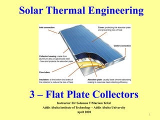
  • 4. Mail Components of a Typical Flat Plate Collector Flat plate collector is typically a metal box with  a glass or plastic cover (called glazing) on top  and a dark-colored absorber plate on the bottom  the sides and bottom of the collector are usually insulated to minimize heat loss  Absorber plate: It is usually made of copper, steel or plastic. The surface is covered with a flat black material of high absorptance. If copper or steel is used it is possible to apply a selective coating that maximizes the absorptance of solar energy and minimizes the radiation emitted by plate.  Flow passages: The flow passages conduct the working fluid through the collector. If the working fluid is a liquid , the flow passage is usually a tube that is attached to or is a part of absorber plate. If the working fluid is air, the flow passage should be below the absorber plate to minimize heat losses. 4
  • 5.  Cover plate:  To reduce convective and radiative heat losses from the absorber, one or two transparent covers are generally placed above the absorber plate.  They usually be made from glass or plastic.  Insulation  Insulation is some material such as fiberglass and it is placed at the back and sides of the collector to reduce heat losses.  Enclosure  Enclosure is used holds the components together, protect them from weather, facilitates installation of the collector on a roof or appropriate frame.
  • 6. Absorber plate & Flow passages  Copper,which has high conductivity and is corrosion-resistant, is the material for absorber plates,  but since copper is expensive, steel is also widely used.  The surface of the absorber plate determines how much of the incident solar radiation is absorbed and how much is emitted at a given temperature.  Flat black paint which is widely used as a coating has an absorptance of about 95 percent for incident shortwave solar radiation. It is durable and easy to apply. Material Absorptance () Emittance () Break down temparature (°C) Comments Black silicon paint 0.86-0.94 0.83-0.89 350 Slicone binder Black silicon paint 0.9 0.5 Stable at high temperature Black copper over copper 0.85-0.9 0.08-0.12 450 Patinates with moisture Black chorome over nickel 0.92-0.94 0.07-0.12 450 Stable at high temperatures
  • 7. Cover plates  A cover plate for a collector should have a high transmittance for solar radiation and should not detoriate with time.  The material most commonly used is glass. A 0.32-cm thick sheet of window glass ( iron content, 0.12 percent ) transmits 85 percent of solar energy at normal incidence.  And all glasses are opaque to long-wavelength radiation emitted by the absorber  Some plastic materials can be used for collector glazing.  They are cheaper and lighter than glass and,  However, they are not as durable as glass and they often degrade with exposure to ultraviolet radiation or high temperatures. Test Polyvinly floride Polyethylene terephthatalet or polyster Polycarbonate Fiberglass rein forced plastics Solar Transmission, % 92-94 85 82-89 77-90 Maximu operating temperature°C 110 100 120-135 95 Thermal Expansion Coefficient 43 27 68 32-40 Thickness, mm 0.1 0.025 3.2 1.0 Length of life, years In 5 years 95% retains 4 7-20
  • 8. Characteristics of insulation materials Material Density Kg/m3 Thermal conductivity at 95 °C (W/mK) Temperature limits °C Fiber glass with organic binder 11 0.059 175 “ 16 0.050 175 “ 24 0.045 175 “ 48 0.043 175
  • 9. Proper Orientatıon -Angle of Solar Collector Flat plate collectorts are divided in three main groups according to how they are oriented:  Flat-plate collectors facing south at fixed tilt  One-axis tracking flat-plate collectors with axis oriented north-south  Two-axis tracking flat-plate collectors
  • 10. Flat-plate Collectors Facing South at Fixed Tilt http://rredc.nrel.gov/solar/pubs/redbook/html/interp.html To optimize performance in the winter, the collector can be tilted 15 ° greater than the latitude; to optimize performance in the summer, the collector can be tilted 15° less than the latitude. .
  • 11. One-axis tracking flat-plate collectors with axis oriented north-south: These trackers pivot on their single axis to track the sun, facing east in the morning and west in the afternoon
  • 12. Two-axis tracking flat-plate collectors: Tracking the sun in both azimuth and elevation, these collectors keep the sun's rays normal to the collector
  • 13. 3.2 COLLECTOR PERFORMANCE John A. Duffie and William A. Beckman Basic Energy Balance Equation  In steady state, the performance of a solar collector is described by an energy balance that indicates the distribution of incident solar energy into:  Useful energy gain, Thermal losses, and Optical losses  Useful Energy Gain by the Collector ( Qu ) = = Energy Absorbedby the Collector – Heat Loss to Surroundings  In steady state the useful energy output of a collector of area is  The absorbed solar radiation – thermal Losses 13
  • 14. Where  S solar radiation absorbed by the solar collector  S = Incident solar radiation - Optical Losses • are the view factors from the collector to the sky and from the collector to the ground, respectively. The subscripts b,d, and g represent beam, diffuse, and ground , respectively • is transmittance and absorptance product • Rb is the ratio of beam radiation on the tilted surface to that on a horizantal surface at any time  UL (Tpm - Ta) is the thermal energy lost from the collector plate to the surroundings by conduction, convection, and infrared radiation  UL is the collector overall loss coefficient and it is equal to the sum of the top, bottom,and edge loss coefficients, UL=Utop+Ubottom+Uedge,W/m²K  Tpm, Ta and are mean absorber plate and ambient temperatures  Ac is collector area 14
  • 15.  The problem with eq (1) is that the mean absorber plate temperature is difficult to calculate or measure since it is a function of  the collector design, the incident solar radiation, and the entering fluid conditions. 15
  • 16. Temperature distribution between tubes and the collector efficiency factor  The function F is the standard fin efficiency for straight fins with rectangular profile and is plotted in next Figure 16
  • 17. 17
  • 18.  We now wish to eliminate Tb from the equations and obtain an expression for the useful gain in terms of known dimensions, physical parameters, and the local fluid temperature.  The collector efficiency factor is essentially a constant for any collector design and fluid flow rate. 18
  • 19. 19
  • 20.  Hence, an equation is formulated to replace eq (1) so that the useful energy gain can be expressed in terms of the inlet fluid temperature and a parameter called the collector heat removal factor (FR) which can be evaluated analytically from basic principles or experimentally measured data  This parameter relates the actual useful energy gain of a collector to the useful gain if the whole collector surface were at the fluid inlet temperature.  This equation is as follow Qu = AcFRS – AcFRUL(Ti – Ta ) or  This equation is an extremely useful equation and applies to essentialy all flat-plate collectors. 20
  • 21.  Equation (2) can be rewritten as Where  Collector heat Removal Factor (FR)  m = Fluid mass flow rate, kg/s  Cp = Fluid specific heat, J/kg°C  The quantitiy FR is equavialent to the effectiveness of a conventional heat exchange, which is defined as the ratio of the actual heat transfer to the maximum possible heat transfer. The maximum possible useful energy gain (heat transfer) in a solar collector occurs when the all whole collector is at the inlet fluid temperature; heat losses to the surroudings are then at a minimum.  is a transmittance-absorptance product that is weighted according to the proportions of beam, diffuse, and ground reflected radiation on the collector 21
  • 22.  The basic method of measuring collector performance is to expose the operating collector to solar radiation and measure the fluid inlet and outlet temperatures and the fluid flow rate.The useful gain is  Where;  m = Fluid mass flow rate, kg/s  Cp = Fluid specific heat, J/kg°C 22
  • 23.  What information is given in the diagram above  It is a diagram of typical flat plate collector  92 % of the total sunshine reaches to the copper absorber.  8% of the total sunshine is reflected from glass.  5% of the sunshine is emitted from the panel  12% is lost through convection and conduction 23
  • 24. Collector Effıcıency  the collection efficiency is the ratio of the useful gain over some specified time period to the incident solar energy over the same time period:  The instantaneous efficiency 24
  • 25. 3.3 TEMPERATURE DISTRIBUTIONS IN FLAT- PLATE COLLECTORS John A. Duffie and William A. Beckman 25  Figure (a) shows a region between two tubes. Some of the solar energy absorbed by the plate must be conducted along the plate to the region of the tubes. Thus the temperature midway between the tubes will be higher than the temperature in the vicinity of the tubes. The temperature above the tubes will be nearly uniform because of the presence of the tube and weld metal. The energy transferred to the fluid will heat the fluid, causing a temperature gradient to exist in the direction of flow.
  • 26.  Since in any region of the collector the general temperature level is governed by the local temperature level of the fluid, a situation as shown in Figure (b) is expected.  At any location y, the general temperature distribution in the x direction is as shown in Figure (c), and  At any location x, the temperature distribution in the y direction is as shown in Figure (d). 26
  • 27. To model the situation shown in the figure, a number of simplifying assumptions can be made to lay the foundations without obscuring the basic physical situation. These are:  Performance is steady state.  Construction is of sheet and parallel tube type  The headers cover a small area of collector and can be neglected  The headers provide uniform flow to tubes  There is no absorption of solar energy by a cover insofar as it affects losses from the collector.  Heat flow through a cover is one dimensional  There is a negligible temperature drop through a cover  The covers are opaque to infrared radiation  There is one-dimensional heat flow through back insulation 27  The sky can be considered as a blackbody for long-wavelength radiation at an equivalent sky temperature  Temperature gradients around tubes can be neglected  The temperature gradients in the direction of flow and between the tubes can be treated independently  Properties are independent of temperature  Loss through front and back are to the same ambient temperature  Dust and dirt on the collector are negligible  Shading of the collector absorber plate is negligible.
  • 28. 3.4 COLLECTOR OVERALL HEAT LOSS COEFFICIENT John A. Duffie and William A. Beckman  The absorbed energy S is distributed to  To thermal losses through the top, bottom and edge  To useful energy gain  The energy loss through the top is the result of convection and radiation between parallel plates.  The steady-state energy transfer between the plate at Tp and the first cover at Tc1 is the same as between any other two adjacent covers and is also equal to the energy lost to the surroundings from the top cover. 28
  • 29.  Thermal network for a two-cover flat-plate collector:  (a) in terms of conduction, convection, and radiation resistances;  (b) in terms of resistances between plates.  (c) Equivalent thermal network for flat-plate solar collector. 29
  • 30. Where  h c,p-c1 is the convection heat transfer coefficient between the absorber plate and the frist glass coverer  If the definition of the radiation heat transfer coefficient is to be used, the heat loss equation becomes 30 3.4.1 Top Loss Heat Loss from the absorber Plate to the first glass cover
  • 31. Heat Loss from the first glass cover to the Second Glass Cover  A similar expression can be written for R2, the resistance between the two glass covers. 31
  • 32. Heat Loss from the Second Glass Cover to the Surrounding  The heat loss from flat plates exposed to outside winds is important in the study of solar collectors  Therefore, for two-cover system, the top loss coefficient from the collector plate to the ambient Ut is 32
  • 33.  In solving the top loss coefficient using Equations 7 to15 is necessarily an iterative process.  First a guess is made of the unknown cover temperatures, from which the convective and radiative heat transfer coefficients between parallel surfaces are calculated. With these estimates, Equation 15 can be solved for the top loss coefficient. The top heat loss is the top loss coefficient times the overall temperature difference, and since the energy exchange between plates must be equal to the overall heat loss, a new set of cover temperatures can be calculated. Beginning at the absorber plate, a new temperature is calculated for the first cover. 33
  • 34.  This new first cover temperature is used to find the next cover temperature, and so on. For any two adjacent covers or plate, the new temperature of plate (cover) j can be expressed in terms of the temperature of plate (cover) i as  The process is repeated until the cover temperatures do not change significantly between successive iterations. The following example illustrates the process. 34
  • 35. Example (Example 6.4.1Text book)  Calculate the to loss coefficient for an absorber with a single glass cover having the following specifications: Plate-to-cover spacing 25 mm Plate emittance 0.95 Ambient air and sky temperature 10oC Wind heat transfer coefficient 10W/m2oC Mean plate temperature (Tp) 100oC Collector tilt 45o Glass emittance 0.88 35
  • 36. 36
  • 37.  The procedure is to estimate the cover temperature, from which hc,p-c, hr,p-c and hr,c-a are calculated. With these heat transfer coefficients and hw, the top loss coefficient is calculated. These results are then used to calculate Tc from the preceding equation,. If Tc is close to the initial guess, no further calculations are necessary. Otherwise, the newly calculated Tc is used and the process is repeated. Let first assume Tc =35oC. With this the two radiation coefficient are hr,p-c = 7.60 W/m2, hr,c-a = 5.16W/m2 The mean temperature b/n the plate and the cover is (100+35)/2 = 67.5oC. At this temperature the air properties are 37
  • 38. 38
  • 39. 39
  • 40. 40
  • 41.  The calculation of the top loss coefficient is a tedious process.  To simplify calculations of collector performance, Figures (a–f) have been prepared. These figures give the top loss coefficient for one, two, and three glass covers. 41
  • 42.  Even though the top loss coefficients of figures a- f are for a plate spacing of 25 mm, they can be used for other plate spacing with little error as long as the spacing is greater than about 15 mm. 42
  • 43. 43
  • 44. 44
  • 45. Typical Variation of Top Loss Coefficient with Plate Spacing using a slope ß of 45o  N is number of glass plates 45
  • 46. Dependence of top loss coefficient on slope. 46
  • 47.  An empirical equation for Ut that is useful for both hand and computer calculations was developed by Klein (1979) following the basic procedure of Hottel and Woertz (1942) and Klein (1975). This relationship fits the graphs for Ut for mean plate temperatures b/n ambient and 200oC to within ±0.3 W/m2 oC. 47
  • 48. 48
  • 49. 49
  • 50. 3.4.1 Bottom Loss  The energy loss through the bottom of the collector is represented by two series resistors,  R4 (represents the resistance to heat flow) and R5 (Represents the convection and radiation resistance to the environment.  The magnitudes of R4 and R5 are such that it is usually possible to assume R5 is zero and all resistance to heat flow is due to the insulation. Thus, the back loss coefficient Ub is approximately  where k and L are the insulation thermal conductivity and thickness, respectively. 50
  • 51. 3.4.1 Edge Loss  Tabor (1958) recommends edge insulation of about the same thickness as bottom insulation.  The edge losses are then estimated by assuming one- dimensional sideways heat flow around the perimeter of the collector system.  The losses through the edge should be referenced to the collector area. If the edge loss coefficient–area product is (UA)edge, then the edge loss coefficient, based on the collector area Ac ,is 51
  • 52.  If it is assumed that all losses occur to a common sink temperature Ta, the collector overall loss coefficient UL is the sum of the top, bottom, and edge loss coefficients 52
  • 53. 53
  • 54.  The edge loss for this 30-m2 collector array is a little over 1% of the total losses. Note, however, that if this collector were 1 × 2 m, the edge losses would increase to over 5%.  Thus, edge losses for well-constructed large collector arrays are usually negligible, but for small arrays or individual modules the edge losses may be significant. Also note that only the exterior perimeter was used to estimate edge losses.  If the individual collectors are not packed tightly together, significant heat loss may occur from the edge of each module. 54
  • 55.  The preceding discussion of top loss coefficients, are based on covers like glass that are opaque to long-wavelength radiation.  If a plastic material must be modified to account for some infrared radiation passing directly through the cover. For a single cover that is partially transparent to infrared radiation, the net radiant energy transfer directly between the collector plate and the sky is used to replace one or more covers, the equation for Ut must be modified to account for some infrared radiation passing directly through the cover. For a single cover that is partially transparent to infrared radiation, the net radiant energy transfer directly between the collector plate and the sky is  where τc and ρc are the transmittance and reflectance of the cover for radiation from Tp and from Ts (assuming that the transmittance is independent of source temperature or that Tp and Ts are nearly the same) and εp and ρp are the emittance and reflectance of the plate for long-wave radiation. 55
  • 56.  The top loss coefficient then becomes  The evaluation of the radiation heat transfer coefficients in Equation (22) must take into account that the cover is partially transparent.  The net radiation between the opaque plate and the partially transparent cover is given by  The radiation heat transfer coefficient between the plate and cover is just the net heat transfer divided by the temperature difference: 56
  • 57. 3.5 EFFECTS OF DUST AND SHADING John A. Duffie and William A. Beckman  The effects of dust and shading are difficult to generalize.  Data reported by Dietz (1963) show that at the angles of incidence of interest (0 to 50o) the maximum reduction of transmittance of covers due to dirt was 2.7%. From long-term experiments on collectors in the Boston area, Hottel and Woertz (1942) found that collector performance decreased approximately 1% due to dirty glass.  In a rainless 30-day experiment in India, Garg (1974) found that dust reduced the transmittance by an average of 8% for glass tilted at 45o.  To account for dust in temperate climates, it is suggested that radiation absorbed by the plate be reduced by 1%; in dry and dusty climates, absorbed radiation can be reduced by 2%. 57
  • 58.  Shading effects can also be significant.  Whenever the angle of incidence is off normal, some of the collector structure will intercept solar radiation.  Some of this radiation will be reflected to the absorbing plate if the sidewalls are of a high-reflectance material. Hottel and Woertz (1942), based on experiments with two- cover collectors, recommend that the radiation absorbed by the plate be reduced by 3% to account for shading effects if the net (unobstructed) glass area is used in all calculations. The net glass area accounts for the blockage by the supports for the glass. Most modern collectors use one cover, and module areas are larger, both of which reduce shading effects.  A reduction of S of 1% may be a more appropriate correction for these collectors. 58
  • 59.  Where KL is extinction length, K is proportionality constant (extinction coefficient) which is assumed to be a constant in the solar spectrum. K varies from approximately 4 m−1 for ‘‘water white’’ glass to approximately 32 m−1 for high iron oxide content glass. 59
  • 60. 3.6 SOLAR LIQUID HEATER  The first three have parallel tubes (risers) thermally fastened to a plate and connected at the top and bottom by headers to admit and remove the liquid.  The design shown in (b) is the same as (a), except that the tubes are mounted on top of the plate rather than under it.  (c) has the tubes centered in the plane of the plate forming an integral part of the plate structure.  (d), (e), and (f), long, narrow, flat absorbers are mounted inside evacuated glass tubes.  (g) the serpentine tube arrangement
  • 61. 61
  • 62. 62
  • 63. 63
  • 64.  For a single bend, Zhang and Lavan show that the solution for FR is given by the equation below in terms of three dimensionless parameters F1, F2, and F3 (the parameters F4, F5, and F6 are functions of F2 only) 64
  • 65.  Zhang and Lavan (1985) point out that Equation (25) is valid for any number of bends if the group mcp / F1ULAcis greater than about 1.0.  For smaller values of this group, their paper should be consulted. 65
  • 66. 66
  • 67. 67
  • 68. 68
  • 69.  The most common liquid solar heater is uncovered and used for low-temperature applications such as swimming pool heating.  These collectors are typically made from plastics such as stabilized polyolefin.  The parallel-flow channels either are in direct contact with one another or are connected by very short fins.  The short fins are necessary due to the low thermal conductivity of the plastic material.  The same basic equations apply for these collectors, but the lack of a cover means that estimating the collector loss coefficient is very uncertain. 69
  • 70. 3.7 SOLAR AIR HEATERS 70
  • 71. 71
  • 72.  At some location along the flow direction the absorbed solar energy heats up the plate to a temperature Tp.  Energy is transferred from the plate to the ambient air at Ta through the back loss coefficient Ub , to the fluid at Tf through the convection heat transfer coefficient h2, and to the bottom of the cover glass through the linearized radiation heat transfer coefficient h1.  Energy is transferred to the cover glass from the fluid through the heat transfer coefficient hr.  Energy is lost to the ambient air through the combined convection and radiation coefficient Ut.  Note that Ut can account for multiple covers.  Energy balances on the cover, the plate, and the fluid yield the following equations: 72
  • 73.  These three equations are solved so that the useful gain is expressed as a function of Ut, h1, h2, hr, Tf, and Ta.  In other words, Tp and Tc must be eliminated. The algebra is somewhat tedious and only a few of the intermediate steps are given. Solving the first two equations for Tp – Tf and Tc – Tf, 73
  • 74.  Substituting these into the equation for qu and rearranging, we obtain 74
  • 75.  Note that UL for this collector is not just the top loss coefficient in the absence of back losses but also accounts for heat transfer between the absorbing surface and the bottom of the cover.  Whenever the heat removal fluid is in contact with a transparent cover, UL will be modified in a similar fashion.  The equations for type (b) air heaters are derived in a similar manner, but the working fluid does not contact the cover system.  For simplicity, back losses are assumed to occur from the absorber plate temperature. The following example shows calculation of the performance of a type (b) air heater. 75
  • 76. 76
  • 77. 77
  • 78. 78
  • 79. 79
  • 80. 80
  • 81. 81