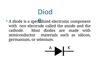
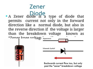
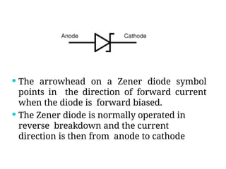
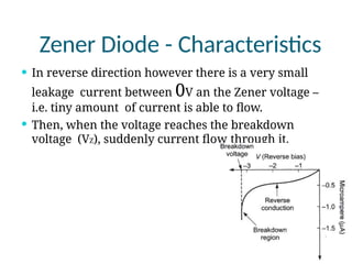
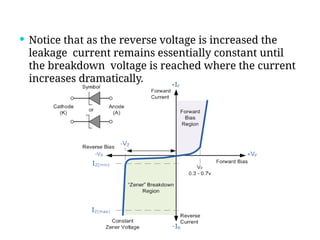
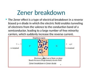
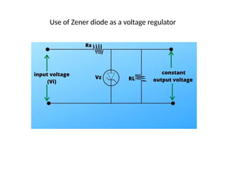
Topic:
Diode
Diod
e
 A diode is a specialized electronic component
with two electrode called the anode and the
cathode. Most diodes are made with
semiconductor materials such as silicon,
germanium, or selenium.
Zener Diode -
History
 Clarence Melvin Zener (December 1, 1905 – July 2,
1993) was the American physicist who first
described the property concerning the breakdown
of electrical insulators. These findings were later
exploited by Bell Labs in the development of the
Zener diode, which was duly named after him
Zener
Diode
 A Zener diode is a type of diode that
permits current not only in the forward
direction like a normal diode, but also in
the reverse direction if the voltage is larger
than the breakdown voltage known as
“Zener knee voltage” or “Zener voltage”
 The arrowhead on a Zener diode symbol
points in the direction of forward current
when the diode is forward biased.
 The Zener diode is normally operated in
reverse breakdown and the current
direction is then from anode to cathode
Zener Diode -
Circuit
 The most basic Zener diode circuit consist of a
single Zener diode and a resister.
 The Zener diode provides the reference voltage,
but a series resistor must be in place to limit the
current into the diode otherwise a large amount
of current would
flow through it and it could be destroyed.
 The value of resistor
calculated to give required
value of current for supply
voltage used.
Zener Diode – Forward
bias
 When a Zener diode is forward biased, it
operates as a normal diode.
 In forward biased P side connected to +ve and N
side connected to –ve terminal of battery. In this
case the electrons and holes are swept across the
junction an large current flow through it.
Zener Diode – Reverse
biased
 In case of reverse biased current practically
zero and at certain voltage which called
Zener voltage the current increases
sharply.
 Each Zener diode has breakdown rating
which specifies the max voltage that can
be dropped across it.
Zener Diode -
Characteristics
 The figure shows, the forward
characteristics is same as that of ordinary
forward biased junction diode.
Zener Diode - Characteristics
 In reverse direction however there is a very small
leakage current between 0V an the Zener voltage –
i.e. tiny amount of current is able to flow.
 Then, when the voltage reaches the breakdown
voltage (VZ), suddenly current flow through it.
 Notice that as the reverse voltage is increased the
leakage current remains essentially constant until
the breakdown voltage is reached where the current
increases dramatically.
Zener breakdown
 The Zener effect is a type of electrical breakdown in a reverse
biased p-n diode in which the electric field enables tunneling
of electrons from the valence to the conduction band of a
semiconductor, leading to a large number of free minority
carriers, which suddenly increase the reverse current.
Basic Parameters of a Zener Diode
 The Zener Voltage (Vz) must be specified. The most
common range of zener voltage is 3.3 to 75 volts,
however voltage out of this range are available.
 A tolerance of the specified voltage must be stated.
While the most popular tolerance are 5% and
10%,more precision tolerance as low as 0.05% are
available. A test current (Iz) must be specified with
the voltage and tolerance.
 The power handling capability must be specified for
the zener diode. Popular power ranges are: ¼, ½, 1,
5, 10 and 50 watts.
The most common application of Zener Diode
1. Zener Regulator
2. Zener Comparator
3. Zener Limiters
4. Zener in Power
Supplies
Use of Zener diode as a voltage regulator

Zener Diode Introduction and working .pptx

  • 1.
  • 2.
    Diod e  A diodeis a specialized electronic component with two electrode called the anode and the cathode. Most diodes are made with semiconductor materials such as silicon, germanium, or selenium.
  • 3.
    Zener Diode - History Clarence Melvin Zener (December 1, 1905 – July 2, 1993) was the American physicist who first described the property concerning the breakdown of electrical insulators. These findings were later exploited by Bell Labs in the development of the Zener diode, which was duly named after him
  • 4.
    Zener Diode  A Zenerdiode is a type of diode that permits current not only in the forward direction like a normal diode, but also in the reverse direction if the voltage is larger than the breakdown voltage known as “Zener knee voltage” or “Zener voltage”
  • 5.
     The arrowheadon a Zener diode symbol points in the direction of forward current when the diode is forward biased.  The Zener diode is normally operated in reverse breakdown and the current direction is then from anode to cathode
  • 6.
    Zener Diode - Circuit The most basic Zener diode circuit consist of a single Zener diode and a resister.  The Zener diode provides the reference voltage, but a series resistor must be in place to limit the current into the diode otherwise a large amount of current would flow through it and it could be destroyed.  The value of resistor calculated to give required value of current for supply voltage used.
  • 7.
    Zener Diode –Forward bias  When a Zener diode is forward biased, it operates as a normal diode.  In forward biased P side connected to +ve and N side connected to –ve terminal of battery. In this case the electrons and holes are swept across the junction an large current flow through it.
  • 8.
    Zener Diode –Reverse biased  In case of reverse biased current practically zero and at certain voltage which called Zener voltage the current increases sharply.  Each Zener diode has breakdown rating which specifies the max voltage that can be dropped across it.
  • 9.
    Zener Diode - Characteristics The figure shows, the forward characteristics is same as that of ordinary forward biased junction diode.
  • 10.
    Zener Diode -Characteristics  In reverse direction however there is a very small leakage current between 0V an the Zener voltage – i.e. tiny amount of current is able to flow.  Then, when the voltage reaches the breakdown voltage (VZ), suddenly current flow through it.
  • 11.
     Notice thatas the reverse voltage is increased the leakage current remains essentially constant until the breakdown voltage is reached where the current increases dramatically.
  • 12.
    Zener breakdown  TheZener effect is a type of electrical breakdown in a reverse biased p-n diode in which the electric field enables tunneling of electrons from the valence to the conduction band of a semiconductor, leading to a large number of free minority carriers, which suddenly increase the reverse current.
  • 13.
    Basic Parameters ofa Zener Diode  The Zener Voltage (Vz) must be specified. The most common range of zener voltage is 3.3 to 75 volts, however voltage out of this range are available.  A tolerance of the specified voltage must be stated. While the most popular tolerance are 5% and 10%,more precision tolerance as low as 0.05% are available. A test current (Iz) must be specified with the voltage and tolerance.  The power handling capability must be specified for the zener diode. Popular power ranges are: ¼, ½, 1, 5, 10 and 50 watts.
  • 14.
    The most commonapplication of Zener Diode 1. Zener Regulator 2. Zener Comparator 3. Zener Limiters 4. Zener in Power Supplies
  • 15.
    Use of Zenerdiode as a voltage regulator