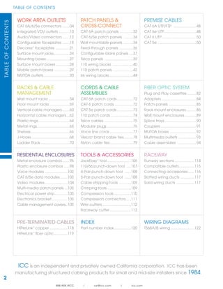
This document is a catalog for structured cabling products including:
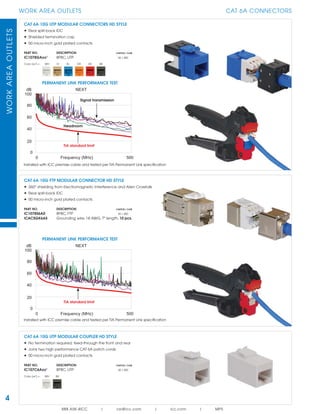
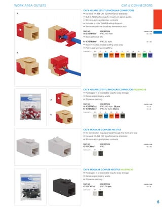
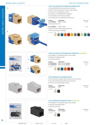
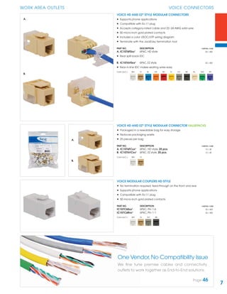
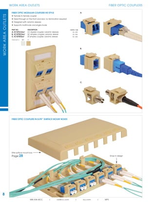
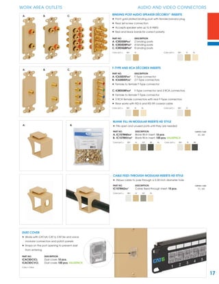
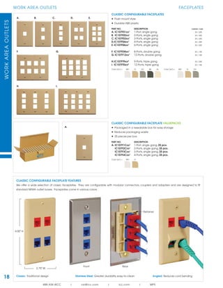
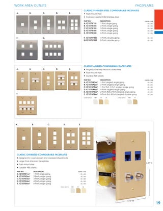
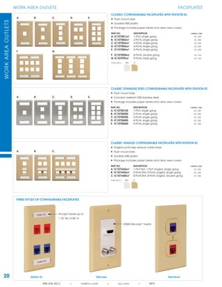
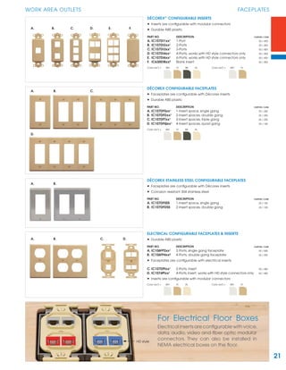
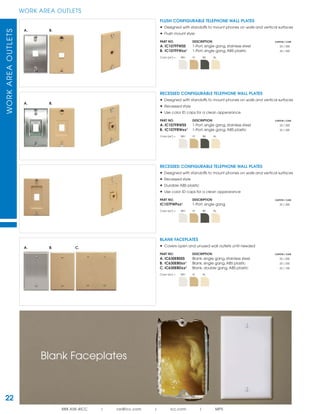
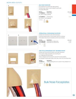
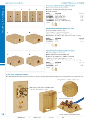
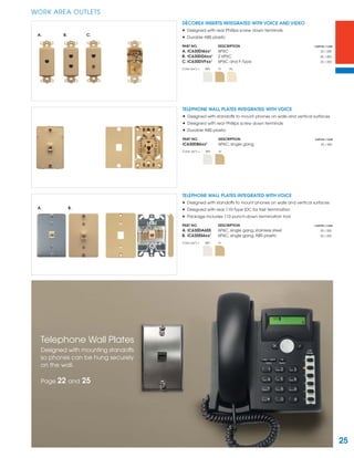
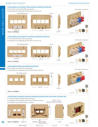
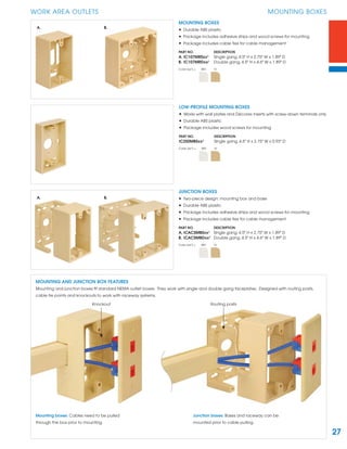
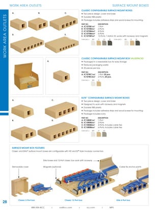
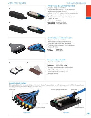
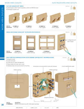
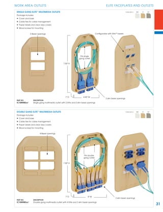
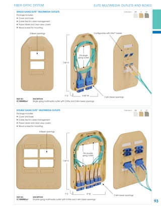
1. Work area outlets such as connectors, faceplates, jacks, and boxes for copper and fiber optic cabling.
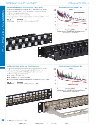
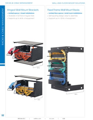
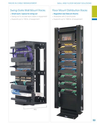
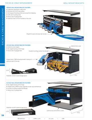
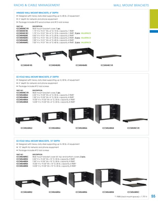
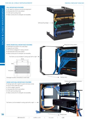
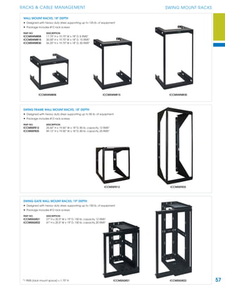
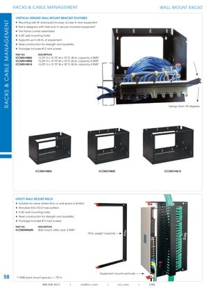
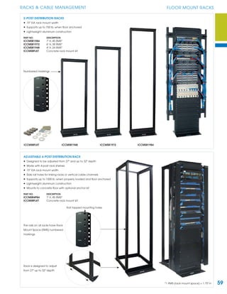
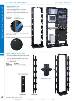
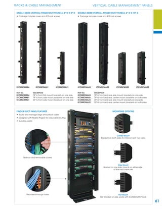
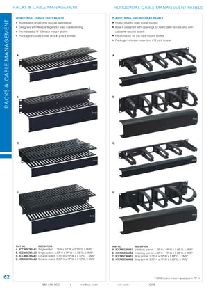
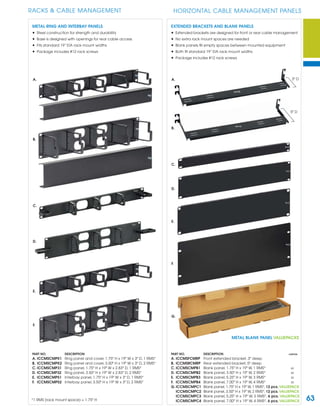
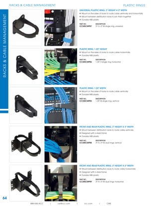
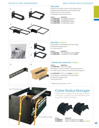
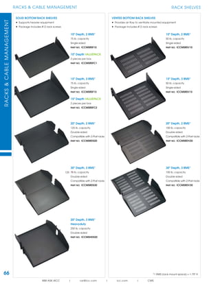
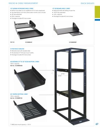
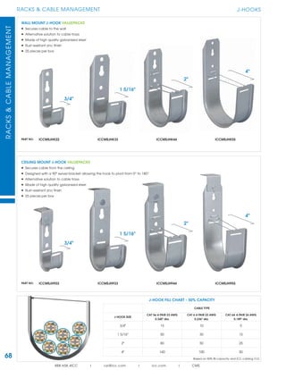
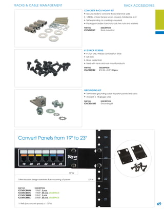
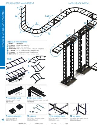
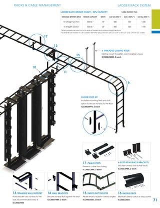
2. Rack and cable management products like racks, cable managers, shelves, and accessories.
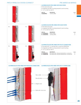
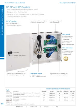
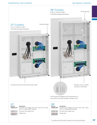
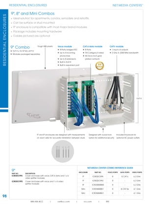
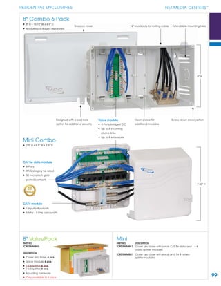
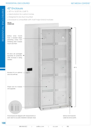
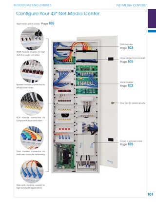
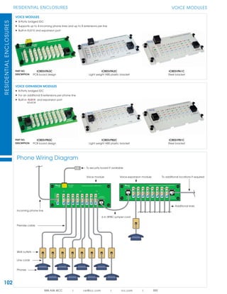
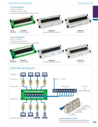
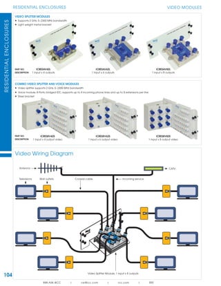
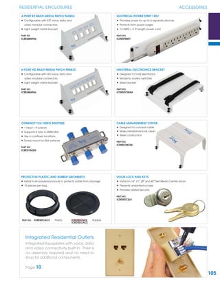
3. Residential enclosures and patch panels for small work areas.
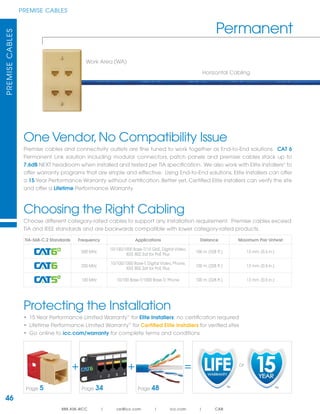
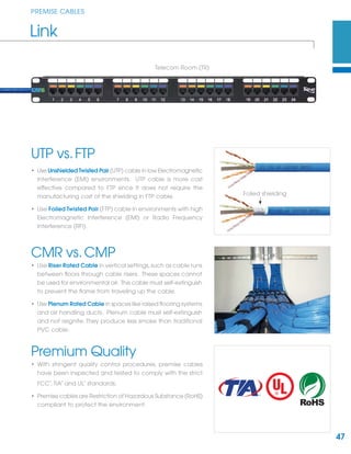
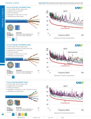
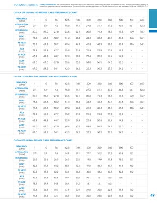
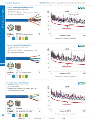
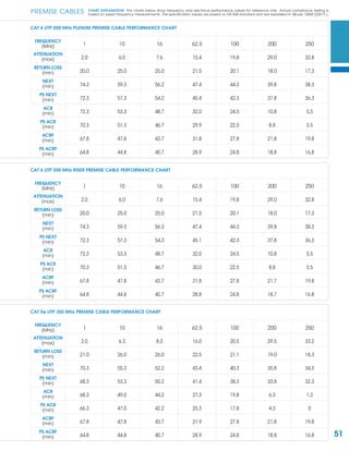
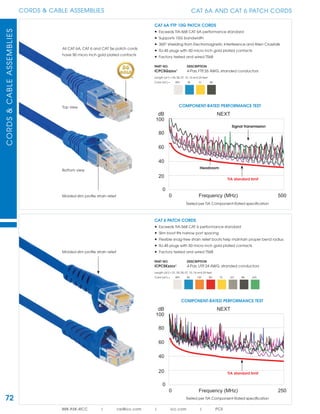
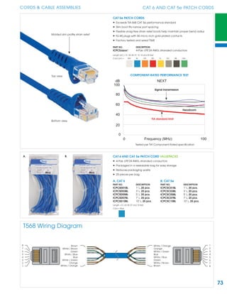
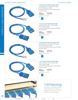
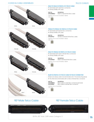
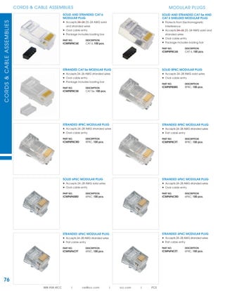
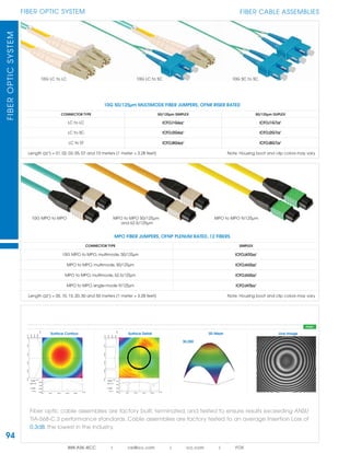
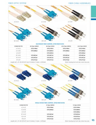
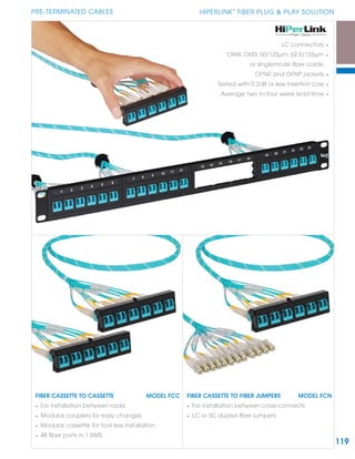
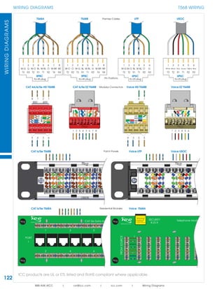
4. Premise cables, pre-terminated cables, patch cords, and fiber optic components.
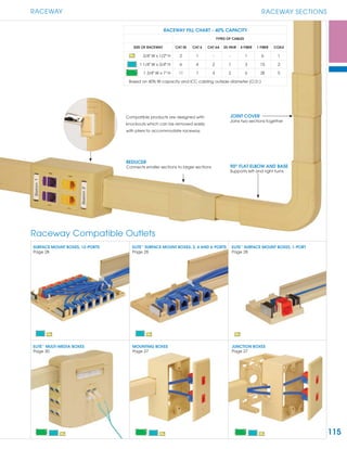
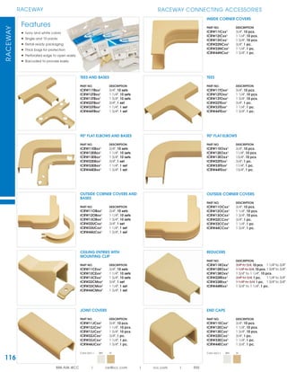
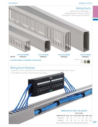
5. Raceway, wiring ducts, and accessories for cable routing.
It provides product descriptions, part numbers, and packaging information for a wide range of structured cabling infrastructure components.